


Introduction
Supported by the US National Science Foundation, a new 1751 m long ice core was recovered at the South Pole, extending >54 000 years into the past (Winski and others, Reference Winksi2019). Scientists from 13 different US institutions are using the ice core to obtain measurements of the chemistry and physical properties of the ice core and the entrapped air, which provides records of the climate history of a unique area of East Antarctica. The South Pole ice core (SPICEcore) is the highest-resolution interior East Antarctic ice core that extends into the last glacial period and is the first record longer than 3000 years collected south of 82° latitude (Fig. 1). SPICEcore provides a record of climate history from a distinct area of the East Antarctic plateau that is influenced both by conditions of the high East Antarctic plateau and by weather systems that cross the West Antarctic ice sheet from the Atlantic Weddell Sea (Filchner–Ronne Ice Shelf) and Pacific Ross Seas (Ross Ice Shelf). Indeed, the South Pole site is unique in that average annual surface temperature (surface air temperature −49°C, firn temperature −51°C) is more typical of East Antarctic sites, whereas the average accumulation rate of ~8 cm w.e. a−1 is more typical of West Antarctic sites (Hogan and Gow, Reference Hogan and Gow1997; Severinghaus and others, Reference Severinghaus, Grachev and Battle2001; Lazarra and others, Reference Lazzara, Keller, Markle and Gallagher2012; Casey and others, Reference Casey2014; Fegyveresi and others, Reference Fegyveresi, Fudge, Winski, Ferris and Alley2019). Because of the very cold temperatures, low impurity levels and the relatively high accumulation rate at the South Pole, novel measurements of rare atmospheric gases (Nicewonger and others, Reference Nicewonger, Aydin, Prather and Saltzman2018, Reference Nicewonger, Aydin, Prather and Saltzman2020) at high-resolution are possible within the SPICEcore.
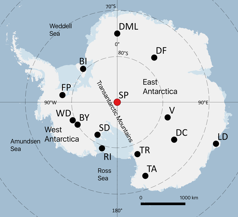
Fig. 1. Map of Antarctica with deep ice core locations labeled: South Pole (SP), Berkner Island (BI), Byrd (BY), EPICA Dome C (DC), Dome Fuji (DF), Dronning Maud Land (DML), Fletcher Promontory (FP), Law Dome (LD), Roosevelt Island (RI), Siple Dome (SD), Talos Dome (TA), Taylor Dome (TR), Vostok (V), WAIS Divide (WD). The SPICEcore is the highest-resolution interior East Antarctic ice core that extends into the last glacial period and is the first record longer than 3000 years collected south of 82° latitude.
SPICEcore was drilled during austral field seasons 2014/15 and 2015/16 using the new US Intermediate Depth Drill (IDD) (Johnson and others, Reference Johnson, Shturmakov, Kuhl, Mortensen and Gibson2014; Table 1). A third austral field season (2016/17) was utilized to allow the second season's ice from the ‘brittle ice zone’ to relax on-site before packing and shipment to the USA, although in hindsight the ice was not very brittle in nature. Very few measurements were performed on the ice core in the field. The primary goal of the on-site core handling was to remove as much of the ESTISOLTM 140 drill fluid from the core as possible, conduct precise initial length and depth logging, document any notable ice characteristics, cut the 2 m long drill runs of ice into 1 m long sections, and safely prepare the ice for transport back to the National Science Foundation Ice Core Facility (NSF-ICF) in Denver, Colorado, USA, for repeated length and depth logging and subsequent sample cutting. Details of the drilling operation are described in Johnson and others (Reference Johnson2020). Here, we discuss the methods used for handling and logging the drilled ice at the South Pole, the procedures used to retrograde the ice back to the NSF-ICF, and the methods used for processing and sampling the ice once on-site at the NSF-ICF.
Table 1. Summary of drilling and core handling activities at the South Pole
a Two people filled the role by each deploying for half of the season.
b Three core handlers deployed with one staying the entire season and two others splitting the season in half.
Drill site
The Amundsen–Scott South Pole Station (South Pole Station) is located on the polar plateau at an altitude of 2835 m (9300 ft). It is one of the three year-round occupied research stations operated by the US Antarctic Program in Antarctica. South Pole Station, which is 1374 km (850 nautical miles) south of McMurdo Station, is a major hub for science and logistics activities. The winter population is ~45, and the summer population averages 150.
The SPICEcore drill site was located in the station's ‘Dark Sector’, grid west of South Pole Station, at 89.99° S, 98.16° W. The ‘Dark Sector’ is a defined area at South Pole Station that is kept clear of sources of interference with electromagnetic signals that could hamper radio telescopes. The drill site was 2.7 km (1.7 miles) travel distance via a groomed snow road from South Pole Station. Details of the site selection process are described in Casey and others (Reference Casey2014). The South Pole has an estimated ice thickness of 2700 m (Casey and others, Reference Casey2014). We estimate the firn bubble close-off depth near the SPC14 site to be in the 120–123 m range based on previous firn studies at the South Pole (Battle and others, Reference Battle1996; Severinghaus and Battle, Reference Severinghaus and Battle2006). Modern ice velocities at the core site are 10 m a−1 along 40° W (IceCube Collaboration, 2013) and the deepest ice recovered at SPICEcore (1751 m is 54 302 ± 519 BP (years before 1950) (Winski and others, Reference Winksi2019)) likely originates ~150 km away at Titan Dome (Lilien and others, Reference Lilien2018; Fudge and others, Reference Fudge2020). SPICEcore was intentionally not drilled to bedrock due to the drill site location being away from an ice-flow divide and this increases the likelihood that deeper ice is stratigraphically disturbed. We note, however, that the ice is evidently undisturbed at greater depths than the 1500 m limit originally suggested by the interpretation of radar data (Casey and others, Reference Casey2014).
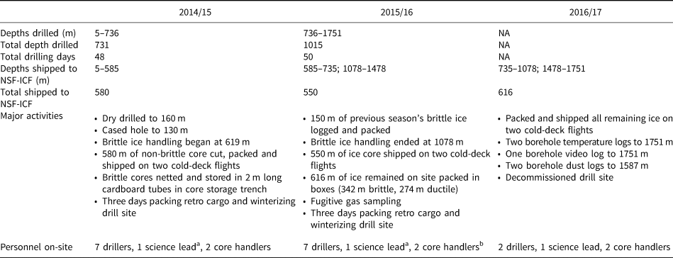
South Pole Station provided the logistical support required to establish and operate the SPICEcore field camp, including heavy-equipment, various camp structures, generators and occasional construction personnel. All project-specific cargo was transported to the South Pole Station via ski-equipped Hercules LC-130s. SPICEcore personnel resided at South Pole Station and commuted to the drill site. The drill site was operational from late November until the last week of January each year, and temperatures generally ranged from −38°C to −25°C during the season. The structures at the drill site consisted of a hut used for warming and mechanical repairs, a dedicated hut to hang and dry drill fluid-covered clothes, an outhouse, and the drill tent (Fig. 2).
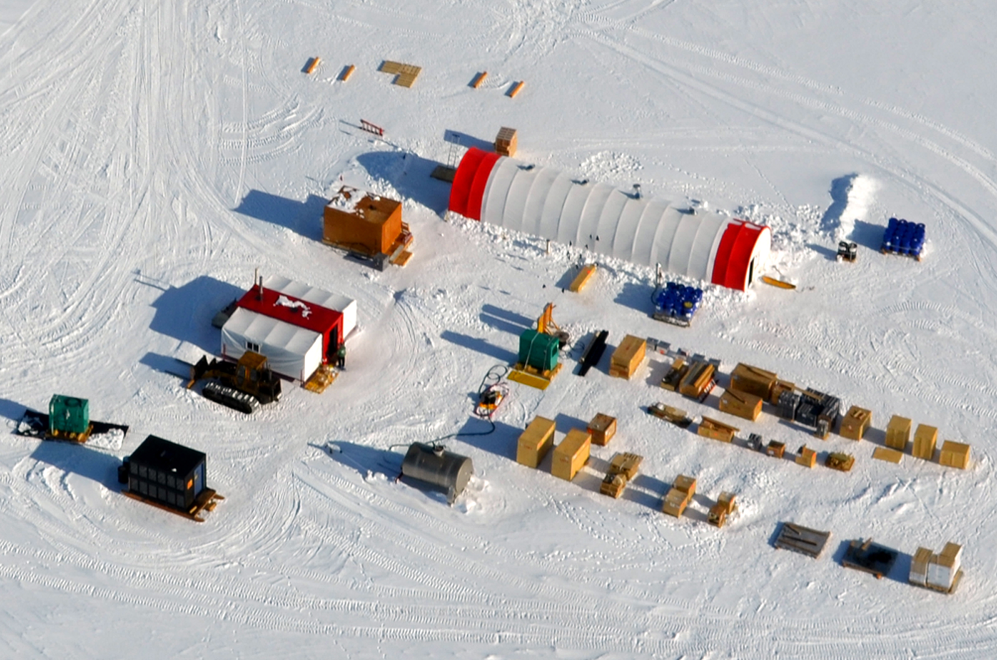
Fig. 2. Aerial view of the drill site showing the four main structures at the site: an outhouse (bottom left corner), a warming hut and mechanical repair space (rectangular white building with red center stripe), a dedicated hut to hang and dry drill fluid-covered clothes (orange rectangular building), and the drill tent (long white and red arch).
Core handling at South Pole
All drilling and core handling operations at the South Pole took place inside a 19.5 m (64 ft) × 4.9 m (16 ft) uninsulated drill tent. The floor of the drill tent was excavated to a depth of 1.4 m (4.6 ft) to reduce the height of the tent required and to help keep the interior of the tent cool (Johnson and others, Reference Johnson, Shturmakov, Kuhl, Mortensen and Gibson2014). There was no active refrigeration or cooling inside the drill tent, and the inside temperature generally ranged between −20 and −25°C. Radiative heating of the tent was mitigated by opening the doors on both ends of the tent; with the tent doors open, the interior temperature was quickly maintained to within a degree or two of the outside temperature. The drill tent was organized to accommodate a 24 hd−1, 6 d w−1 drilling operation producing 2 m of 98 mm diameter ice core per drill run. In line with the drill trench was a 6.4 m (21 ft) × 4.6 m (15 ft) underground core storage trench excavated to a depth of 3 m (10 ft). Figure 3 shows the layout of the drill tent and underground core storage trench.
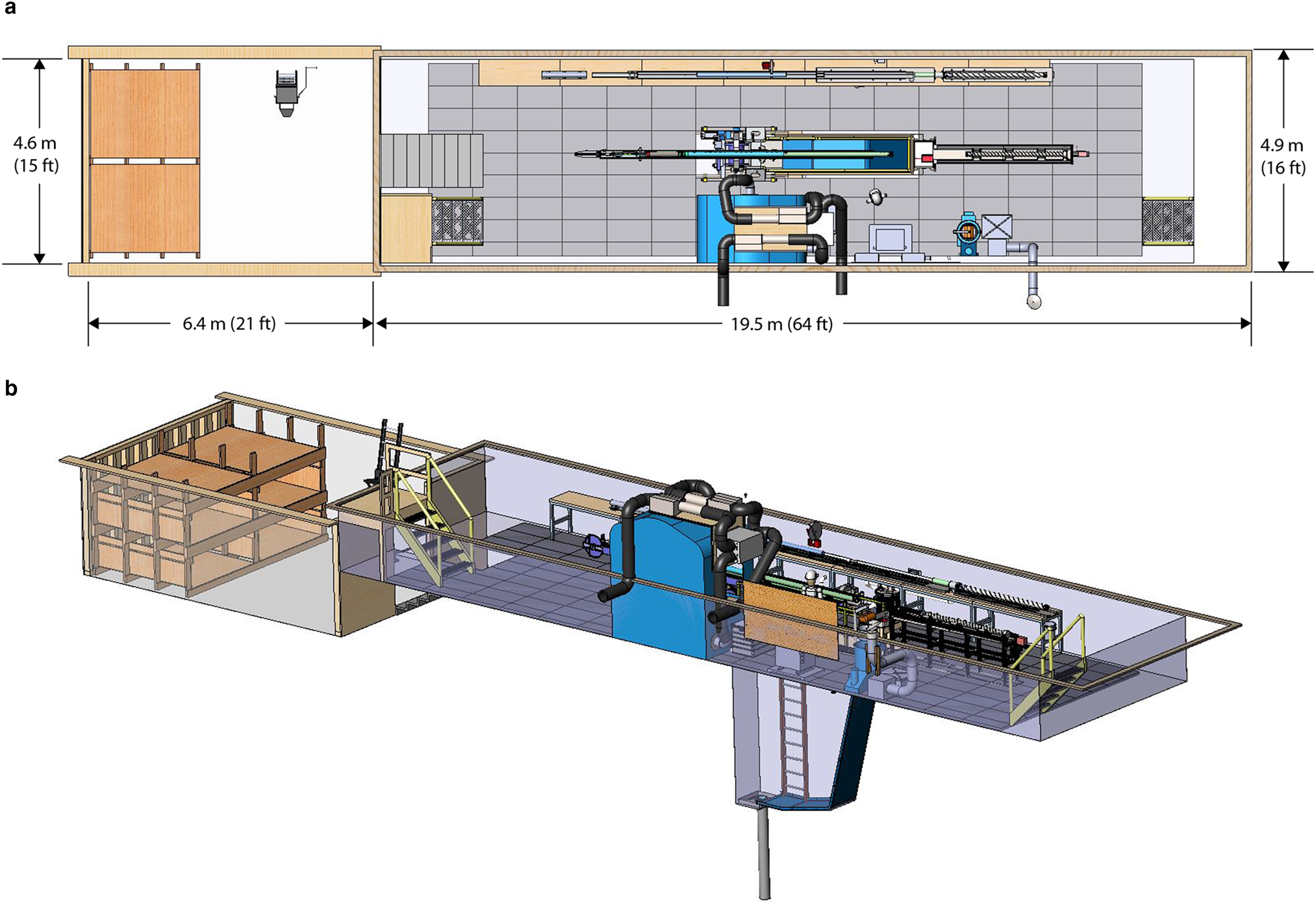
Fig. 3. Layout of the drill tent and the adjacent underground core storage trench in (a) plan view and (b) isometric projection. For details of the IDD, see Johnson and others (Reference Johnson, Shturmakov, Kuhl, Mortensen and Gibson2014). For details of the SPICEcore drilling operation, see Johnson and others (Reference Johnson2020).
The core handling line was designed by the US Ice Drilling Program (IDP; formerly Ice Drilling Design and Operations) at the University of Wisconsin–Madison. The primary goal of the on-site core handling was to remove as much of the ESTISOLTM 140 drill fluid from the core as possible, to make a precise initial length measurement as soon as the newly drilled core was pushed out of the barrel, to assign a depth to the ice, document any notable ice characteristics (e.g. ash layers, crusts, fractures and breaks), and to prepare the ice for shipment back to the USA. The core handling line was designed to handle drill runs of ice core up to 2 m in length and was designed to be simpler than the core handling system utilized for the WAIS Divide ice core project (Souney and others, Reference Souney2014). Figure 4 shows the layout of the core handling line. The core handling line, with an overall length of 12.8 m (42 ft), is built on seven benches that are rigidly connected together and leveled. Four 2 m (6.6 ft) long aluminum rail assemblies, which are adjustable so they can be accurately aligned, are mounted down the length of the table to maintain precise alignment of the core barrel and core trays. Located between the core push-out station (1) and the logging station (4) is the fluid evacuation device (FED) (Souney and others, Reference Souney2014) (2). This device, in conjunction with the vacuum system (3), is designed to remove drilling fluid from the surface of the ice core as it is pushed out of the core barrel. It also serves as an applicator for the elastic netting used to contain brittle ice (see Brittle ice procedure below). Immediately after the FED, the core tray slides away from the FED for loading netting onto the applicator tube, which then can be moved closer when the core is being pushed out the FED. Next in line is the cutting station, which features a dry-cut circular saw with a thin-kerf 355 mm (14 in) diameter tungsten carbide tipped blade for cutting the ice cores. The final station is for packing and includes a specially designed tray to assist with putting the core into polyethylene ‘lay-flat’ tubing and a fixture for holding the core tube while the core is inserted.
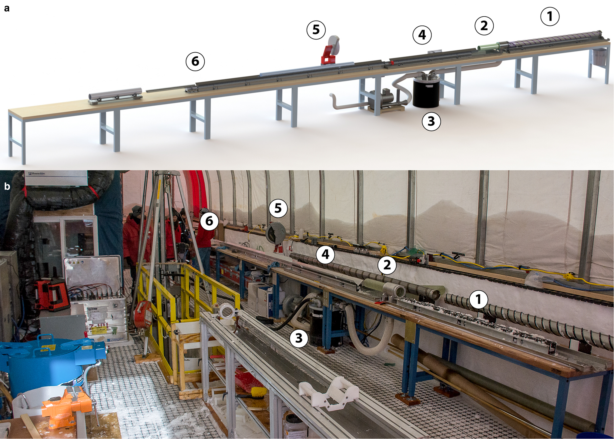
Fig. 4. (a) Layout of the core handling line inside the drill tent at the South Pole. (1) Core push-out station; (2) FED; (3) Vacuum pump, fluid containment drum and hand-vacuum; (4) Logging station; (5) Chop saw; (6) Packing. (b) Photograph of the core handling line at the South Pole.
General procedure
After each drill run, the IDD's tower and sonde were tilted horizontally to allow for the removal of the core barrel (Johnson and others, Reference Johnson2020). The core barrel, containing the run of ice core, was then transferred laterally by hand to the push-out table of the core handling line. The 2 m long run of the ice core was then pushed out of the core barrel and through the FED to remove the ESTISOLTM 140 drill fluid. The FED worked well removing some of the drill fluid, although it did not work as well as it did for the WAIS Divide ice core project due to the higher viscosity of the ESTISOLTM 140 drill fluid used for the SPICEcore project. Additional drill fluid was removed from the core using a hand-vacuum with a custom-fitted wand connected to the FED's pump (Fig. 5). Initially, the cores were also hand-wiped with an Isopar-soaked shop towel, followed by a wipe with a dry absorbent towel because Isopar-K was found to help remove ESTISOLTM 140 from ice. However, the hand-vacuuming was found to be simpler and more effective than using towels.
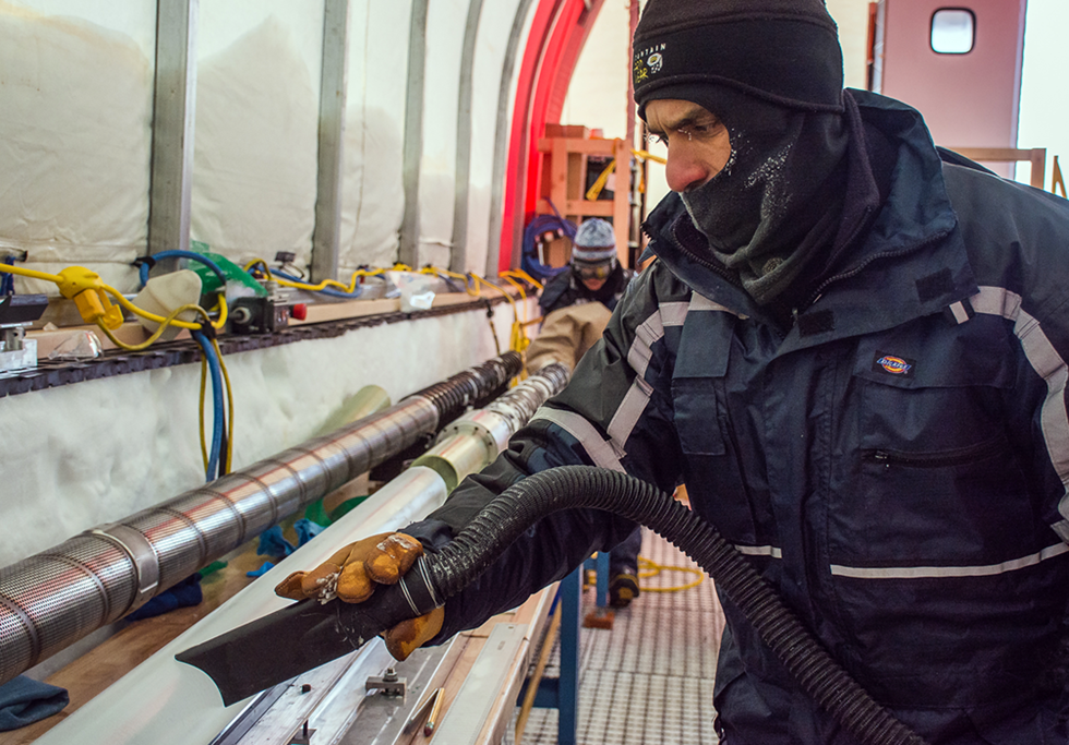
Fig. 5. Removing drill fluid from the core using the hand-vacuum.
After as much of the drill fluid was removed from the ice core as possible, the newly drilled core was logged following the procedures of Hvidberg and others (Reference Hvidberg, Steffensen, Clausen, Shoji and Kipfstuhl2002) to measure the length of the ice core and assign depths. Based on the Hvidberg and others (Reference Hvidberg, Steffensen, Clausen, Shoji and Kipfstuhl2002) procedure, index marks were drawn on every newly drilled 2 m section after matching the top of the new piece with the bottom of the ice from the previous run, and the distance between the consecutive index marks was documented. Depths of 1 m intervals were then marked on the ice core's surface. For each 1 m interval of the core, an arrow pointing in the vertically upward direction of the core was also marked on the ice core's surface. The ice core was inspected, and any fractures, spalls, breaks, cloudy layers or other visible features were documented. The logging information was recorded in a paper logbook and on core cards specific to each ~1 m long section of ice.
Once all of the logging was completed, and the 1 m depth marks assigned, the ice core was pushed down the core handling line to the cutting station. At the cutting station, the run of ice core was cut into 1 m long sections so that they fit into the standard-sized insulated shipping container (ISC) boxes used by the US ice-coring community to transport ice cores. There was a 2–3 mm kerf when the run of ice was cut into 1 m long sections. However, the Hvidberg and others (Reference Hvidberg, Steffensen, Clausen, Shoji and Kipfstuhl2002) logging procedure accounts for this lost kerf by virtue of the index marks penciled on the core. The 1 m long ice cores were then put into 0.152 mm (6 mil) thick polyethylene lay-flat tubing with the tube number, top depth, bottom depth and an arrow pointing to the vertically upward direction of the core written on the outside of the lay-flat. The respective core card for the 1 m long section of the core is also stapled to the end of the lay-flat. The ice core is then placed into an aluminum foil-coated cardboard core tube. Bubble wrap was placed at the ends of the core tube, when needed, to prevent the ice from sliding back-and-forth inside of the core tube. The core tube was then carried into the core storage trench and subsequently packed into an insulated core box, with each core box accommodating five core tubes. The void space around the core tubes was filled with snow, and a temperature data logger was included inside of each core box. Once closed, the core boxes were not opened again until safely inside the freezer facility at the NSF-ICF. In the deeper parts of the core, below the firn-ice transition, the packed core boxes weighed 60 kg (130 lb).
Brittle ice procedure
Based on the experience of previous intermediate and deep ice core drilling projects (Neff, Reference Neff2014; Souney and others, Reference Souney2014), it was anticipated that a brittle ice zone would be encountered at the South Pole at roughly equivalent depths as other East Antarctic ice cores. When the ice at the South Pole began exhibiting minor brittle behavior at 619 m depth, the core handling procedures were modified to help maintain the highest-quality ice. Immediately after every 2 m long run of ice exited the FED, it was extruded into elastic netting to ensure that if any breakage or cracking of the ice occurred during handling or transport, the core fragments would be contained and remain in place (Fig. 6). The netted ice was carefully hand-vacuumed to remove as much of the remaining drill fluid as possible. The elastic netting made it impossible to properly align and fit the runs of brittle ice tightly against one another during on-site processing. Therefore, precise depths for the brittle ice were not assigned in the field. Instead, the ends and total length of the runs of ice were measured to approximate millimeter precision, and shipping tags with the measured top depths and bottom depths were affixed to the netting at the top and bottom of the runs, respectively (Fig. 6); official depths were only assigned to the brittle ice runs after they were ultimately removed from their netting and re-logged precisely during core processing at the NSF-ICF. Following on-site logging, each 2 m long run of netted brittle ice was then placed into a 2.49 m (98 in) long × 6.35 mm (0.25 in) thick cardboard tube and hand-carried by two core handlers into the core storage trench where it remained through the austral winter season to allow adequate time for the ice to relax and stabilize for eventual shipping. At the start of the following season, the 2 m long brittle ice runs were cut into 1 m long sections while still netted, packed in core boxes, and then shipped to the NSF-ICF.

Fig. 6. A 2 m long run of brittle ice contained in elastic netting. A shipping tag is affixed to the top of the run (foreground) noting its measured top depth and a shipping tag is affixed to the bottom of the run (background) noting its bottom depth. Official depths were assigned to the brittle ice runs after they were removed from their netting and re-logged precisely during core processing at the NSF-ICF.
Although the ice did start to exhibit minor brittle behavior at 619 m depth, the overall measure of core quality (and ice stability) did not deteriorate appreciably at greater depths (Fig. 7). Ice drilled below 619 m depth was routinely recovered without any fracturing or chipping, and rarely exhibited any significant brittle behavior during core handling. As a precaution, however, and based on the behavior observed at other Antarctic drill sites, brittle ice handling was continued for several hundred additional meters. Following a clean test cut (no visible cracking or damage) with the circular saw on a 2 m long ice-run from a depth of 1078 m, brittle ice handling procedures were ceased, and all subsequent ice was handled using general procedures.
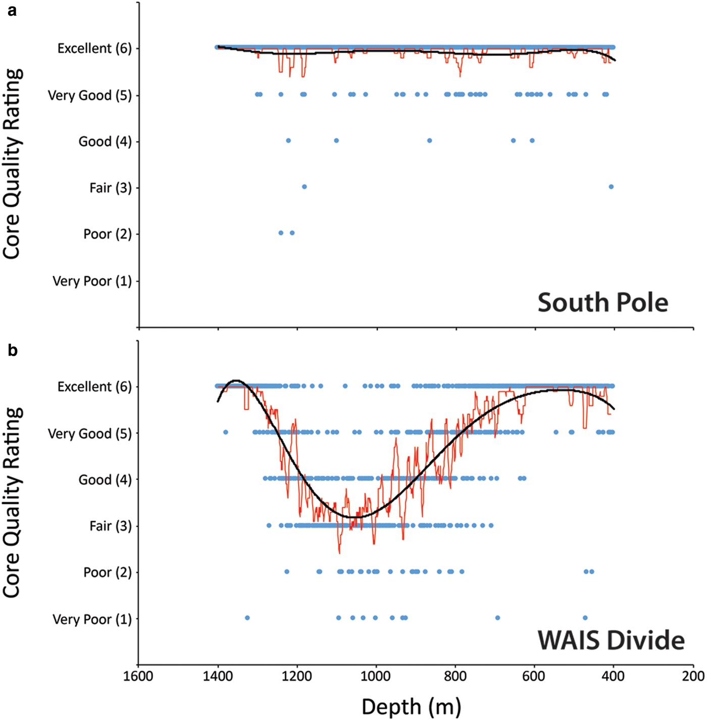
Fig. 7. In-field qualitative assessment of ice core quality vs depth in the (a) SPICEcore and (b) the WAIS Divide ice core (Souney and others, Reference Souney2014) for comparison. A change in ice quality is not clearly seen in the SPICEcore, whereas a change in ice quality is clearly seen in the WAIS Divide ice core. Excellent: 0–1 breaks/no fractures; very good: 0–2 breaks/90% no fractures; good: 0–3 breaks/50% no fractures; fair: >10 cm without fractures; poor: >10 cm without through fractures; very poor: <10 cm without through fractures. The thin red line is a ten-period moving average and the thick black line is a sixth-order polynomial of the core quality rating (blue circles).
It is not entirely clear why the recovered ice at the South Pole exhibited such minimal brittle behavior, however, based on the physical understanding of grain growth (e.g. Gow, Reference Gow1969) and observations of recovered ice from other Antarctic sites (Neff, Reference Neff2014) we suspect it relates in part to the unique combination of snow accumulation rates and surface air temperatures at the South Pole. Grain growth within polar firn is controlled by the total time to transformation (i.e. accumulation and burial rates), and by the growth rate (which is largely controlled by temperature) (Gow, Reference Gow1969). For these reasons, the lower average surface temperatures and higher accumulation rates at the South Pole favor both a thicker firn column and smaller overall grain (and bubbles) sizes at the depth of bubble trapping (Gow, Reference Gow1968, Reference Gow1969). Smaller grains and bubbles may serve to inhibit the mechanisms necessary to initiate brittle-ice fracturing upon ice recovery. Initial observations of thin-section samples taken from SPICEcore (Personal communication from Joan Fitzpatrick, 2020) do indicate a deep bubble close-off depth (~130 m), very fine grain sizes (<4 mm2), and a distinct lack of chessboard subgrain boundaries (a potential pathway for brittle ice fracture propagation seen in other ice cores (e.g. Fitzpatrick and others, Reference Fitzpatrick2014)). In addition, handling the ice on-site at such low ambient temperatures, combined with improved overall handling procedures, and use of elastic netting, all also likely played a part in reducing potential brittle-ice behavior. A more detailed investigation of the physical properties of SPICEcore is currently underway in order to better address these questions.
Core storage trench
The 6.4 m (21 ft) long, 4.6 m (15 ft) wide and 3 m (10 ft) deep underground core storage trench was excavated with a Caterpillar 953 track loader and covered with a wooden roof (Fig. 8a). The storage trench was in-line with the drill trench and accessed via a set of stairs at the end of the drill trench. Stairs, rather than a ramp, were utilized to save valuable space in both the drill and core storage trenches. The core storage trench served a dual role: it served as a work area to pack and store the core boxes containing the five 1 m long sections of ice cores, and also housed wooden shelves for storing the 2.49 m long core tubes of brittle ice overwinter (Figs 8b and c). The roof was constructed of timbers and plywood and equipped with a 1.4 m (4 ft 8 in) × 1.23 m (4 ft) ceiling hatch (Figs 8a–c). A ladder lift repurposed from the construction industry was used to lift the packed core boxes through the ceiling hatch and onto the surface outside of the drill tent (Fig. 8d). The ladder lift system was easy to set-up, required minimal maintenance and worked very well in safely transporting the core boxes out of the storage trench. Because of its underground nature, the temperature inside the storage trench was notably colder than the drilling trench, with temperatures ranging between −30 and −35°C inside the storage trench during the field season. After concerns that a plywood floor would be too slippery, it was decided to leave the floor of the storage trench bare. The storage trench was purposely sized for storing 550 m of brittle ice on shelving each season, rather than holding an entire season's worth of drilled ice, and because of this, it was necessary to ship non-brittle ice back to McMurdo Station mid-season.
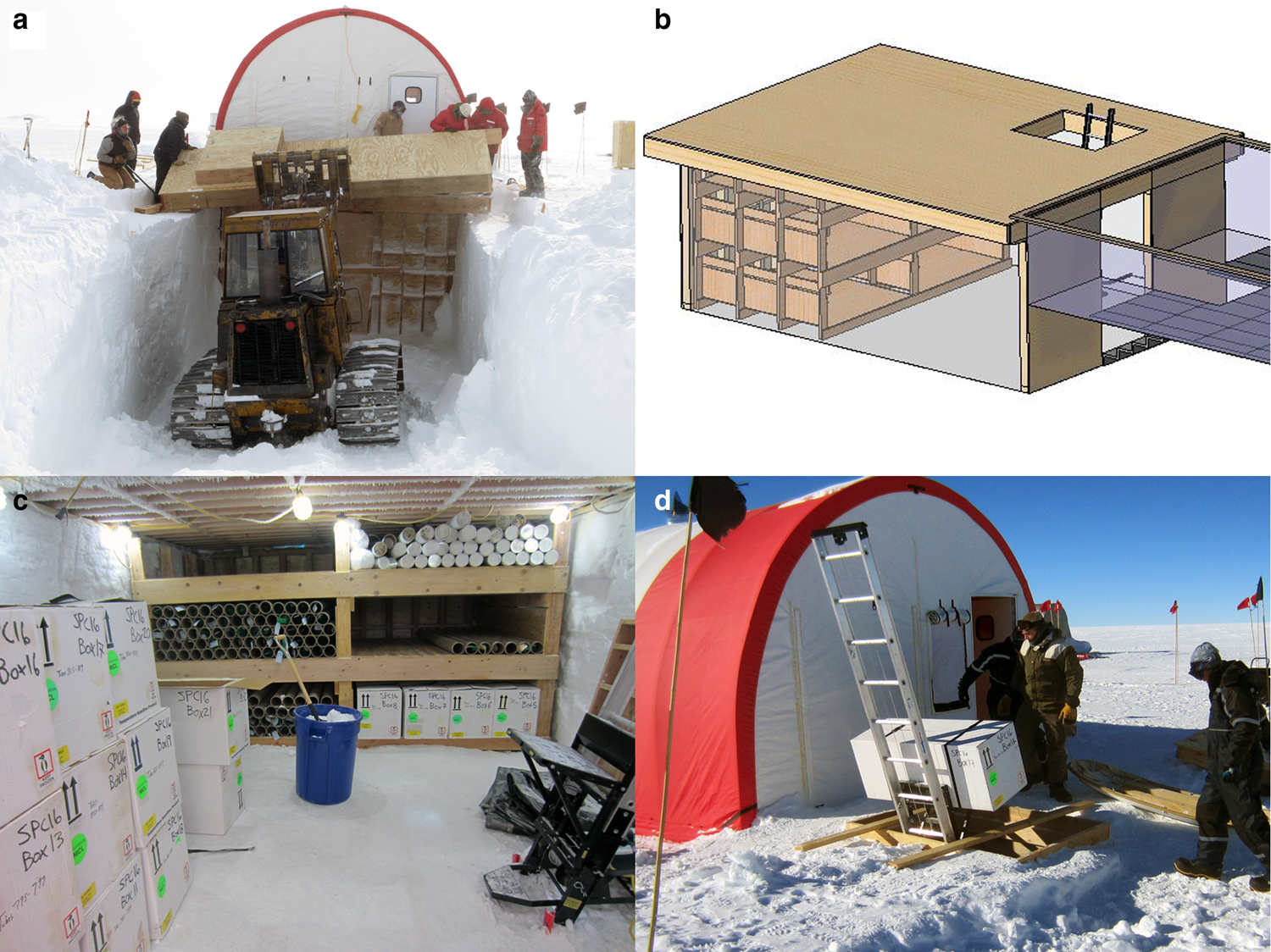
Fig. 8. (a) A Caterpillar 953 track loader moves the roof of the underground core storage trench into place. (b) Computer-aided design model of the core storage trench. (c) View of the core storage trench during the 2016/17 field season. The white core boxes contain non-brittle ice ready for shipment back to the USA. The brown tubes on the shelves contain 2 m long sections of brittle ice that were drilled the previous season and left onsite to relax over the winter. Also shown is the ladder lift system (right foreground) used to lift the core boxes out of the storage trench. (d) An ice core box is lifted out of the core storage trench and onto the surface outside of the drill tent with the ladder lift system.
Shipping
The packed ice core boxes were flown from South Pole Station to McMurdo Station via cold-deck (e.g. unheated aircraft cabin) LC-130 aircraft (see Core transportation section). Because of the necessity to use the LC-130 aircraft, the methods and procedures used to ship the core boxes were designed around the use of a 463L Master Pallet – or Air Force Pallet (AFP) – that weighed 130 kg (290 lb) when empty and ~2100 kg (~4600 lb) when fully loaded with ice core boxes.
After the core boxes were removed from the underground storage trench via the ladder lift (Fig. 8d), eight core boxes would then be palletized by hand onto a single wood skid, configured with two rows of four core boxes (Fig. 9a). The core boxes were placed on their sides when building the wood skids to reduce the overall height of the skid and to maximize airflow in the SAFECORE container (see Core transportation section). After banding, a fork-equipped skid-steer loader was then used to move four wood skids onto a single AFP (Fig. 9a). The four wood skids were covered with a 25.4 mm (1 in) thick insulating blanket before being secured to the AFP with cargo straps. Two temperature loggers were placed on each AFP, one on the inside of the blanket and one on the outside of the blanket. A fork-equipped track loader was then used to lift the AFP onto a cargo sled (Fig. 9b) and then it pulled the loaded cargo sled on the groomed road to South Pole Station (Fig. 9c). Once at South Pole Station, the cargo sled was stored under unused steel arches located at the end of the station's cargo berms (Fig. 9d) until it was time to load the AFPs onto an LC-130. The cargo sled of core boxes was stored under the steel arches, rather than at South Pole Station, because it kept the ice out of the way of normal station activity. Also, the steel arches protected the core boxes from direct sun exposure and also funneled the wind, providing natural air conditioning. The cores were typically stored under the steel arches for 10–72 h before being loaded onto an LC-130.
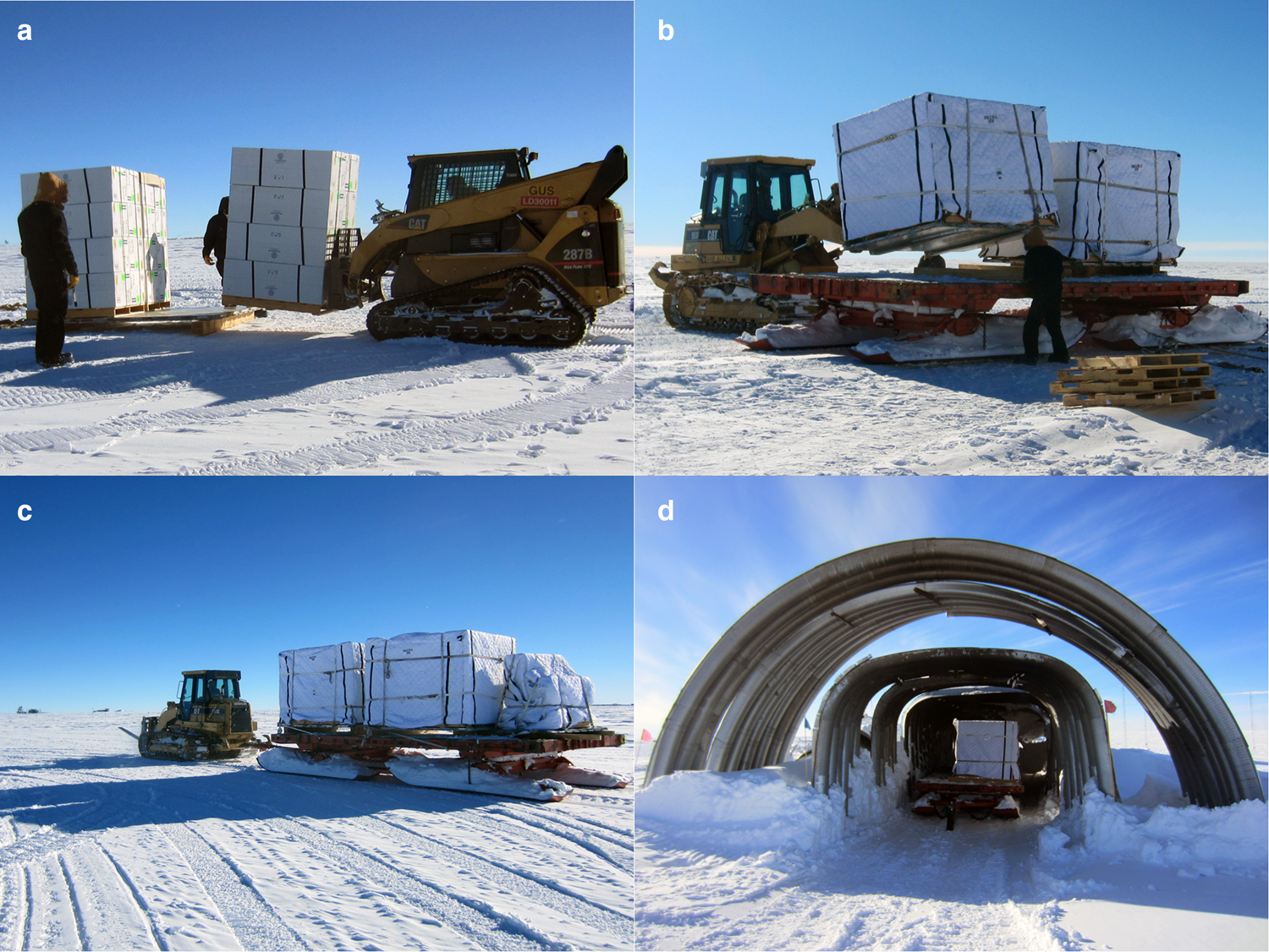
Fig. 9. (a) A fork-equipped skid-steer loader moves a wood skid containing eight core boxes onto an AFP. (b) A fork-equipped track loader lifts an AFP containing 32 core boxes (four wood skids, with eight core boxes per wood skid) onto a cargo sled. (c) The fork-equipped track loader pulls the cargo sled of ice core boxes back to South Pole Station. (d) The cargo sleds are stored in the shade under arches until being shipped to McMurdo on a cold-deck LC-130.
Fieldwork chronology
The following is an overview of each field season's activities. Details of the drilling operation and the IDD design have been described previously (Johnson and others, Reference Johnson, Shturmakov, Kuhl, Mortensen and Gibson2014; Johnson and others, Reference Johnson2020).
2013/14 Season
Antarctic Support Contract (ASC) personnel prepared the drill site and the road leading to it and conducted a ground-penetrating radar survey at the site to ensure that there were no underground obstructions to drilling. ASC also excavated, backfilled and compacted to 1.5 m depth a 91 × 91 m area centered on the borehole location. Drill fluid and borehole casing were pre-staged in McMurdo Station.
2014/15 Season (first drilling season)
Seven drillers arrived at South Pole Station on November 8. Two core handlers and one lead scientist arrived at South Pole Station on November 13. The field activities began with the excavation of the drilling and core storage trenches and the establishment of drill camp structures, followed by the installation of the IDD and the overlying drill tent. Two 10 m long (101 mm diameter) firn cores (SPC HA1 and SPC HA2) were hand-augered just outside of the drill tent to make up for ~5 m of lost ice from the main core due to the excavation of the drill trench. Drilling of the main core with the IDD started on December 8 at 5 m depth and finished on January 24 at 736 m depth. Beginning on December 22, drilling and core handling operations were carried out in a 20 h d−1, six days per week schedule with two 10 h shifts per day. Firn and ice cores from 5 m to 305 m depth were shipped on the first cold-deck flight of the season, freeing up most of the storage trench for construction of the shelving to hold the anticipated brittle ice. Ice from 305 m to 585 m depth was shipped on the second cold-deck flight of the season. Ice from 585 m to 735 m remained in the storage trench to ‘winter-over’ (Table 1). Four days were spent packing cargo and winterizing the drill site.
2015/16 Season (second and final drilling season)
A field team of seven drillers, two core handlers and one lead scientist arrived at South Pole Station on November 25. The drilling started on December 3 at 736 m in the brittle ice zone and reached the final drilling depth of 1751 m on January 23, surpassing the project's original goal of 1500 m by 251 m. Drilling and core handling operations were carried out in a 24 h d−1, 6 d w−1 schedule with three 8 h shifts per day. The 2014/15 season's ‘winter-over’ ice from 585 m to 735 m was cut, packed and shipped to the USA, along with the 2015/16 season's newly drilled ductile ice from 1078 m to 1478 m (Table 1). The season's newly drilled brittle ice from 735 m to 1077 m remained onsite in the core storage trench to ‘winter-over’ (Table 1). Ten fugitive gas samples were collected from the bottom sections of the core. Three days were spent packing cargo and winterizing the drill site.
2016/17 Season
A field team of two drillers, two core handlers and one science lead arrived at South Pole Station on November 23. One other scientist joined the field team one week into the season to log the borehole. The season's primary scientific objective was to cut, pack and retrograde all of the ice drilled and left onsite in the storage trench during the 2015/16 season: brittle ice from 735 m through 1078 m and the ductile ice from 1478 m through 1751 m. Nearly all the ice that shipped out this season was ‘excellent’ or ‘very good’ quality, as was the norm for the project (Fig. 7). Other science activities during the season included two temperature logs, one video log and two dust logs of the borehole. Drill site shut-down activities started while borehole logging was underway. The drill tent was removed, all equipment was packed for retrograde, and the drill trench, drill slot and core storage trench were backfilled with snow. The borehole casing was extended ~1.2 m (4 ft) above the snow surface (Fig. 10). The drill fluid was left in the borehole to facilitate future borehole logging or sampling (e.g. Allison and others, Reference Allison2019).
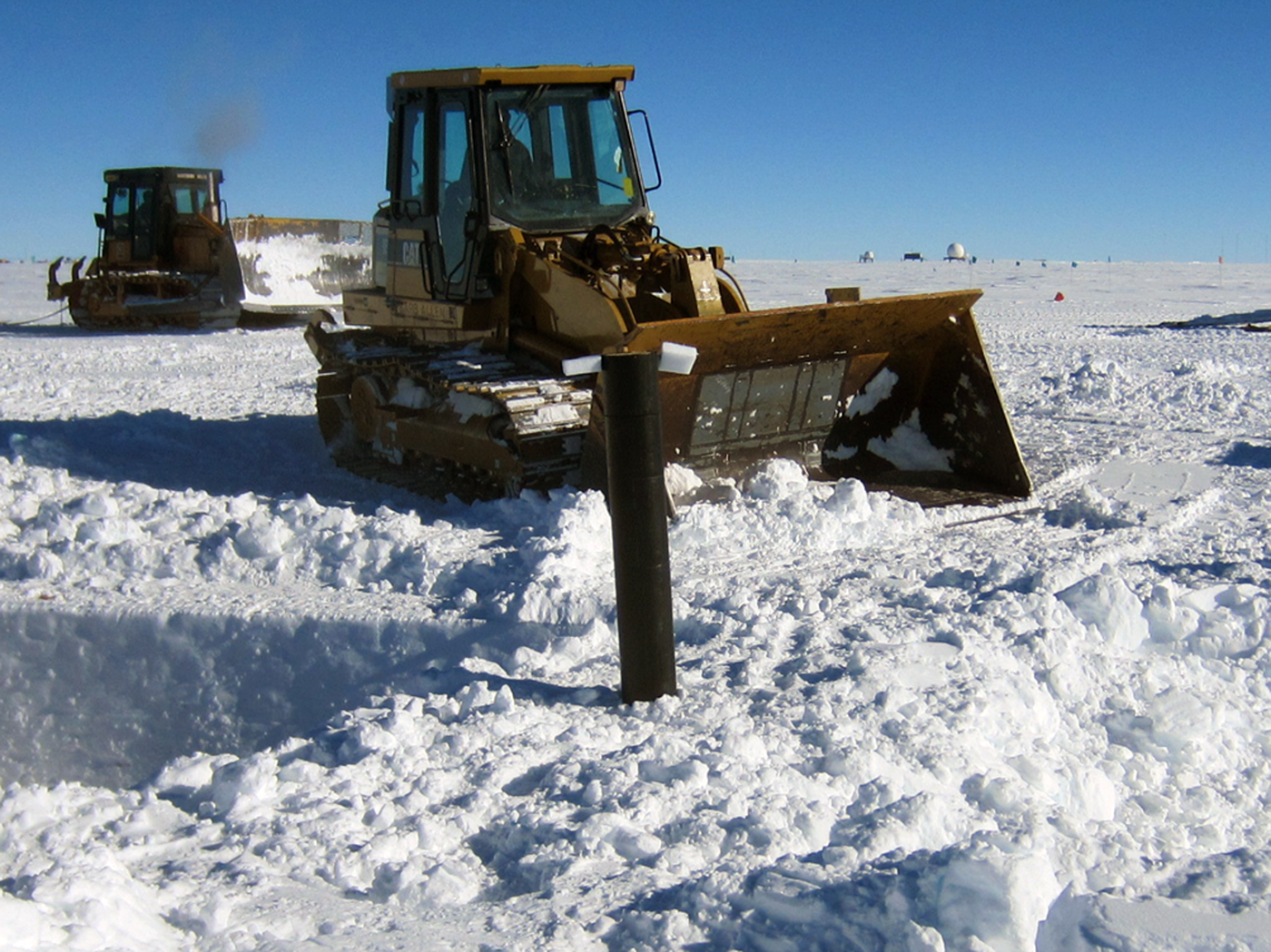
Fig. 10. At the conclusion of the project, the drill trench, drill slot and core storage trench were backfilled with snow. The borehole casing (image center) was extended ~1.22 m (4 ft) above the snow surface and the drill fluid was left in the borehole to facilitate future borehole logging or sampling.
Core transportation
There were three transportation legs involved in the retrograde of the ice cores from South Pole Station to the NSF-ICF in Denver, Colorado: (1) South Pole Station to McMurdo Station via air; (2) McMurdo Station to Port Hueneme, California, via sea; (3) and Port Hueneme to the NSF-ICF via land. Approximately 600 m of ice was transported in each of the three-field seasons (Table 1).
South Pole Station to McMurdo Station
The packed ice cores were flown from South Pole Station to McMurdo Station via cold-deck (e.g. unheated aircraft cabin) Hercules LC-130 airlift operated by the Air National Guard (ANG). The LC-130 flight time between South Pole Station and McMurdo Station is ~3 h. Six cold-deck flights were utilized during the project (two cold-deck flights each season), with the flights typically departing South Pole Station at ‘night’ for arrival during the coldest part of the day in McMurdo. An in-flight observer also accompanied the ice on four out of six cold-deck flights. After landing on the Pegasus blue-ice runway, a USAP Science Cargo team transferred the palletized ice cores into McMurdo Station's freezers within 2 h.
Even though South Pole Station is one of the USAP's main hubs for science and logistics activities, complete with a skiway and numerous LC-130 flights scheduled inbound from McMurdo weekly, the scheduling and preparation for cold-deck flights proved challenging throughout the project. Flight cancellations because of mechanical issues or aircraft unavailability, coupled with the occasional weather cancellation, were frequent. Compounding the problem was the ANG's no-passenger policy on cold-deck flights (an in-flight observer was allowed), which made cold-deck flights difficult to schedule during periods of limited flight availability. Despite these challenges, all of the ice was successfully shipped to McMurdo Station each season in time to meet the mid-January resupply vessel deadline.
McMurdo Station to Port Hueneme
In February, at the end of the USAP austral summer field season, the palletized ice cores were transferred from McMurdo Station's freezers into refrigerated shipping containers for subsequent transport to Port Hueneme, California, via the USAP's Military Sealift Command-chartered annual resupply vessel MV Ocean Giant. The ice-strengthened container vessel reaches Port Hueneme for retrograde offload in mid-March. This is the riskiest transportation leg for the ice cores, not only because it is the longest transportation leg, but also because the refrigerated shipping containers typically cannot be accessed once they are loaded onto the vessel. Once the vessel is at sea, it is usually impossible to fix a broken refrigerated container or to physically transfer the ice cores out of a broken refrigerated container and into a new one. For this reason, the USAP's SAFECORE refrigerated shipping containers were utilized.
Originally designed and procured to support the WAIS Divide ice core project (Souney and others, Reference Souney2014), the SAFECORE shipping containers are equipped with fully redundant cooling and power generation systems. The 12.19 m (40 ft) long containers automatically switch to their backup refrigeration unit, or generator, in the event of a loss of performance. The units can run for as long as three days on a full generator tank if power is lost on the cargo vessel or onshore while the container is in transit. The SAFECORE containers were operated at −30°C and equipped with telemetry to allow their location, temperature and operational status to be monitored remotely during vessel transport. As an additional safety precaution, an ASC refrigeration technician accompanied the SAFECORE containers on the resupply vessel. During vessel transport, the −30°C SAFECORE containers were not accessed, but their temperature was monitored.
Port Hueneme to NSF-ICF
Once the USAP resupply vessel reached Port Hueneme, the SAFECORE containers were loaded onto flatbed semi-trailer trucks and driven ~1800 km (1100 mi) to the NSF-ICF in Denver, Colorado. As an added safety precaution, the ASC refrigeration technician and the USAP cargo supervisor shadowed the flatbed semi-trailer truck in their own vehicle in case the semi-trailer truck encountered any problems. Once at the NSF-ICF, the ice cores were unloaded from the SAFECORE containers and transferred into the NSF-ICF's −36°C main archive freezer. The ice remained in the archive freezer until it was time for core processing (Fig. 11).

Fig. 11. The retrograded ice cores from the 2014/15 field season sit safely inside the main archive freezer at the NSF-ICF in Denver, Colorado. The temperature inside the main archive freezer is −36°C. Each white box contains five 1 m long sections of the ice core.
Core processing at the NSF-ICF
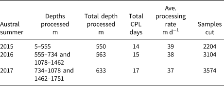
The NSF-ICF is an NSF-funded facility operated by the US Geological Survey for storing, curating and studying meteoric ice cores recovered from the glaciated regions of the world. In addition to its −36°C main archive freezer, the NSF-ICF also houses a 340 cubic meter (12 000 cubic foot) exam room held at −24°C for core processing and sample cutting. The examination room contains a series of stations around the perimeter and in the center of the room. A roller track is installed around the perimeter of the examination room to allow the smooth transfer of 1 m long sections of the ice core from one station to the next without the need to physically pick-up the ice. After each season in which ice was shipped back to the NSF-ICF (Tables 1 and 2), a core processing line (CPL) was held in the examination room to re-log the core to assign final top and bottom depths and to cut samples from the ice core according to an agreed-upon cut plan (Fig. 12). The CPLs were held during the summers of 2015, 2016 and 2017, and between 550 and 633 m of ice were processed during each CPL. After the first CPL in 2015, the cut plan was modified to provide two equal-area sticks for water stable-isotope analysis (Fig. 12). Typically, 10–12 people staffed the CPL, and 38 m of ice were processed per day on average (Table 2). Over 10 300 samples have been cut to date from the ice core and distributed to 16 individually funded scientists from 13 US institutions for analysis at their respective institutions or laboratories. Very few analyses on the ice core were conducted at the NSF-ICF. Figure 13 shows the flow chart and stations used for the 2016 and 2017 CPLs. The processing and sampling of the ice during the CPLs closely followed established methods (Souney and others, Reference Souney2014) as described below.
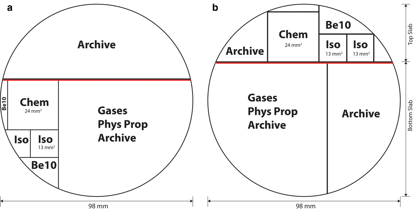
Fig. 12. Cross-section of the 98 mm diameter ice core showing the generalized cut plan used at the NSF-ICF during the (a) 2015 CPL (5–555 m depth) and the (b) 2016 and 2017 CPLs (555–1751 m depth). After the 2015 CPL, the cut plan was modified to provide two equal-area sticks for water stable-isotope analysis (Iso). Over 10 300 samples have been cut to date and distributed to 16 individually funded investigators from 13 US institutions for analysis. The thick red line represents the ice removed by the planer before the electrical properties are measured on the core. Chem = chemistry; Iso = water stable isotopes; Be10 = beryllium-10; Phys Prop = physical properties.
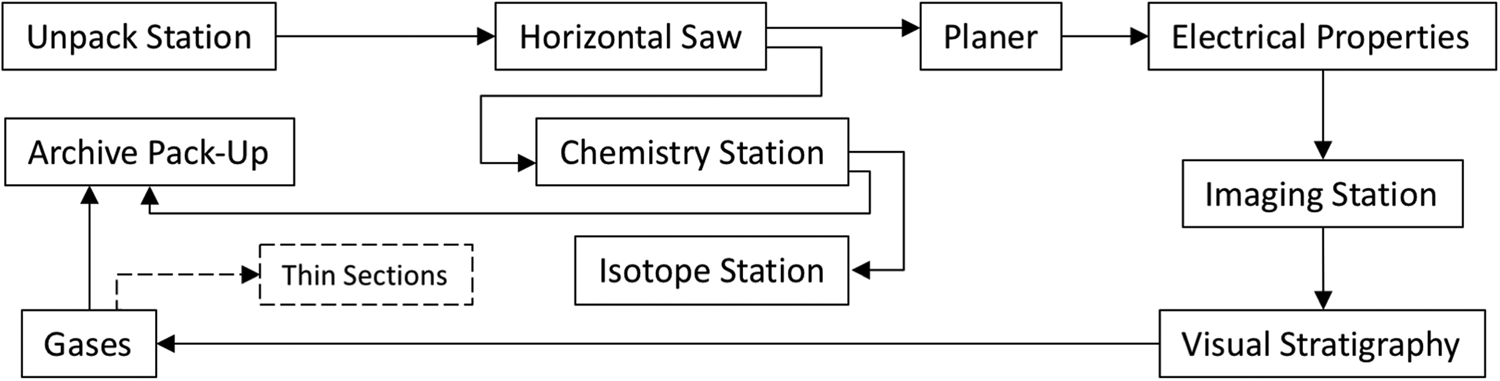
Fig. 13. Generalized flow chart for the 2016 and 2017 CPLs at the NSF-ICF.
Table 2. Summary of CPL activities at the NSF-ICF
Unpack station
The purpose of the ‘Unpack' station was to prepare each 1 m long section of ice core for the CPL and to assign final top and bottom depths using a laser pointer-equipped Balluff digital distance-measuring system. The ice core was first unpacked from its core tube and wiped with a dry absorbent towel to remove any residual drilling fluid. Most of the cores had minor amounts of residual drilling fluid on their surface, and the netted cores typically had more drilling fluid than the non-netted cores. The core was then fitted to the previous ice core and placed in a clamping tray in preparation for cutting. For the brittle ice, the netting was removed by carefully cutting the netting along the long axis of the core with a pair of scissors, and then the brittle ice core was fitted to the previous brittle ice core and placed in a clamping tray in preparation for cutting. The ice core logging procedure by Hvidberg and others (Reference Hvidberg, Steffensen, Clausen, Shoji and Kipfstuhl2002) was once again used to measure the length of the ice core and assign final depths. The only difference from the logging in Antarctica was that a laser pointer-equipped Balluff digital distance-measuring system was used instead of a 2 m long measuring stick. The 1 m ice core top and bottom depths were then compared to the measurements taken at South Pole Station and the new data recorded into the NSF-ICF's computerized inventory database. The difference between the depths assigned at South Pole Station and the NSF-ICF was <0.5% for each meter, and the final bottommost depth assigned to the entire ice core was within millimeters of one another. Any breaks or notable features in the ice were also documented and entered into the database. Sample cards that indicated the specific cuts needed for the given 1 m long section of ice core were then printed and placed with the ice core in the tray. As each cut was made on the ice core, a unique sample card accompanied the particular sample for identification.
Horizontal saw
At the ‘horizontal saw’ station, one cut along the core's long axis split the ice core into a top slab and a bottom slab (Figs 12a and b). The top slab was 28 mm thick and continued to the chemistry station for further cutting (Fig. 13). The 70 mm thick bottom slab continued down the CPL to the planer and electrical properties stations (Fig. 13).
Chemistry station
At the ‘chemistry’ station, a bandsaw was used to cut a 24 mm × 24 mm continuous flow analysis (CFA) stick out of the top slab. The CFA stick was used for chemistry and microparticle analysis and packaged in cleanroom grade, ultra-low outgassing polyethylene lay-flat tubing (Winski and others, Reference Winksi2019). The top slab's remaining smaller wing piece was archived, and the larger wing piece continued down the CPL to the isotope sampling station.
Isotope sampling station
At the ‘isotope sampling’ station, a bandsaw was used to cut two 13 mm × 13 mm sticks for water stable-isotope analysis. During the 2016 CPL, the two sticks went to different laboratories. One stick was packed into a transparent 19 mm (0.75 in) square acrylic tube to retain the ice's integrity during transport and subsequent handling for continuous water stable-isotope analysis by CFA. The second stick was cut into 500 mm long samples and placed into clean bottles for discrete water stable-isotope analysis. During the 2017 CPL, both sticks went to the same laboratory and were packed into the transparent 19 mm (0.75 in) square acrylic tubes for continuous water stable-isotope analysis (Jones and others, Reference Jones2017; Kahle and others, Reference Kahle, Holme, Jones, Gkinis and Steig2018). During the 2016 CPL, the remaining larger wing piece went to a laboratory for beryllium-10 analysis, and during the 2017 CPL, the piece was archived. During both CPLs, the smaller wing piece was typically collected in a barrel to be melted and used as isotope standard water.
Planer station
At the ‘planer' station, 2 mm of ice was removed from the surface of the bottom slab to remove saw marks and prepare the surface for the electrical properties, imaging and visual stratigraphy stations. The planer was a standard 305 mm (12 in) woodworking bench planer modified to move horizontally on rails above the core.
Electrical properties
At the ‘electrical properties' station, the electrical properties of the ice core were measured on the planed surface of the bottom slab via the electrical conductivity measurement (ECM; Hammer, Reference Hammer1983). Measurements were made with alternating-current ECM and direct-current ECM via a robotically controlled system in which two electrodes in contact with the ice were moved along the long axis of the ice core. Multiple tracks were made at different horizontal positions across the core (Fudge and others, Reference Fudge, Taylor, Waddington, Fitzpatrick and Conway2016). The electrical properties measurements were used to identify annual layers and volcanic peaks in the ice, thus determining the age of the ice (Winski and others, Reference Winksi2019).
Imaging station
At the ‘imaging' station, a color image of the polished flat surface of the bottom slab was taken to archive the ice core's visual appearance digitally. The station utilized an optical line-scanning system that scanned the cores at a spatial resolution of 0.06 mm (160 pixels cm−1) (McGwire and others, Reference McGwire2008). The line-scanning system was fully integrated into the CPL, with top and bottom depths automatically assigned to each image based on the measurements entered into the NSF-ICF inventory database at the unpack station. Imaging was conducted on the same piece of ice used at the electrical properties station and was not cleaned or planed again after the ECM measurement. The imaging camera was focused a few millimeters below the surface of the ice, and a dark field method was used for lighting. Using a dark field method, the top surface is not illuminated so most surface imperfections, like any scratch marks that may be left by the ECM, were usually not seen in the images.
Visual stratigraphy
Using clear trays, the bottom slab was slid into a dark booth for analysis. In the booth, each core was illuminated from below to reveal internal features and stratigraphy. For some cores, particularly from depths >~250 m, side-directed tray lighting from a scatter–diffuser was often more effective at revealing features. All noteworthy internal features, stratigraphy, physical properties, and also any breaks, spalls, chips or fractures in the cores were documented by hand in 1 m long paper logbooks. The depths of all noted features were recorded to the nearest millimeter. Additional details of the visual stratigraphy methods are described in Fegyveresi and others (Reference Fegyveresi, Fudge, Winski, Ferris and Alley2019).
Gas sampling station
At the ‘gas sampling’ station, a bandsaw and dry-cut circular saw were used to cut discrete samples of different lengths from the bottom slab for a variety of gas analyses. Physical properties samples for vertical and horizontal thin sections were also typically cut in this area of the examination room.
Archive pack-up
About one-third or more of every 1 m long section of the ice core was retained for future studies. Each remaining part of the two slabs of the core was inventoried and then placed in its own clearly labeled lay-flat bag. The ice was then returned to its core tube and placed inside the NSF-ICF's −36°C archive freezer for long-term storage.
Final comments
The proximity of the SPICEcore drill site to South Pole Station reduced the logistical footprint of the project and provided an opportunity to demonstrate the capability of the newly developed IDD. The IDD's core handling line was easy to install/uninstall and worked as intended, allowing for the efficient logging and handling of the drilled ice without compromising core quality.
The ice core exhibited minimal brittle behavior, which was likely due to site characteristics, and to a lesser extent, to drill technology and core handling procedures. The elastic netting was used to ensure that if any breakage of the brittle ice occurred after drilling, the broken fragments would be contained in place. In retrospect, the ice displayed little brittle behavior, and the netting was likely not needed for large sections of the brittle zone. The netting made it more difficult to remove the drilling fluid from the cores in the field, and when unpacked at the NSF-ICF, there was more residual drill fluid on the netted-cores than on the non-netted ones.
During its journey from South Pole Station to the NSF-ICF, the core boxes were handled as a palletized unit, eliminating the need to move individual core boxes. Every core box contained a temperature logger, which was activated at the time of packing in the storage trench at the South Pole and remained active until the core box reached the NSF-ICF in Denver, CO, USA. Temperature loggers were also included on the outside of each AFP of core boxes. The temperature records from all loggers were reviewed, and no abnormalities were observed.
The core was logged twice using the ice core logging procedure outlined by Hvidberg and others (Reference Hvidberg, Steffensen, Clausen, Shoji and Kipfstuhl2002): first in Antarctica immediately after drilling and a second time at the NSF-ICF. The close agreement between the two sets of logs is a testament to the robustness of Hvidberg and others (Reference Hvidberg, Steffensen, Clausen, Shoji and Kipfstuhl2002) ice core logging procedure.
During each of the three CPLs at the NSF-ICF, between 550 and 633 m of ice were processed within a three week period, with 38 m of ice processed per day on average. The CPLs went very smoothly, and there were no problems processing, cutting or archiving any of the ice. About one-third or more of every 1 m long section of the ice core was retained for future studies and archived in the NSF-ICF's −36°C main archive freezer.
Acknowledgements
This work was supported by the US NSF grants 1142517, 1141839 and 1142646. We appreciate the support of the US Ice Drilling Program for designing and building the Intermediate Depth Drill and its core handling system and for drilling the South Pole ice core; the National Science Foundation Ice Core Laboratory (NSF-ICF) and the US Geological Survey for designing and operating the core processing system at the NSF-ICF and for curating the ice core; the Antarctic Support Contract for logistics support in Antarctica; the 109th New York Air National Guard for airlift support in Antarctica; and M. Davis and the entire USAP science cargo team for their cargo support. SPICEcore data are archived at the US Antarctic Program Data Center.


 Open access