


Introduction
Lithium-ion batteries (LIBs) have made a revolution in portable electronic devices over decades and have been used in electric vehicles, hybrid electric vehicles, and grid energy storage systems due to their long cycle life and high energy density [Reference Tarascon and Armand1]. However, LIBs using intercalation chemistry are gradually approaching their theoretical limit, and cannot meet the increasing demand for higher energy density and lower cost from end users in automotive industry and stationary applications [Reference Thackeray, Wolverton and Isaacs2]. Therefore, it becomes imperative to develop new-generation battery technologies that satisfy these requirements. Among various potential systems, sodium–selenium (Na–Se) batteries have drawn much attention, because of the large abundance and low cost of sodium and decent energy density of Se [Reference Abouimrane, Dambournet, Chapman, Chupas, Weng and Amine3]. As a cathode material, Se provides a moderate gravimetric capacity of 678 mA h/g and a high volumetric capacity of 3270 mA h/cm3 and possesses a high electronic conductivity of 1 × 10⁻³ S/m (versus 5 × 10⁻²⁸ S/m for S) [Reference Xu, Liu, Amine, Chen and Amine4, Reference Yang, Yin and Guo5, Reference Gu, Tang, Liu and Hou6]. These advantages of Se have stimulated growing research in developing Li–Se and Na–Se batteries over the past years.
Na–Se batteries are still in their infant stage and face a significant challenge, i.e., shuttle effect, which was caused by polyselenide dissolution from Se cathodes. Shuttle effect not only leads to the loss of active Se material but also results in the corrosion of Na metal anode, causing low Coulombic efficiency (CE) and rapid performance decay in Na–Se batteries [Reference Xu, Liu, Amine, Chen and Amine4, Reference Yang, Yin and Guo5, Reference Gu, Tang, Liu and Hou6, Reference Li, Wei, Manthiram, Feng and Ma7]. To date, several approaches have been developed to address shuttle effect problem, and the confinement of Se into porous carbon matrix is one of the most promising strategies [Reference Zeng, Zeng, Jiang, Wei, Li, Yang, Zhu and Yu8, Reference Li, Liu, Yao, Cheng, Li, Li, Wolverton, Wu and Dravid9, Reference Ding, Zhou, Zhang, Stephenson, Li, Karpuzov and Mitlin10, Reference Luo, Wang, Suo, Mao, Fan and Wang11, Reference Wang, Jiang and Manthiram12, Reference Luo, Xu, Zhu, Liu, Zheng, Liu, Langrock and Wang13, Reference Yao, Chen, Xu, Zeng, Yang, Ye, Liu, Wu and Yu14]. For example, Wang and co-workers prepared Se/mesoporous carbon at 600 °C under vacuum, and the Se/mesoporous carbon cathode delivered a specific capacity of 340 mA h/g after 380 cycles in Na–Se batteries [Reference Luo, Xu, Zhu, Liu, Zheng, Liu, Langrock and Wang13]. Moreover, several recent works have explored various metal organic frameworks (MOF) (such as zinc-glutamate MOF, ZIF-67, and ZIF-8) [Reference Dong, Chen, Xia, Yu, Song, Wu, Deng, Hu, Hasan, Li, Wang, Chen and Su15, Reference Yang, Wang, Yu and Rogach16, Reference Xu, Liu, Li, Hu, Dai, Zhang, Li, Liu and Xu17] as starting materials to synthesize porous carbon as hosts for Se cathodes in Na–Se batteries. Although the space confinement has been effective in improving the overall performance of Se cathode, polyselenide dissolution still occurs in Na–Se batteries using porous carbon confined Se cathode. In general, Na–Se batteries show more severe shuttle effect than their Li–Se counterparts [Reference Gu, Tang, Liu and Hou6]. For Li–Se batteries using carbonate-based electrolytes, Se undergoes a one-step reaction from Se to Li2Se, without the formation of soluble polyselenide intermediates and is featured with one single plateau in its charge–discharge curves [Reference Xu, Liu, Amine, Chen and Amine4, Reference Zeng, Zeng, Jiang, Wei, Li, Yang, Zhu and Yu8]. However, for Na–Se batteries, Goodenough and co-workers [Reference Xin, Yu, You, Cong, Yin, Du, Guo, Yu, Cui and Goodenough19] found that during the first discharge process, Se in microporous carbon (MPC) underwent stepwise reduction to Na2Se, with the formation of soluble intermediate polyselenides (Na2Sex) in Na–Se batteries. One main reason could be due to the larger ionic radius of Na+ (102 pm) than that of Li+ (74 pm), which might cause larger volume change in the Se cathode and alter reaction pathways of Se in Na-based batteries [Reference Wang, Zhang, Deng, Tang, Deng, Hu and Liu18, Reference Xin, Yu, You, Cong, Yin, Du, Guo, Yu, Cui and Goodenough19]. Therefore, it is necessary to develop and use multiple strategies to stabilize Se cathode for high-performance Na–Se batteries.
In addition to the space confinement strategy, surface coating has also been explored as an effective approach to address the shuttle effect problem in S-based [Reference Wei, Li, Cha, Zheng, Yang, McDowell, Hsu and Cui20, Reference Lee, Black, Yim, Ji and Nazar21, Reference Li, Zhang, Zheng, Seh, Yao and Cui22, Reference Li, Liu, Wang, Banis, Xiao, Li, Sham and Sun23] and Se-based batteries [Reference Zhang, Xiong, Guo, Zhang, Yang, Wu, Liu and Wang24, Reference Ma, Li, Yang, Mi, Luo, Deng, Yan, Zhang, Lin and Ren25]. Ideally, the surface coating layer should be thin and uniform to reduce the dissolution of intermediate products, while allowing fast Li ion and electron diffusion. In recent years, atomic layer deposition (ALD) has emerged as a powerful technique to realize uniform surface coatings on the anode and cathode for LIBs [Reference Liu and Sun26, Reference Lu, Liang, Sun, Sun, Wu, Hou, Sun and Yuan27, Reference Knoops, Donders, van de Sanden, Notten and Kessels28] and next-generation batteries (such as Na-ion, Li–S) [Reference Meng29, Reference Yan, Li, Bai, Song, Xiong, Zhao, Li and Lu30], to prevent unwanted interfacial reactions and improve the overall performance of batteries. Compared with other coating techniques, ALD provides precise control over the thickness of thin films at the nanoscale level and excellent uniformity on even high aspect ratio substrates [Reference George31, Reference Miikkulainen, Leskelä, Ritala and Puurunen32], promising it great potential for surface and interface engineering in various battery systems. However, the potential of ALD for interface design in Na–Se batteries is yet to be fully exploited.
Herein, we reported the utilization of nanoscale Al2O3 surface coating by ALD to stabilize the Se cathode for high-performance Na–Se batteries with carbonate-based electrolytes. MPC prepared by pyrolysis of polyvinylidene fluoride (PVDF) was adopted to fabricate MPC/Se cathode. It was found that Al2O3 surface coating effectively suppressed the polyselenide dissolution from the MPC/Se cathode, thus reducing the loss of Se active material and improving the overall performance of Na–Se batteries.
Results and discussion
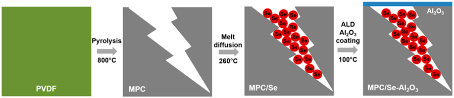
MPC was synthesized by the direct pyrolysis of PVDF at 800 °C in a nitrogen environment and used as the Se host without any further activation process. Previous work has shown that MPC prepared at this condition exhibited the highest surface area and dominant microporous feature, which were important merits for confining Se in the cathode [Reference Xu, Hou, Chu, Cao and Yang33, Reference Xu, Hou, Duan, Cao, Chu and Yang34, Reference Aboonasr Shiraz, Zhu, Liu, Sun and Liu35]. High-resolution transmission electron microscopy (HRTEM) characterization discloses the disordered structure of the as-synthesized MPC [Fig. 1(a)]. After the Se impregnation, MPC/Se composite displays irregular shapes with particle sizes of about 10–200 μm [Fig. 1(b)]. Raman spectra of MPC and MPC/Se [Fig. 1(c)] show two vibration peaks at about 1350 and 1600 cm−1, which are assigned to D band (disordered carbon originating from sp 3 carbons) and G band (hexagonal carbon), respectively [Reference Yang, Xin, Yin, Ye, Zhang and Guo36, Reference Li, Yuan, Yi, Liu and Huang37]. It should be noted that MPC/Se composite displays no obvious peaks at 143 and 235 cm−1 for crystalline bulk Se [Reference Fang, Zhou, Pei, Li and Cheng38]. Raman analysis reveals that there is no bulk Se in the MPC/Se composite, and all Se are mainly encapsulated in the micropores of MPC. Se content in MPC/Se composite was determined to be 48 wt% by thermogravimetric analysis. Al2O3 coating was deposited on the MPC/Se electrode by ALD using 10 cycles and 20 cycles, and the prepared samples were designated as MPC/Se-10Al2O3 and MPC/Se-20Al2O3, respectively. As seen in Figs. 1(d) and 1(e), MPC/Se-10Al2O3 retains the morphology of MPC/Se and turns into slightly darker in the scanning electron microscope (SEM) image due to non-conductive nature of Al2O3 coating (as also shown for MPC/Se–20Al2O3 and MPC/Se-100Al2O3 in Fig. SI-1). Elemental mapping by energy-dispersive X-ray spectroscopy (EDS) in Fig. 1(f) shows the uniform distribution of Al and O elements on the surface of MPC/Se cathode. The thickness of Al2O3 on MPC/Se-10Al2O3 and MPC/Se-20Al2O3 is about 1 nm and 2 nm, respectively, based on the growth rate of Al2O3 on standard Si wafers [Reference George31, Reference Miikkulainen, Leskelä, Ritala and Puurunen32]. The preparation process for MPC/Se-Al2O3 is illustrated in Fig. 1(g).

Figure 1: (a) HRTEM image of MPC; (b) SEM image of MPC/Se; (c) Raman spectra of MPC, MPC/Se, and bulk Se; (d, e) SEM images and (f) EDX elemental mapping of MPC/Se coated with 10 ALD cycle Al2O3 (MPC/Se-10Al2O3); and (g) schematic illustration of the preparation process for MPC/Se-Al2O3.
The influence of Al2O3 coating on electrochemical performance of MPC/Se cathode is studied in Na–Se batteries between 0.5 and 3 V at 0.1 C, and the results are shown in Fig. 2. As shown in Fig. 2(a), MPC/Se-10Al2O3 and MPC/Se-20Al2O3 exhibit an initial capacity of about 1050 mA h/g, similar to the pristine MPC/Se. After the 1st cycle, however, there is a dramatic difference in the specific capacity of the MPC/Se cathodes with and without Al2O3 coating. The discharge capacity in the 2nd cycle was 534 mA h/g, 664 mA h/g, and 639 mA h/g for MPC/Se, MPC/Se-10Al2O3 and MPC/Se-20Al2O3, respectively. The capacity drop from the 1st cycle to the 2nd one in all the three samples could be ascribed to the formation of SEI film and the decomposition of electrolytes on the MPC/Se cathode [Reference Luo, Xu, Zhu, Liu, Zheng, Liu, Langrock and Wang13]. For MPC/Se cathode, the capacity decreases gradually from 534 mA h/g in the 2nd cycle to 446 mA h/g after 80 cycles and then undergoes rapid decay to 396 mA h/g until 100 cycles. In contrast, MPC/Se-10Al2O3 could still deliver a specific capacity of 570 mA h/g after 100 cycles. The capacity retention of MPC/Se cathode from the 2nd cycle to 100th cycle was elevated from 73 to 86% by using Al2O3 coating. Moreover, the specific capacity and cycling performance of MPC/Se-20Al2O3 are lower than those of MPC/Se-10Al2O3 but better than those of pristine MPC/Se cathode. The thickness of Al2O3 coating on Se/MPC cathode was also optimized in 1 M NaClO4 and ethylene carbonate/diethyl carbonate (EC:DEC) without fluoroethylene carbonate additive (Fig. SI-2). Further increase in Al2O3 coating more than 20 cycles causes an obvious decrease in the specific capacity. The reason could be due to the insulating nature of Al2O3 coating, which might slow down the diffusion of Li ions through the SEI layer [Reference Liu and Sun26, Reference Lu, Liang, Sun, Sun, Wu, Hou, Sun and Yuan27, Reference Knoops, Donders, van de Sanden, Notten and Kessels28, Reference Meng29]. This result suggests the importance of Al2O3 coating thickness for achieving optimal protection effect in Se cathodes.

Figure 2: (a) Cycling performance of MPC/Se, MPC/Se-10Al2O3, and MPC/Se-20Al2O3 measured at 0.1 C (1 C = 678 mA/g); charge–discharge profiles of MPC/Se and MPC/Se-10Al2O3 in the (b) 1st cycle, (c) 50th cycle, and (d) 100th cycle; (e) rate capability of MPC/Se and MPC/Se-10Al2O3; (f) cycling stability of MPC/Se-10Al2O3 tested at 0.1 C in the first 10 cycles and 0.5 C afterward. The electrolyte is 1 M NaClO4, EC:DEC + 3% FEC.
Figures 2(b)–2(d) present charge/discharge curves of the MPC/Se and MPC/Se-10Al2O3 in the 1st, 50th, and 100th cycle tested at 0.1 C. As shown in Fig. 2(b), both MPC/Se and MPC/Se-10Al2O3 exhibit one obvious plateau during the discharge and charge process, which is characteristic of micropore-confined Se [Reference Luo, Xu, Zhu, Liu, Zheng, Liu, Langrock and Wang13, Reference Yao, Chen, Xu, Zeng, Yang, Ye, Liu, Wu and Yu14, Reference Dong, Chen, Xia, Yu, Song, Wu, Deng, Hu, Hasan, Li, Wang, Chen and Su15, Reference Yang, Wang, Yu and Rogach16, Reference Xu, Liu, Li, Hu, Dai, Zhang, Li, Liu and Xu17]. CE in the 1st cycle is calculated to be 51.4% and 60.9% for MPC/Se and MPC/Se-10Al2O3, respectively, implying that Al2O3 coating reduces the side reaction between Se electrode and the electrolyte. Moreover, it is found from Figs. 2(b)–2(d) that Al2O3 coating also minimizes the polarization of MPC/Se cathode during the discharge and charge process. For example, midpoint-voltage differences in the 50th and 100th cycles are 0.30 and 0.46 V for MPC/Se and 0.22 and 0.24 V for MPC/Se-10Al2O3 [Figs. 2(c) and 2(d)], indicating enhanced reaction kinetics of MPC/Se by Al2O3 coating. The improved capacity and kinetics in MPC/Se-10Al2O3 could be resulted from the protective effect of nanoscale Al2O3 coating, which alleviates polyselenide dissolution and reduces the deposition of solid polyselenides. Moreover, a previous study on Na-ion batteries has shown that the Al2O3 coating on the electrode might convert to a stable Na–Al–O layer, which served as a Na buffer layer to facilitate Na ion diffusion [Reference Han, Liu, Jia, Chen, Wan, Weadock, Gaskell, Li and Hu39, Reference Jung, Kim, Choi and Han40]. As a result of the improved kinetics, the MPC/Se-10Al2O3 also exhibits better rate capability than MPC/Se cathode [Fig. 2(e)]. MPC/Se-10Al2O3 could deliver a specific capacity of 544.4 mA h/g, 518.5 mA h/g, 458.3 mA h/g, 422.5 mA h/g, and 343.8 mA h/g at 0.1 C, 0.2 C, 0.5 C, 1 C, and 2 C, respectively, while MPC/Se shows a specific capacity of 477.7 mA h/g, 463.3 mA h/g, 370.1 mA h/g, 353.3 mA h/g, and 245.7 mA h/g under the same condition. At last, the cycling test at 0.5 C shows that MPC/Se-10Al2O3 can maintain a specific capacity of 320 mA h/g after 100 cycles [Fig. 2(f)]. From the results in Fig. 2, it can be concluded that ALD Al2O3 coating effectively improves the specific capacity, cycling stability, and rate capability of the MPC/Se cathode in Na–Se batteries.
To find out the underlying mechanism for performance improvement by ALD Al2O3 coating, electrochemical impedance spectroscopy (EIS) measurement was performed on MPC/Se and MPC/Se-10Al2O3 before and after 100 cycles, and the results are presented in Fig. 3. As seen in Fig. 3(a), both MPC/Se and MPC/Se-10Al2O3 display one semicircle in the high-frequency region, which corresponds to the charge transfer resistance (R CT) at the electrode–electrolyte interface, and one inclined line in the low-frequency region, which is interpreted as the finite length Warburg impedance [Reference Lee, Kim, Nitta, Eom, Lee, Wu, Lin, Zdyrko, Il Chod and Yushin41]. The smaller R CT in MPC/Se-10Al2O3 might be due to the improved physical contact between the electrode material and Al current collector by ultrathin Al2O3 coating directly on the electrode, which allows faster electron diffusion [Reference Jung, Cavanagh, Riley, Kang, Dillon, Groner, George and Lee42]. The Nyquist profiles of MPC/Se and MPC/Se-10Al2O3 after cycling present one semicircle (R CT) in the high-frequency region, Warburg impedance in the low-frequency domain, and another semicircle in the medium-frequency region, which can be assigned to the Li-ion diffusion resistance at the SEI (R SEI) [Reference Lee, Kim, Nitta, Eom, Lee, Wu, Lin, Zdyrko, Il Chod and Yushin41]. The Nyquist profiles are fitted by using the equivalent circuit inserted in Fig. 3(b) to obtain EIS parameters for MPC/Se and MPC/Se-10Al2O3 (Table I). From Table I, it is evident that R SEI reduces from 40.9 to 20.2 Ω, while R CT decreases from 90.6 to 68.6 Ω for the MPC/Se cathode with Al2O3 coating. EIS analysis clearly indicates that Al2O3 surface coating positively affects the formation of SEI layers and reduce charge transfer and Li-ion diffusion resistances on the MPC/Se cathode.

Figure 3: The Nyquist profiles of MPC/Se and MPC/Se-10Al2O3 (a) before cycling and (b) after 100 cycles (inset shows the equivalent circuit used to fit the Nyquist plots).
TABLE I: EIS parameters obtained by fitting the Nyquist plots of MPC/Se and MPC/Se-10Al2O3 after 100 cycles.

The morphologies of MPC/Se and MPC/Se-10Al2O3 after 100 cycles are examined, and the typical SEM images are depicted in Fig. 4. From Figs. 4(a)–4(c), it can be found that the cycled MPC/Se electrode is covered with thick SEI layers and has much less porosity than the uncycled one. The thick SEI layers could originate from the decomposition of electrolytes and the deposit of solid polyselenides (Na2Se and Na2Se2) on MPC/Se surface due to shuttle effect. In contrast, the cycled MPC/Se-10Al2O3 cathode possesses much thinner SEI layers. As a result, the sharp edges in the MPC/Se particles are still visible [Fig. 4(f)] compared with these before battery cycling [Fig. 1(e)]. EIS and post-cycling analysis suggest that nanoscale Al2O3 surface coating facilitates the formation of robust and thin SEI layers on the MPC/Se electrode, which are believed to account for the reduced R CT and Na-ion diffusion resistance at the electrode–electrolyte interface.

Figure 4: SEM images of (a–c) MPC/Se electrode and (d–f) MPC/Se-10Al2O3 electrode after 100 cycles.
Glass fibers recovered from cycled MPC/Se and MPC/Se-10Al2O3 cells are further examined to understand the polyselenide dissolution, and the typical SEM pictures are shown in Fig. 5. Glass fiber facing to the MPC/Se electrode is deposited with micro-sized solid particles [circled in Fig. 5(a)]. EDX analysis confirms strong signals from Na and Se elements, implying that the solid particles might be Na2Se and/or Na2Se2. In contrast, glass fiber from the MPC/Se-10Al2O3 cell retains their original fibrous structure and shows no obvious large solid deposits [Figs. 5(c) and 5(d)]. Figure 5 provides an additional evidence for the suppressed polyselenide dissolution from the MPC/Se cathode by Al2O3 surface coating.

Figure 5: SEM images of glass fibers recycled after 100 cycles from (a, b) the MPC/Se cell and (c, d) the MPC/Se-10Al2O3 cell [inset in (b) shows the EDX spectrum of the solid particles].
Conclusions
ALD nanoscale Al2O3 surface coating was successfully applied to solve polyselenide dissolution problem and enable MPC/Se cathode for stable and high-capacity Na–Se batteries. The thickness of Al2O3 coating had a profound influence on the overall performance of MPC/Se cathode. The optimal electrochemical performance of MPC/Se cathode was achieved by using 10 ALD cycles of Al2O3 coating. Al2O3-coated MPC/Se cathode exhibited a reversible discharge capacity of 664 mA h/g in the 2nd cycle and 570 mA h/g after 100 cycles. Moreover, Al2O3 coating on MPC/Se cathode also improved the rate capability and reduced the polarization during charge/discharge processes. The enhanced performance was due to that nanoscale Al2O3 coating suppressed the dissolution of polyselenides, induced the formation of stable and thin SEI layers, and thus decreased the R CT at the electrode–electrolyte interface.
Methodology
Preparation of MPC, MPC/Se, and MPC/Se-Al2O3
PVDF [(–CH2CF2–)n, MW: 64.035 g/mol; Alfa Aesar] was put into a tube furnace (Lindberg/Blue M Mini-Mite™) and heated up to the temperature of 800 °C with a heating rate of 10 °C/min and kept for 1 h under the inert gas environment (nitrogen 99.999%) to perform the pyrolysis. The thermal decomposition of PVDF led to the formation of micropores in MPC structure. Black products collected after pyrolysis were MPC and no further activation on MPC was required. The MPC/Se composite was prepared by a melting diffusion method. Briefly, in a mortar, sublimed selenium powder, −100 mesh (99.5%; Sigma-Aldrich), and MPC with the same weight ratio of 50:50 were mixed with each other for 1 h and sealed in a 50 mL stainless steel autoclave. This process was conducted in a glove box workstation under the protection of argon atmosphere with H2O and O2 levels below 0.1 ppm. The autoclave was put into a furnace followed by heat treatment at 260 °C for 12 h. The melting diffusion method used the capillary force to diffuse Se into microspores of MPC. To obtain the cathode electrode, 80 wt% of MPC/Se composite, 10 wt% of carbon black (MTI Co.), and 10 wt% of sodium alginate (0.5 wt% aqueous solution; Ward’s Science Co., Ltd.) were mixed in planetary mortar to form a uniform slurry, which was then pasted to an Al foil current collector by using a doctor blade. The electrode was kept at room temperature (RT) overnight for initial water evaporation and then underwent complete drying in a vacuum oven at 60 °C for 12 h. Subsequently, the electrode was cut into round disks with a diameter of 12.7 mm for coin-cell assembly.
The coating of Al2O3 on MPC/Se electrode was performed at 100 °C by alternatively supplying trimethylamine (TMA) and H2O into a commercial ALD reactor (GEMStar™ XT Atomic Layer Deposition Systems; Arradiance). Thickness of Al2O3 on MPC/Se cathode was adjusted by using 10 and 20 ALD cycles, and the prepared sample was designated as MPC/Se-10Al2O3 and MPC/Se-20Al2O3, respectively.
Structural and electrochemical characterizations of MPC and MPC/Se composites
SEM equipped with EDS (Tescan MIRA3) was used to examine the morphology and structure of different samples. The electrochemical properties of the MPC/Se composites were evaluated in CR 2032 coin cells by using Na foil as the counter electrode. The assembly of coin cells was performed in a glove box workstation with argon protecting gas (99.999%). Each coin cell was composed of one MPC/Se electrode as the cathode, Na metal as the anode, and glass fiber as the separator. The electrolyte was 1 M NaClO4 in a mixture of EC/DEC (1:1 v/v) with 3 vol% FEC additive. The cycling performance of the coin cells was tested in a voltage window of 0.5–3 V on a Neware BTS 4000 battery testing system.
Supplementary material
To view supplementary material for this article, please visit https://doi.org/10.1557/jmr.2019.356
Acknowledgments
This work was supported by the Nature Sciences and Engineering Research Council of Canada (NSERC), Canada Foundation for Innovation (CFI), BC Knowledge Development Fund (BCKDF), and the University of British Columbia (UBC).


