


Impact Statement
Fabrication of optical components has not changed significantly in the past century, and is based on mechanical grinding, machining and polishing that rely on complex and expensive infrastructure. Furthermore, such mechanical methods present challenges in the fabrication of large or geometrically complex components. Modern manufacturing methods such as 3-D printing, while capable of producing nearly arbitrary structures, cannot provide the required surface quality for optical applications. In this work, we leverage the fundamental physics of interfacial phenomena and introduce the concept of fluidic shaping – an approach for rapid fabrication of a wide range of optical components at any size, with nanometric surface quality. The method replaces mechanical processing, eliminating the dependence on heavy infrastructure, and provides new fabrication capabilities for both research and industrial applications. In addition, this work constitutes the first step in analytically describing the steady-state configurations of fluidic interfaces under different constraints.
1. Introduction
Lenses are a fundamental component of any optical system, from microscopes to telescopes, holograms, eye-glasses, data storage devices, lasers and many more. Fabrication of lenses or lens moulds relies on mechanical processing such as grinding and machining, followed by polishing of the optical surfaces (Reference Roeder, Guenther and ZimmermannRoeder, Guenther, & Zimmermann, 2019). The demand for high-quality surfaces requires specialized and expensive equipment, and the fabrication of non-standard optical surfaces remains challenging (Reference Bielke, Beckstette, Kuebler, Lasser, Mullany, Pollmann and WangBielke et al., 2004; Reference Roeder, Guenther and ZimmermannRoeder et al., 2019). It is natural to consider three-dimensional (3-D) printing technologies as a potential platform for lens prototyping, yet thus far, the quality of prints is inadequate for optical applications (Reference Heinrich and RankHeinrich & Rank, 2018), and complex post-processing is needed in order to achieve the required surface quality (Reference Vaidya and SolgaardVaidya & Solgaard, 2018). Furthermore, 3-D printing time is proportional to the volume being printed (Reference Oropallo and PieglOropallo & Piegl, 2016) and thus large lenses or a large number of lenses require a substantial time to fabricate, making this approach inadequate for industrial-scale fabrication.
An alternative approach leverages the smooth liquid--air interface of small polymer droplets to produce high surface-quality lenses (Reference Cruz-Campa, Okandan, Busse and NielsonCruz-Campa, Okandan, Busse, & Nielson, 2010; Reference Karunakaran, Jagirdar, Paul and MukherjiKarunakaran, Jagirdar, Paul, & Mukherji, 2016, Reference Karunakaran, Tharion, Dhawangale, Paul and Mukherji2018; Reference Lee, Upadhya, Reece and PhanLee, Upadhya, Reece, & Phan, 2014; Reference Marthelot, Strong, Reis and BrunMarthelot, Strong, Reis, & Brun, 2018; Reference Roy, Yadav, Arul, Khanna and GhatakRoy, Yadav, Arul, Khanna, & Ghatak, 2016). However, the size of such lenses is restricted by the capillary length of the liquid polymer (representing the relative importance of gravitational to surface tension forces), which for most liquids at standard conditions is <2.5 mm (Reference de Gennes, Brochard-Wyart, Quéré, de Gennes, Brochard-Wyart and Quéréde Gennes, Brochard-Wyart, & Quéré, 2004). As the diameter of the droplet approaches the capillary length, gravitational forces become dominant. On top of a horizonal surface, large droplets will be flattened by gravity, resulting in a loss of their spherical shape. On an inverted surface, gravity deforms the suspended droplets into an aspherical shape, yet this approach suffers from the same size limitation (Reference Lee, Upadhya, Reece and PhanLee et al., 2014). On large scales, techniques such as spin casting rely on centrifugal forces in order to deform a curable liquid into a paraboloid. However, these active approaches require significant infrastructure, and are limited to parabolic surfaces only (Reference DierickxDierickx, 2000, p. 224).
We here present a simple method for rapid fabrication of a variety of high surface-quality lenses that is not limited by size and does not require specialized equipment. As illustrated in Figure 1, the method is based on the injection of a curable lens liquid into an immiscible immersion liquid environment. Under such conditions, in addition to gravity, the liquid polymer experiences a buoyancy force. When the density of the immersion liquid is set to match that of the polymer, neutral buoyancy conditions are achieved, effectively eliminating the influence of gravity and the dependence on the capillary length. The shape of the resulting lens is determined solely by the injected volume and the geometry of any bounding surfaces in contact with the lens liquid. After the desired shape is obtained, the lens is cured (e.g. polymerized or cross-linked) using standard methods (e.g. photoactivation, thermal setting), and can be removed from the immersion liquid. Due to the natural smoothness of the interface between the lens liquid and the immersion liquid, the quality of the resulting lens is dictated by the molecular polymerization scale and does not require polishing.

Figure 1. Schematic illustration of the fluidic shaping method, where an optical liquid is injected into a bounding frame submerged in an immersion liquid environment. The injected volume, the relative density of the liquids and the shape of the bounding frame determine the shape of the resulting lens. (a) A thin ring-shaped surface used to produce a positive spherical lens. (b) A thick ring-shaped surface used to produce a negative spherical lens. (c) A rectangular pad with two walls, used to produce a cylindrical lens. (d) The same rectangular pad with less injected volume, results in a saddle lens.
We demonstrate the fabrication of plano-convex, plano-concave, bi-convex, bi-concave, bi-focal, meniscus lenses, in addition to non-standard surfaces such as cylindrical lenses, saddle lenses and aspheric lenses. We also show simple fabrication of doublet lenses based on the combination of several polymers.
2. Theory
Consider a liquid chamber filled with an immersion liquid of density  ${\rho _{im}}$, containing a ring-shaped bounding surface with radius ${R_0}$ and vertical thickness d, positioned at height ${h_0}$ from the bottom of the chamber (see Figure 2). A curable lens liquid of density ${\rho _{lens}}$, which is injected into the bounding surface, is pinned at the boundaries forming two interfaces with the immersion liquid, whose positions are given by ${h^{(t)}}(r)$ and ${h^{(b)}}(r)$ (see supplementary movie S1 available at https://doi.org/10.1017/flo.2021.1 for demonstration of the injection process). For the pinning to occur, the only requirement is for the lens liquid to have higher adhesion to the inner side of the bounding surface than that of the immersion liquid. We assume isothermal conditions such that the interfacial tension between the liquids, $\gamma $, remains constant.

Figure 2. Schematic illustration of the configuration used for experiments and modelling. The set-up consists of a liquid lens injected into a ring-shaped bounding surface which is submerged within an immersion liquid. The outlined segment under the lens liquid marks the location of a thin cylindrical enclosure (not in the image), on top of which the ring-shaped bounding surface is located. Once the liquid lens is formed, it encloses immersion liquid inside the cylindrical region. Adding or removing immersion liquid from the enclosed volume allows us to inflate or deflate the lens from below, making it possible to create meniscus-type lenses.
In the above described configuration, in addition to gravity, the lens liquid experiences a buoyancy force that acts through its boundaries in the opposite direction. The capillary length for such a system is defined by  ${\ell _c} = \sqrt {\gamma /\Delta \rho g} $, where $\Delta \rho = |{{\rho_{lens}} - {\rho_{im}}} |$, and g is Earth’s gravity. Thus, if the density of the immersion liquid is set to match that of the lens liquid, the capillary length goes to infinity and interfacial forces dominate over gravity at all scales.
The steady-state shapes of the top and bottom interfaces can be found by minimizing the free-energy functional of the system, given by
 \begin{align}E &= 2{\rm \pi} \gamma \int_0^{{R_0}} \left(\sqrt{1 + {{(h_r^{(t)})}^2}} + \sqrt {1 + {{(h_r^{(b)})}^2}} - \frac{{\Delta \rho g}}{{2\gamma }}({{({h^{(t)}})}^2} - {{({h^{(b)}})}^2}) \right.\nonumber\\ &\qquad \qquad \qquad + \left.\frac{{{\lambda_1}}}{\gamma }(h^{(t)} - {h^{(b)}}) + \frac{{{\lambda_2}}}{\gamma }{h^{(b)}}\right) r\,\textrm{d}r.\end{align}
 The first two terms under the integral represent the surface energy of the top and bottom surfaces, which are proportional to their interfacial areas and the surface tension. The third term represents the gravitational energy of the lens liquid volume after integration in the vertical coordinate z and the azimuthal coordinate  $\theta $. The last two terms represent the physical constraints on the system, namely, the volume of the lens liquid and the enclosed volume, with ${\lambda _1}$ and ${\lambda _2}$ being the Lagrange multipliers. Minimization of E yields a set of coupled Euler--Lagrange equations, which in terms of ${h^{(t)}}$ and ${h^{(b)}}$ take the form
 \begin{equation}\left. {\begin{array}{*{20}{c}} {\left( {\dfrac{{\Delta \rho g}}{\gamma }{h^{(t)}} - \dfrac{{{\lambda_1}}}{\gamma }} \right)r + \dfrac{{rh_{rr}^{(t)} + h_r^{(t)} + {{(h_r^{(t)})}^3}}}{{{{(1 + {{(h_r^{(t)})}^2})}^{3/2}}}} = 0,}\\ {\left( {\dfrac{{\Delta \rho g}}{\gamma }{h^{(b)}} - \dfrac{{{\lambda_1}}}{\gamma } + \dfrac{{{\lambda_2}}}{\gamma }} \right)r - \dfrac{{rh_{rr}^{(b)} + h_r^{(b)} + {{(h_r^{(b)})}^3}}}{{{{(1 + {{(h_r^{(b)})}^2})}^{3/2}}}} = 0,} \end{array}} \right\}\end{equation}
where  ${h_r}$ and ${h_{rr}}$ the first and second radial derivatives. The additional conditions, which include the pinning of the liquid at the boundaries and the volume constraints, are given by
 \begin{equation}{h^{(b)}}({R_0}) = {h_0},\;\;{h^{(t)}}({R_0}) = {h_0} + d,\;\;{V_{lens}} = 2{\rm \pi} \int_0^{{R_0}} {({h^{(t)}} - {h^{(b)}})r\,\textrm{d}r} ,\;\;{V_{enclosed}} = 2{\rm \pi} \int_0^{{R_0}} {{h^{(b)}}r\,\textrm{d}r},\end{equation}
where  $V_{lens}$ is the volume of the lens, and $V_{enclosed}$ is the volume enclosed underneath the lens.
3. Results
3.1 Spherical Lenses
At neutral buoyancy conditions (i.e.  $\Delta \rho = 0$) these equations reduce to the familiar Young–Laplace form, in which case ${h^{(t)}}(r)$ and ${h^{(b)}}(r)$ take the shape of perfectly spherical caps.
When the injected volume,  ${V_{lens}}$, is larger than the volume enclosed by the frame, ${V_0} = {\rm \pi}R_0^2d$, the lens liquid obtains a positive curvature (i.e. a convex lens). Panels (a)–(c) in Figure 3 demonstrate the ability to control the curvature of a positive lens by varying the injected volume. Panels (g)–(i) present similar results for a taller frame with ${V_{lens}} \lt {V_0}$, in which case the liquid interfaces protrude inward, yielding a negative (concave) lens.

Figure 3. Experimental images of spherical lenses produced using ring-shaped bounding surfaces. (a–c) Neutral buoyancy conditions with  ${V_{lens}} \gt {V_0}$ result in positive and symmetric spherical lenses, where the lens curvature is dictated by the injected volume. (d–f) Varying slightly the density of the immersion liquid for a fixed volume (here ${V_{lens}} \gt {V_0}$) results in asymmetric spherical lenses. (g–i) Neutral buoyancy conditions with ${V_{lens}} \lt {V_0}$ result in negative and symmetric spherical lenses, where, similarly to (a–c), the optical power can be controlled by the injected volume.
In the case of  $|{\Delta \rho } |\gt 0$ the up--down symmetry is broken by the additional buoyancy force, resulting in an asymmetric lens. However, as long as $|\Delta \rho |/{\rho _{im}} \ll 1$, the lens surfaces can still be well approximated as spheres. Panels (d)–(f) in Figure 3 show the shapes of a positive, fixed-volume lens, at various densities of the immersion liquid. The up--down symmetry can also be broken by varying the enclosed volume (see Figure 2), thus effectively inflating or deflating the lens liquid, resulting in meniscus-type lenses (see supplementary movie S2).
Once the lens liquid assumes its minimum energy shape, it can be solidified by standard methods. For polymers, it is particularly important to obtain uniform curing of the entire volume, to avoid stresses that would deform the lens. In addition, even under uniform curing, polymers undergo a change in density that leads to shrinkage that may also affect the shape of the final lens. In this work, we based our fabrication on thermal curing of polydimethylsiloxane (PDMS) and on UV curing of an optical adhesive (see supplementary information). At room temperature, curing of PDMS has been shown to achieve very low shrinkage (as low as 0.1%) (Reference Madsen, Feidenhans'l, Hansen, Garnæs and DirscherlMadsen, Feidenhans'l, Hansen, Garnæs, & Dirscherl, 2014), and correspondingly low changes in density. However, this process has the disadvantage of being fairly slow (several hours). Stresses and shrinkage under UV curing can be minimized primarily by using low intensity illumination (Reference NorlandNorland, 1995), and can still be completed within minutes. The number of optical-quality polymers is rapidly growing, fuelled by the desire to achieve lower weight and lower fabrication costs as compared to glass (Reference Piñón, Santiago, Vogelsberg, Davenport and CramerPiñón, Santiago, Vogelsberg, Davenport, & Cramer, 2017). These developments are primarily in the context of moulding-based fabrication, yet can be directly adapted by our method provided that an appropriate immersion liquid can be identified. The lens fabrication is then complete, and no additional processing steps are required.
Figure 4 presents a collection of solid lenses produced by the fluidic shaping method. Figure 4a shows the simplest case of a positive spherical lens produced using a ring-shaped bounding surface. Figure 4b shows a doublet lens produced by a two-step process, where a negative lens was first formed and then used as a base for a positive lens made from a different material (here coloured blue for better visualization). Figures 4c and 3d show respectively a saddle (toroidal) lens and a cylindrical lens created using different volumes injected into a bounding surface composed of a rectangular pad with two perpendicular walls at its sides (see details in supplementary information). Figure 4e shows a bi-focal lens produced by a two-step process, where a lens of one curvature was cut in half and used as part of a new bounding surface for a lens with a different curvature. Since both parts were made using the same polymer (PDMS) they formed a seamless single unit. Figure 4f shows a negative meniscus lens produced by increasing the enclosed volume below the lens. This type of lens is known to reduce spherical aberrations and is standardly used in the eyewear industry. Finally, Figure 4g shows a 200 mm spherical telescope lens (two orders of magnitude above typical capillary lengths), demonstrating the scale invariance of the fluidic shaping method.

Figure 4. Images of solid lenses produced using the fluidic shaping method. (a) A 50 mm diameter positive spherical lens. (b) A 30 mm diameter doublet lens produced by a two-step process, where a negative lens was used as a bounding frame for a positive lens made from a different material (here coloured blue for better visualization). (c) A 40 mm diameter saddle (toroidal) lens and (d) a 20 mm diameter cylindrical lens, produced using different lens liquid volumes injected into the same rectangular bounding surface. (e) A 30 mm diameter bi-focal lens produced by a two-step process, where a first lens was cut in half and used as part of a new bounding surface for a second lens with different curvature. (f) A 20 mm diameter negative meniscus lens produced by increasing the volume enclosed below the lens. (g) A 200 mm diameter spherical telescope lens.
The approach presented here produces lenses with extremely high surface quality. Our atomic force microscopy (AFM) measurements performed across a 20 × 20 μm area, yield surface roughness values of RMS = 1.15 nm and Ra = 0.84 nm (see details in supplementary information). It is important to emphasize that the surface quality is the direct result of the smoothness of fluidic interfaces and is therefore independent of the lens’ shape.
3.2 Aspheric Lenses
For small deviations from neutral buoyancy, symmetry is broken while the lens surfaces maintain their spherical shape. With further increase in  $\Delta \rho $, the liquid interfaces lose their spherical shape and buoyancy effects can no longer be neglected. In this case, we can define the following non-dimensional variables:
 \begin{align}R = r/{R_0},\;\;{H^{(t)}}(R) = {h^{(t)}}(R)/{h_c},\;\;{H^{(b)}}(R) = {h^{(b)}}(R)/{h_c},\;\;{p_1} = \frac{{{\lambda _1}{h_c}}}{{\gamma {\varepsilon ^2}}},\;\;{p_2} = \frac{{({\lambda _1} - {\lambda _2}){h_c}}}{{\gamma {\varepsilon ^2}}},\end{align}
where  ${h_c}$ is some characteristic vertical deformation length scale (e.g. the maximal value of ${h^{(t)}}(r) - {h^{(b)}}(r)$), and $\varepsilon = {({h_c}/{R_0})^2} \ll 1$. The governing equations now take the form
 \begin{equation}\left. {\begin{array}{*{20}{c}} {R(Bo{H^{(t)}} - {p_1}){{(1 + \varepsilon {{(H_R^{(t)})}^2})}^{3/2}} + RH_{RR}^{(t)} + H_R^{(t)} + \varepsilon {{(H_R^{(t)})}^3} = 0,}\\ {R(Bo{H^{(b)}} - {p_2}){{(1 + \varepsilon {{(H_R^{(b)})}^2})}^{3/2}} - RH_{RR}^{(b)} - H_R^{(b)} - \varepsilon {{(H_R^{(b)})}^3} = 0,} \end{array}} \right\}\end{equation}
where  $Bo = \Delta \rho gR_0^2/\gamma$ is the Bond number.
At leading order in  $\varepsilon $, substituting $x = R\sqrt {Bo} ,\;{P_i} = {p_i}/Bo$, the equations for the top and bottom interfaces take the form
 \begin{equation}xH_{xx}^{(t)} + H_x^{(t)} + x{H^{(t)}} = {P_1}x,\;xH_{xx}^{(b)} + H_x^{(b)} - x{H^{(b)}} ={-} {P_2}x,\end{equation}
where  ${H^{(i)}},\;i = t,b$ are the dimensionless functions describing the position of the liquid interfaces, and $x = (r/{R_0})\sqrt {Bo} $ is the non-dimensional radial coordinate.
The solutions to these equations are given by
 \begin{equation}{H^{(t)}} = {C_1} \, {J_0}(x)+ {P_1},\quad {H^{(b)}} = {C_2} \, {I_0}(x) + {P_2},\end{equation}
where  ${J_0}$ and ${I_0}$ are the zeroth-order Bessel and modified Bessel functions, respectively, and ${C_1},\;{C_2},\;{P_1},\;{P_2}$ are integration constants given by
 \begin{equation}\left.\begin{array}{c} {C_1} = \dfrac{{{h_c}{V_{lens}} - {\rm \pi}dBo + {h_c}\sqrt {Bo} ({h_c}{V_{enclosed}} - {\rm \pi}Bo{h_0})}}{{{\rm \pi} {h_c}\sqrt {Bo} (2{J_1}(\sqrt {Bo} ) - \sqrt {Bo} {J_0}(\sqrt {Bo} ))}},\\ {P_1} = \dfrac{{{h_0} + d}}{{{h_c}}} - {C_1}{J_0}(\sqrt {Bo} ), \\ {C_2} = \dfrac{{{h_c}{V_{enclosed}} - {\rm \pi}{h_0}Bo}}{{{\rm \pi} {h_c}\sqrt {Bo} (2{I_1}(\sqrt {Bo} ) - \sqrt {Bo} {I_0}(\sqrt {Bo} ))}},\\ {P_2} = \dfrac{{{h_0}}}{{{h_c}}} - {C_2}{I_0}(\sqrt {Bo} ). \end{array}\right\}\end{equation}
Equation (7) allows us to obtain a wide range of aspheric Bessel-shaped lenses, by controlling the injected volume, the enclosed volume and the Bond number of the system, as demonstrated in supplementary movie S3. It is important to note that these fluidic shapes are stable to significant disturbances even for values of  $Bo\sim 1$, as is demonstrated in supplementary movie S4, removing any time constraints from the polymerization process.
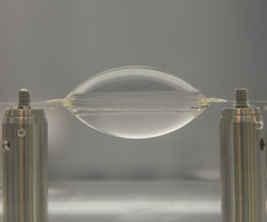
Figure 5 shows a very good agreement between agreement between the solutions for the top and bottom interfaces given by our theory and experimentally measured ones. In this specific experiment, the relevant physical parameters were  $\Delta \rho ={-} 6.5\;\textrm{kg/m}{\textrm{m}^3}$, $D = 87.2\;\textrm{mm}$, ${V_{lens}} = 48\;\textrm{ml}$ and $\gamma = 0.02\;\textrm{N/m}$. We note that our model does not have any fitting parameters, and the results are obtained directly by using actual physical parameters of the system.

Figure 5. A comparison of experimental results (image within the liquid container) to our theoretical predictions (dashed lines), for  $\Delta \rho ={-} 6.5$ kg/m3, $D = 87.2$ mm, ${V_{lens}} = 48$ ml and $\gamma = 0.02$ N/m, yielding good agreement with no fitting parameters.
5. Discussion and Conclusions
In conclusion, we have demonstrated a method for fluidic shaping of high-quality optical components, allowing for the first time rapid prototyping of optics. The method is scale invariant, and unlike its 3-D printing counterparts, the required fabrication time is not proportional to the volume being produced, thus allowing us to rapidly fabricate components of any size. In addition, the method is compatible with a wide range of curable liquids with various optical and mechanical properties. We identified four degrees of freedom for designing a fluidic optical component the volume of the component, the enclosed volume, the Bond number and the shape of the bounding surface. Importantly, the method does not require specialized equipment, and nanometre-scale surface quality is naturally achieved, without the need for a cleanroom environment, expensive equipment or complex post-processing (e.g. polishing).
The simplicity and affordability of this method make it a natural candidate to serve as platform for producing affordable eyewear. This is particularly important in countries where the required industrial infrastructure does not exist, preventing 2.5 billion people from access to corrective eyewear, costing the global economy over 1.2 trillion dollars each year (World Economic Forum, 2016). Another application of interest is at the opposite scale of size and cost large high-quality telescope lenses, which are currently produced in laborious and expensive processes. Lastly, one could envision the use of this technology for creation of large fluidic lenses in a microgravity environment (i.e. in orbit) where the immersion liquid becomes redundant. Under these conditions, the lens could remain in liquid form, allowing for dynamic control of its curvature.
In this work we focused primarily on an axisymmetric bounding surface, which can yield both spherical and aspherical lenses. However, the examples of the cylindrical and saddle lenses suggest that more general boundary conditions may lead to a wide variety of additional optical shapes. This may be of particular interest of the field of freeform optics where fabrication of non-spherical high-quality lenses remains a challenge (Reference Fang, Zhang, Weckenmann, Zhang and EvansFang, Zhang, Weckenmann, Zhang, & Evans, 2013). Numerical tools, such as the Surface Evolver (Reference BrakkeBrakke, 1992), could also be valuable for solving more complex configurations.
Acknowledgements
We thank O. Luria and B. Rofman for their assistance with AFM measurements and M. Elgarisi for his help in fabricating the 200 mm lens as well as producing the simulation videos.
Funding Statement
This project has received funding from the European Research Council under the European Union's Horizon 2020 Research and Innovation Programme, grant agreement 678734 (MetamorphChip).
Declaration of Interests
The authors declare no conflict of interest.
Author Contributions
V.F. and M.B. conceptualized the research, V.F conceived the fabrication method, performed the experiments and developed the model, V.F. and M.B analysed the data and wrote the manuscript.
Data Availability Statement
All data are available in the main text or the supplementary material.
Ethical Standards
The research meets all ethical guidelines, including adherence to the legal requirements of the study country.
Supplementary Material and Movies
Supplementary material and movies are available at https://doi.org/10.1017/flo.2021.1.


 Open access