


Introduction
Polymer nanocomposite materials exhibit tremendous flexibility in designing optimal properties for diverse applications including structural/engineering materials, capacitor dielectrics, and high-voltage insulation [Reference Tanaka and Imai1]. In particular, low volume fractions of nano-sized fillers in a polymer matrix lead to composites with dielectric properties that defy the rule of mixtures, making them promising candidates for high-power insulation [Reference Henk, Kortsen and Kvarts2, Reference Tanaka, Montanari and Mulhaupt3] and capacitor dielectrics [Reference Nelson, Fothergill, Dissado and Peasgood4, Reference Lewis5]. Furthermore, nanoscale fillers substantially increase the polymer–filler interfacial area. This increases the importance of the atomic and electronic structures of the interface in determining the dielectric and electronic transport properties of such nanodielectric materials.
A key property of interest for high energy density capacitors and high-voltage insulators is the dielectric breakdown strength. Polymer nanocomposite materials can exhibit breakdown strengths that substantially exceed those of pure polymers or inorganic fillers alone [Reference Henk, Kortsen and Kvarts2, Reference Tanaka, Montanari and Mulhaupt3, Reference Nelson, Fothergill, Dissado and Peasgood4, Reference Lewis5]. However, breakdown mechanisms in nanocomposite materials are complex: carrier injection and acceleration in an electric field can lead to a variety of failure mechanisms including electron avalanches, damage to polymers, and increases in temperature, all terminating in conductive pathways within the polymer [Reference Huang and Schadler6, Reference Huang, Wu, Bell, Oakes, Ratcliff, Lanzillo, Breneman, Benicewicz and Schadler7]. The ability of nanofillers to mitigate the energy of the carriers via trapping, impact excitation, or even preventing injection in the first place is key to the observed improvements in the breakdown strength of nanocomposites. At the macroscopic scale, pulsed electroacoustic (PEA) measurements quantify space charge densities that correlate with measured breakdown strengths using continuum models [Reference Roy, Vu and Teyssedre8]. At the atomic scale, energy and spatial distributions of localized trap states determine the hopping transport [Reference Ltaief, Bouazizi and Davenas9]. Electron paramagnetic resonance (EPR) [Reference MacCrone, Keith Nelson, Schadler, Smith and Keefe10] and thermally stimulated depolarization current (TSDC) measurements [Reference Ishimoto, Tanaka, Ohki, Sekiguchi and Murata11] provide indirect information about trap-state energies that determine hopping transport, but a comprehensive determination of spatial and energy distribution of localized trap states is impractical. Consequently, quantitative prediction and rational design of materials for maximizing the breakdown strength remains an open challenge.
First-principles calculations based on density functional theory (DFT) have the potential to provide complementary microscopic information that facilitates more comprehensive modeling of nanodielectric materials. Ab initio calculations of interfaces in nanodielectrics [Reference Ramprasad, Shi and Tang12] have quantified band bending [Reference Kubyshkina, Unge and Jonsson13] and local variation in permittivity [Reference Shi and Ramprasad14] across these interfaces. Furthermore, local density of states (DOS) calculations in these interfaces reveal localized interface states that could serve as traps and provide insights into factors such as oxidation state changes and surface under-coordination that lead to these states [Reference Shi and Ramprasad14]. Such studies of polymer interfaces primarily focus on simplified crystalline structures with small unit cells of periodicity because of computational limitations. Realistic amorphous structures present substantial computational challenges on account of the larger number of atoms required in supercell calculations and the need for simulating an ensemble of structures. However, capturing disorder is critical: first-principles calculations of amorphous silica [Reference Van Ginhoven, Jónsson and Corrales15, Reference Van Ginhoven, Jónsson and Corrales16] predict trap sites in agreement with spectroscopic measurements, which are qualitatively different from their crystalline (quartz) counterparts [Reference Anderson, Pramod Vedula, Schultz, Van Ginhoven and Strachan17]. Similarly, ab initio calculations have recently addressed the electronic structure of semicrystalline and amorphous polymers [Reference Unge, Christen and Tornkvist18, Reference Unge, Tornkvist and Christen19, Reference Moyassari, Unge, Hedenqvist, Gedde and Nilsson20], but the prediction of traps in amorphous interfaces of polymers and fillers in nanodielectrics has remained out of reach.
In this study, we combine Monte Carlo (MC) simulations, classical molecular dynamics (MD), and DFT to generate ensembles of amorphous polymer–filler interfaces and evaluate their electronic structure. From calculations of the localization of each DFT eigenstate, we identify likely candidates for trap states in electron transport at these interfaces. In the following text, we first describe this computational protocol for generating ensembles of interface structures and evaluating state localization. We then focus on silica–polyethylene interfaces as an initial example and compare predicted traps at amorphous interfaces with those in the bulk materials: crystalline and amorphous silica and polyethylene. We find that amorphous silica surfaces exhibit shallow and deep trap states with higher incidence than the bulk. These trap states in the silica remain qualitatively similar when the silica is in contact with polyethylene, and polyethylene does not introduce additional localized trap states. Our localization analysis techniques additionally identify shallow trap states that would not be distinguishable from band-edge states in conventional DOS analyses alone.
Computational approach
Realistic treatment of polymer–filler interfaces in nanodielectric materials requires capturing the amorphous structures of both the polymer and inorganic filler material. This is important because the energy distributions of localized trap states that determine transport can differ significantly between amorphous and crystalline phases. As mentioned earlier, modeling amorphous interfaces introduces significant computational expense because of two factors. First, amorphous unit cells need to be large to eliminate spurious periodic interaction effects in calculations with periodic boundary conditions. The alternative of finite cluster calculations without periodic boundary conditions would lead to worse finite-size effects from surfaces. Second, a typical periodic cell representing an amorphous material with a few hundred atoms practical for DFT calculations is not representative of a macroscopic chunk of the material. Additional statistical sampling of configurations is necessary to systematically capture all possible local environments that could determine properties of interest, such as the localized trap states we seek to study here. For interfaces, we additionally need to combine two amorphous phases with interfaces between them in a single periodic cell and ensure a sufficient system size and ensemble sampling for both phases.
To systematically investigate the electronic structure of polymer–filler interfaces, we need techniques to automatically generate ensembles of reasonable initial structures for DFT evaluation. Importantly, different techniques are optimal for generating amorphous structures of inorganic fillers and polymers, closely mimicking the synthesis techniques of each. Glassy inorganic structures emerge naturally from rapidly cooling (quenching) molten samples in a MD simulation [Reference Van Ginhoven, Jónsson and Corrales15], whereas realistic polymer structures emerge from MC random walks that mimic the sequential addition of monomers [Reference Kremer and Grest21].
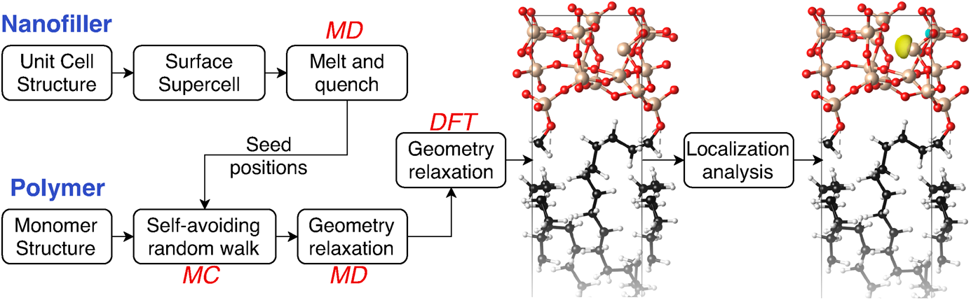
We, therefore, adopt a protocol that combines these approaches sequentially to generate amorphous structures of interfaces (Fig. 1). Classical MD simulations of the hard inorganic filler first generate an amorphous surface slab for that component by starting from a crystalline surface, heating to a molten state, and then rapidly cooling. Suitable surface sites of the filler then serve as seed positions for growing chains of polymers using a MC self-avoiding random walk simulation to fill the empty space within the unit cell (forming two back-to-back polymer–filler interfaces in a periodic box). This structure then forms the starting point for geometry relaxation, first using classical MD and then using DFT. (See Methods for computational details of each component.)

Figure 1: Overview of computational approach combining MD, MC simulations, and DFT calculations to generate ensembles of amorphous polymer–filler interface structures, compute electronic structure, and identify localized trap states relevant for determining dielectric breakdown strength.
Randomness in sampling ensembles of structures emerges naturally in both the MD quench of the inorganic filler component and the MC random walk for the polymer. In particular, changing the quench rate and dwell time in the liquid-state samples produces different filler structures. The self-avoiding random walk creates the backbone for the polymer chains, preserving bond lengths and bond angles, but has a free choice of torsion angles (except those that lead to intersections) drawn randomly at each monomer insertion. In addition, polymer chains attach to under-coordinated atoms on the filler surface, introducing a random choice of connection between the two subsystems, although remaining dangling bonds on the surface are hydrogen-terminated. In this initial study of polymer–filler interfaces, we choose intrinsic interfaces that do not contain any surface modifiers between the polymer and the fillers for simplicity. Furthermore, we specifically focus on silica–polyethylene interfaces, which have been extensively studied experimentally [Reference Lau, Vaughan, Chen, Hosier and Holt22, Reference Lau, Vaughan, Chen, Hosier, Ching and Quirke23, Reference Wang, Qiang, Xu, Chen and Vaughan24], and whose individual components exhibit relatively simple unit cell/monomer structures that have been investigated using first-principles and classical MD techniques previously.
Once we have generated an initial structure using the aforementioned protocol, and DFT calculations relax the structure to the nearest local minimum of the energy landscape and predict the corresponding energy eigenstates. From this set of energy eigenstates, we need to identify localized states that serve as traps for carrier transport. In these amorphous interface structures, we find that conventional strategies such as identifying states within the band gap of the bulk materials prove challenging because of the lack of clear band edges in the DOS profiles. Approaches using local DOS in atomic layers also do not easily extend beyond the crystalline cases studied previously [Reference Shi and Ramprasad14]. Consequently, we directly estimate localization of each state from the spatial extent of the corresponding electronic orbital, ψ(r). Specifically, we define the localization for each state indexed by i as follows:
 $${L_i} = {\left[ {\mathop {\min }\limits_{{r_0}} \int_\Omega {{{\left| {{\psi _i}\left( r \right)} \right|}^2}} {{\left( {r - {r_0}} \right)}^2}{\rm{d}}r} \right]^{ - 1}}\quad ,$$
which is the inverse second moment of the probability density of the state about its “center,” r 0. For a finite distribution, the minimization of the second moment over r 0 would converge r 0 to the expectation value of r (first moment), reducing the previous definition to the inverse variance. This does not strictly apply in periodic boundary conditions, but the definition in terms of minimization over r 0 still corresponds to the spatial spread around the center. In practice, we iteratively solve the minimization of the spread above, starting from an initial guess for r 0 taken to be the point in the unit cell with the highest value of |ψi(r)|2.
Figure 2 shows an example of calculated localization values and DOS for a specific silica–polyethylene structure from the ensembles analyzed in the following section. This structure exhibits four states that appear to be separated in energy from the bulk delocalized states of the material, as seen clearly in the DOS. However, the localization analysis reveals that an additional state close to the valence band edge is highly localized, but this is indistinguishable from the bulk states based on the conventional DOS analysis alone.

Figure 2: Estimated localization (blue cross) of each electronic state clearly separates localized trap-state candidates from delocalized states of the interface, and the DOS (green line) alone does not because these states may overlap in energy (e.g., the circled state).
The previous approach allows us to create ensembles of initial polymer–filler structures, optimize their geometries, and evaluate their electronic structure to identify localized trap states in each structure. To analyze the energy distribution of trap states from this ensemble, we additionally need to align the energy scales of each DFT calculation in the ensemble because of the undetermined energy offset in periodic calculations. We use semicore energy levels that are minimally affected by the local environment details beyond the long-range electrostatic potential to perform this alignment (specifically using the 2s states present in the silicon pseudopotentials for the silica component). After mutually aligning the energies of structures within the ensemble, we compute the ensemble-averaged electronic DOS, determine the average valence-band maximum (VBM) energy, and reference all results to this VBM energy. With this protocol for evaluating ensembles of amorphous structures, we now identify and compare trap states in crystalline and amorphous versions of bulk silica and polyethylene, with that of their amorphous interfaces.
Results and discussion
We first apply the aforementioned computational approach to amorphous silica before introducing polymer interfaces. In an ensemble of amorphous silica structures with 72 atoms each, only 40% exhibit localized trap states. Figure 3(a) shows the localization analysis and DOS of one such sample, which exhibits a shallow hole trap within 0.1 eV of the valence band edge and deeper electron traps of 1 eV from the conduction band edge. We find that hole traps in amorphous silica typically correspond to under-coordinated oxygen atoms bonded to a single silicon atom [Fig. 3(b)], whereas electron traps correspond to under-coordinated silicon atoms bonded to three oxygen atoms [Fig. 3(c)]. Furthermore, these two traps occur in pairs, resulting from a silicon–oxygen double bond of length 1.52 Å (shorter than the average Si–O bond length of 1.62 Å) that reduces the coordination of both atoms by one. By contrast, all states in crystalline quartz exhibit similar and low localization values, and the DOS of the valence band covers a narrower energy range than the amorphous silica ensemble. We also note that the probability of introducing localized defect states in this structure depends on the protocol for generating initial structures. Importantly, the approach of starting from crystalline quartz, melting, and quenching generates structures with lower defect probabilities than geometry optimization initiated from random atomic configurations. The quenching approach eliminates the bias from particular initial structures and generates an ensemble relatively insensitive to quench conditions once the temperature is large enough (see Methods for computational details).

Figure 3: (a) Localization of electronic states in one sample from an ensemble of bulk amorphous silica structures that exhibits localized trap states and DOS of that sample as well as the ensemble (top panel) compared with those for crystalline quartz (bottom panel). (b, c) Electronic orbitals corresponding to localized hole and electron trap states corresponding to under-coordinated oxygen and silicon atoms, respectively. Note that the narrow confidence interval in the DOS [red translucent band in top panel of (a)] indicates adequate sampling of amorphous silica structures in the ensemble.
In contrast to bulk amorphous silica, bare surfaces of amorphous silica exhibit a greater propensity to generate localized traps, both at the surface and in adjacent layers [Fig. 4(a) top panel], and predominantly at under-coordinated oxygen atoms [Fig. 4(b)]. Such defects may exist in oxygen-rich pure amorphous silica, but in proximity to a polymer matrix, under-coordinated oxygen atoms would most likely be terminated by hydrogen. Consequently, we investigate the impact of hydrogen-terminating of all under-coordinated oxygen atoms at the amorphous silica surface. This results in a substantial reduction in both the number and degree of localization of trap states [Fig. 4(a) bottom panel]. Specifically, the surface density of trap states in the ensemble reduces by almost a factor of two from approximately 8/nm2 to 5/nm2, whereas states spread out over the entire band gap to distributions within 1 eV from both band edges in addition to some mid-gap states approximately 3 eV from the valence band edge. The localization of the hole trap states near the valence band edge, in particular, reduces by more than a factor of two. These states remain on surface oxygen atoms even after they become –OH termini in the hydrogen-terminated surface [Fig. 4(c)].

Figure 4: (a) Bare silica surfaces exhibit high densities of strongly localized trap states (top panel), while hydrogen termination reduces the number and extent of localization of trap states, moving them closer to the valence band (bottom panel). Trap states emerge primarily from (b) singly coordinated oxygen atoms at the bare surface and (c) corresponding –OH termini at the hydrogenated surface. Note that the localization (blue cross) on the panel (a) and the corresponding atomic structure (b) and (c) is just one sample from an ensemble of structures explored in this study. Narrow confidence intervals in the ensemble DOS in (a) confirm adequate ensemble sampling.
The hydrogen-terminated amorphous silica surface serves as a starting point for analyzing silica–polyethylene interfaces in the nanocomposite material. In particular, the computational framework to generate such structures effectively replaces some of the hydrogen atoms on the under-coordinated surface oxygen atoms with the terminal carbon of the polymer. We perform DFT calculations and localization analysis on an ensemble of 150 interface structures. The top panel of Fig. 5(a) illustrates the localization and DOS of these interface structures. The characteristic number density of defects remains comparable with the H-terminated amorphous silica surface. This is primarily because the polymer region of the interface does not contribute trap states, similar to the amorphous bulk polymer shown in the bottom panel of Fig. 5(a). The localized trap states in the silica–polyethylene interface follow two characteristic motifs. Figure 5(b) shows trap states at the surface oxygen atoms connecting the silica to the polymer, which are closely related to the –OH termini of the H-terminated amorphous silica surface shown in Fig. 4(c). Figure 5(c) illustrates traps resulting from under-coordinated silicon atoms, bonded to three oxygen atoms instead of four, which generates a highly localized trap state near the valence band.

Figure 5: (a) Localization (blue cross) and DOS (green dashed line) for an instance of the silica–polyethylene interface (top panel) and bulk amorphous polyethylene (bottom panel) with the ensemble-averaged DOS (black bold line). Electronic orbitals for localized trap states corresponding to (b) bridging oxygen atoms at the silica–polymer interface and (c) under-coordinated silicon atoms. Bulk polyethylene does not exhibit any significantly localized trap states. As in Figs. 3 and 4, the narrow confidence interval in the DOS [red translucent band in (a)] indicates adequate sampling in the ensemble of structures.
Interestingly, we find no strongly localized trap states in the polymer region, despite capturing disordered structures of relatively long (53 carbon) polymer chains. The protocol for generating the initial structures enables disorder but does not introduce broken C–C or C–H bonds on account of the high energetic cost of doing so. Unlike the amorphous silica, distortions of the polymer do not disrupt the bonding sufficiently to create localized states within it. Consequently, as discussed earlier, bulk amorphous polyethylene (without silica) also does not exhibit any localized states [bottom panel of Fig. 5(a)].
Finally, we examine the ensemble-averaged local DOS of the silica–polyethylene interface to simultaneously visualize the spatial locations and energy distributions of the trap states (Fig. 6). The silica valence band edge is 1 eV less than that of the polymer, such that the bulk states of silica cannot serve to inhibit transport in the polymer. However, the interface states localized to the silica surface region discussed earlier generate a multimodal distribution of shallow and deep traps within the polymer band gap. This combination of shallow and deep traps is critical in explanations of measured space charge profiles in nanodielectrics. Specifically, this leads to a significant reduction in mobility with time as carriers initially injected into shallow traps migrate into successively deeper traps [Reference Huang, Wu, Bell, Oakes, Ratcliff, Lanzillo, Breneman, Benicewicz and Schadler7].

Figure 6: Ensemble-averaged local DOS of the silica–polyethylene interface, illustrating the spatial and energy distribution of the localized trap states. The top panel shows the energy distribution (per unit interfacial area) of the localized states alone, exhibiting a multimodal distribution of shallow and deep hole traps critical for inhibiting breakdown [Reference Huang, Wu, Bell, Oakes, Ratcliff, Lanzillo, Breneman, Benicewicz and Schadler7].
Conclusions
The computational approach presented here to automatically generate structures of amorphous polymer–filler interfaces makes it now possible to systematically calculate the electronic structure of ensembles of such amorphous structures. Furthermore, localization analysis of electronic states based on the second moment of the orbital density facilitates unambiguous identification of localized trap states, even when they overlap in energy with the band edge states. Application of this approach to polyethylene–silica interfaces finds that trap states emerge primarily near the surface of amorphous silica, with under-coordinated silicon atoms and bridging oxygen atoms at the interface, leading to the most localized trap states, whereas the amorphous polyethylene does not contribute any substantially localized states despite the disorder.
This work lays the foundation for future systematic analyses of trap distributions in realistic amorphous nanodielectric interfaces with first-principles techniques. Although polyethylene did not contribute trap states, amorphous structures of other dielectric polymers including polymethyl-methacrylate (PMMA), polystyrene (PS), and polyvinylidene fluoride (PVDF) could exhibit localized states because of the larger fluctuations in the electrostatic potential created by disorder of polar groups. Analogously, replacing silica with more polar nanofillers such as alumina and barium titanate could also reveal a larger impact on the carrier energy landscape within the polymer.
Future work could also explore the impact of realistic amorphous configurations of surface functionalizations on the nanofillers, which are often introduced experimentally to improve wettability and dispersion of nanoparticles in the polymer matrix [Reference Huang, Wu, Bell, Oakes, Ratcliff, Lanzillo, Breneman, Benicewicz and Schadler7]. Finally, recent methodological advances in first-principles calculations of solid–liquid and electrochemical interfaces, including accurate continuum solvation models [Reference Sundararaman and Goddard25, Reference Sundararaman, Schwarz, Letchworth-Weaver and Arias26] and prediction of electronic level alignment methods [Reference Sundararaman and Ping27, Reference Ping, Sundararaman and Goddard28] that automatically deal with changing local charge states, could facilitate similar advances in ab initio predictive capability for the structure and energetics of amorphous polymer interfaces.
Methods
Silica structure generation
The starting point for all silica structures is a 2 × 2 × 2 supercell of quartz with 72 atoms covering a unit cell of approximate dimensions 10 × 10 × 20 Å. For surface structures, we expand the (0001) direction to 60 Å, creating two surfaces approximately 40 Å apart. Classical MD simulations using open-source LAMMPS software [Reference Plimpton29] and pair potential force fields developed for silicate glasses [Reference Sundararaman, Huang, Ispas and Kob30, Reference Sundararaman, Ching and Huang31, Reference Sundararaman, Huang, Ispas and Kob32] equilibrate these structures at 300 K, heat to 2000 K, equilibrate at that temperature, cool back to 300 K, and then equilibrate once again. Each of these five stages lasts for 8–32 picoseconds (selected at random), with a time step of 1.6 femtoseconds. To test the sensitivity of our results to this protocol, we also performed calculations for bulk amorphous silica starting from structures annealed for longer times and at 4000 K and found no significant differences in the resulting distribution of localized trap states. Further processing for interface structure generation is carried out using selected silica surfaces with at least one under-coordinated oxygen atom to use as a site for attaching the polymer chains.
Polyethylene structure generation
A self-avoiding random walk algorithm [Reference Kremer and Grest21], implemented in an in-house C++ code (available upon request), generates polymer chains starting from graft coordinates based on the under-coordinated oxygen atoms for the interface cases and selected at random for the bulk polymer cases. Given a target mass density and boundary conditions (periodic in x and y, confined in z), this code initiates carbon chains at each graft site and grows them with specified bond lengths and angles (set to 1.54 Å and 109.5° for polyethylene) and uniformly random torsion angles that avoid intersections with any chain within a specified distance threshold. From this initial random structure, MD simulations in LAMMPS using a unified-atom force-field model of polyethylene [Reference Hossain, Tschopp, Ward, Bouvard, Wang and Horstemeyer33] relax the structure to achieve realistic geometries of the backbones, with the grafted locations held stationary and with repulsive walls on the z boundaries to prevent intersection with the inorganic filler location. Finally, the addition of hydrogen atoms at tetrahedral locations relative to the backbone using Avogadro [Reference Hanwell, Curtis, Lonie, Vandermeersch, Zurek and Hutchison34] creates a full atomistic model of polyethylene.
Interface structure generation
The structures for silica and polyethylene generated earlier are spatially compatible because of the choice of starting position and boundary conditions of the polymer growth. The only modifications necessary are the removal of the terminal hydrogen on the polymer to facilitate its bonding with the surface, and optionally, hydrogen termination of any dangling bonds on the surface. The integrated structure in a unit cell of an approximate dimension 10 × 10 × 60 Å serves as the starting point for geometry optimization and trap-state evaluation using DFT.
Density functional theory
The interface configurations generated earlier, each with approximately 300 atoms and 1000 valence electrons, serve as starting points for full geometry optimization using electronic DFT using our open-source DFT software, JDFTx [Reference Sundararaman, Letchworth-Weaver, Schwarz, Gunceler, Ozhabes and Arias35]. (The same methodology applies to the corresponding bulk structures and surfaces.) These calculations use ultrasoft psuedopotentials [Reference Garrity, Bennett, Rabe and Vanderbilt36], kinetic energy cutoffs of 20 and 100 Hartrees, respectively, for the plane-wave expansion of the wavefunctions and electron density, the Perdew–Burke–Ernzerhof (PBE) generalized gradient approximation to the exchange-correlation functional [Reference Perdew, Burke and Ernzerhof37], Γ-point sampling of the Brillouin zone, and the DFT + D2 pair-potential correction for long-range dispersion interactions [Reference Grimme38]. Direct variational minimization converges the electronic wavefunctions [Reference Arias, Payne and Joannopoulos39] to an energy accuracy threshold of 10−7 Hartrees, with geometry optimization terminated on a force threshold of 10−4 Hartrees/Bohr, and a final electronic structure evaluation with an increased convergence threshold of 10−9 Hartrees and 100 extra bands generate the final electronic states (including empty conduction band states) analyzed previously. For each amorphous material or interface system, we mutually align the energies of calculations within the ensemble using semicore-level energies and then reference them to the average valence band maximum (VBM) energy of the ensemble. DOS calculations use the tetrahedron method [Reference Lehmann and Taut40], and trap-state visualization uses phase-corrected (real-valued) wave functions output by JDFTx for visualization along with the atomic structure in VESTA [Reference Momma and Izumi41].
Acknowledgments
This material is based on the work supported by the National Science Foundation under Grant No. 1729452. All calculations were carried out at the Center for Computational Innovations at Rensselaer Polytechnic Institute.


 Open access