


1. Introduction
Microfluidic applications for sorting and separation of particles and biological cells have seen tremendous growth in recent years (Stone & Kim Reference Stone and Kim2001; Gossett et al. Reference Gossett, Weaver, Mach, Hur, Tse, Lee, Amini and Di Carlo2010; Karimi, Yazdi & Ardekani Reference Karimi, Yazdi and Ardekani2013). Passive techniques utilized for this purpose generally exploit the hydrodynamic forces that preferentially accumulate or ‘focus’ particles in specific regions. The hydrodynamic mechanism underlying such focusing is a migration of particles across the streamlines of the background flow. Such cross-stream migration may arise because of the effect of inertia, particle deformability, presence of a wall, shear gradient and streamline curvature, among others (Di Carlo Reference Di Carlo2009; Karimi et al. Reference Karimi, Yazdi and Ardekani2013; Zhou & Papautsky Reference Zhou and Papautsky2013; Martel & Toner Reference Martel and Toner2014). Focusing by the inertial effects, commonly termed as inertial focusing, was first reported for rigid particles in pipe flow by Segre & Silberberg (Reference Segre and Silberberg1961, Reference Segre and Silberberg1962), who observed that particles accumulate in an equilibrium annular region between the pipe centre and the wall. Since then the phenomenon, also known as the tubular pinch effect, has been extensively studied using theoretical, computational and experimental approaches for flow in pipes as well as in two-dimensional (2-D) (planar) confined pressure-driven flows (e.g. Repetti & Leonard Reference Repetti and Leonard1964; Jeffrey & Pearson Reference Jeffrey and Pearson1965; Karnis, Goldsmith & Mason Reference Karnis, Goldsmith and Mason1966; Cox & Brenner Reference Cox and Brenner1968; Ho & Leal Reference Ho and Leal1974; Schonberg & Hinch Reference Schonberg and Hinch1989; Asmolov Reference Asmolov1999; Matas, Morris & Guazzelli Reference Matas, Morris and Guazzelli2004, Reference Matas, Morris and Guazzelli2009; Yu, Phan-Thien & Tanner Reference Yu, Phan-Thien and Tanner2004; Yang et al. Reference Yang, Wang, Joseph, Hu, Pan and Glowinski2005; Shao, Yu & Sun Reference Shao, Yu and Sun2008). These studies generally have shown that the focusing annulus moves closer to the wall with increasing Reynolds number (defined based on vessel dimension). For tubes at higher Reynolds numbers, a second focusing annulus closer to the centre is also reported (Matas et al. Reference Matas, Morris and Guazzelli2004; Morita, Itano & Sugihara-Seki Reference Morita, Itano and Sugihara-Seki2017). For neutrally buoyant rigid particles suspended in a Newtonian fluid, the equilibrium is attained primarily under the influence of the shear gradient of the background flow, wall repulsion effect, particle rotation and Saffman lift force (Oliver Reference Oliver1962; Saffman Reference Saffman1965). The term inertial lift is often used to represent the net hydrodynamic force generated from these mechanisms. The Saffman lift force is small for microfluidic applications (Amini, Lee & Di Carlo Reference Amini, Lee and Di Carlo2014).
Of specific interest to microfluidic applications is the inertial focusing in microchannels of square or rectangular cross-section. For such geometry, depending on channel cross-section (viz. square or rectangular), the channel Reynolds number (hereafter denoted as  $Re_{C}$), particle Reynolds number and particle-to-channel size ratio, different regions of focusing have been reported which are significantly different from the axisymmetric focusing in pipes. For relatively smaller $Re_{C}$ within the inertial regime, Choi, Seo & Lee (Reference Choi, Seo and Lee2011) experimentally observed that rigid spherical particles focused in a ring. At higher $Re_{C}$, the ring breaks and four equilibrium positions appear that are located at the centres of channel faces (Chun & Ladd Reference Chun and Ladd2006; Di Carlo et al. Reference Di Carlo, Irimia, Tompkin and Toner2007; Bhagat, Kuntaegowdanahalli & Papautsky Reference Bhagat, Kuntaegowdanahalli and Papautsky2008a, Di Carlo et al. Reference Di Carlo, Edd, Humphry, Stone and Toner2009; Humphry et al. Reference Humphry, Kulkarni, Weitz, Morris and Stone2010; Miura, Itano & Sugihara-Seki Reference Miura, Itano and Sugihara-Seki2014; Nakagawa et al. Reference Nakagawa, Yabu, Otomo, Kase, Makino, Itano and Sugihara-Seki2015; Kazerooni et al. Reference Kazerooni, Fornari, Hussong and Brandt2017). Additional equilibrium positions appearing near the channel corners and accumulation at an inner region at higher $Re_{C}$ are also reported (Chun & Ladd Reference Chun and Ladd2006; Di Carlo et al. Reference Di Carlo, Edd, Humphry, Stone and Toner2009; Miura et al. Reference Miura, Itano and Sugihara-Seki2014; Nakagawa et al. Reference Nakagawa, Yabu, Otomo, Kase, Makino, Itano and Sugihara-Seki2015; Kazerooni et al. Reference Kazerooni, Fornari, Hussong and Brandt2017). For channels with rectangular cross-sections of high aspect ratio, the shear gradient effect along the longer side may weaken, resulting in primarily two equilibrium positions at the centres of the longer sides of the channel (Bhagat et al. Reference Bhagat, Kuntaegowdanahalli and Papautsky2008a, Bhagat, Kuntaegowdanahalli & Papautsky Reference Bhagat, Kuntaegowdanahalli and Papautsky2008b, Reference Bhagat, Kuntaegowdanahalli and Papautsky2009; Russom et al. Reference Russom, Gupta, Nagrath, Di Carlo, Edd and Toner2009; Ciftlik, Ettori & Gijs Reference Ciftlik, Ettori and Gijs2013; Martel & Toner Reference Martel and Toner2014; Liu et al. Reference Liu, Hu, Jiang and Sun2015; Hood et al. Reference Hood, Kahkeshani, Di Carlo and Roper2016). An additional equilibrium near the shorter face at higher $Re_{C}$ is also reported (Liu et al. Reference Liu, Hu, Jiang and Sun2015).
In recent years, microchannels with curved geometry, such as spiral and serpentine channels, have shown greater promise in terms of more effective particle focusing compared with their rectilinear counterparts (Liu et al. Reference Liu, Petchakup, Tay, Li and Hou2019). In curved channels at finite inertia, a secondary flow appears in the form of two counter-rotating vortices, often termed Dean's vortices (Dean Reference Dean1928), which exert a drag on particles. Cross-stream migration and the equilibrium position in such flows are then determined by the combined effects of Dean's drag and the inertial lift (Di Carlo et al. Reference Di Carlo, Irimia, Tompkin and Toner2007; Di Carlo Reference Di Carlo2009; Gossett & Di Carlo Reference Gossett and Di Carlo2009; Russom et al. Reference Russom, Gupta, Nagrath, Di Carlo, Edd and Toner2009; Martel & Toner Reference Martel and Toner2012, Reference Martel and Toner2013, Reference Martel and Toner2014; Karimi et al. Reference Karimi, Yazdi and Ardekani2013; Warkiani et al. Reference Warkiani, Khoo, Wu, Tay, Bhagat, Han and Lim2016; Harding, Stokes & Bertozzi Reference Harding, Stokes and Bertozzi2019). Additionally, the shear gradient effect is also altered as the streamwise velocity distribution becomes skewed toward the exterior face (i.e. side with the largest radius of curvature) of the channel (Vriend Reference Vriend1981; Siggers & Waters Reference Siggers and Waters2005). The secondary flow in curved channels provides several advantages over rectilinear channels. In particular, equilibrium positions along the top and bottom walls (i.e. parallel to the radial direction), and near the exterior face can be eliminated, and single-point focusing can be achieved. When the inertial lift dominates (e.g. for larger particle-to-channel size ratio), rigid particles are shown to focus near the centre of the interior face. In contrast, as the Dean drag dominates over the inertial lift (e.g. for smaller particle size), equilibria appear along the top and bottom walls and progressively move away from the interior wall (Di Carlo Reference Di Carlo2009; Martel & Toner Reference Martel and Toner2013; Harding et al. Reference Harding, Stokes and Bertozzi2019). Very small particles can be entrapped within the Dean vortices (Harding et al. Reference Harding, Stokes and Bertozzi2019).
In many applications, the particles of interest, such as liquid drops and biological cells, are deformable in nature. While the cross-streamline migration and focusing of rigid particles are generally observed in the presence of inertia, for deformable particles they can occur even in the absence of inertia, and are referred to as non-inertial migration and focusing. This has been studied extensively in rectilinear vessels for liquid drops, blood cells and biomimetic deformable particles such as capsules and vesicles, which are liquid drops enclosed by elastic and lipid membranes, respectively (Chan & Leal Reference Chan and Leal1979, Reference Chan and Leal1981; Helmy & Barthes-Biesel Reference Helmy and Barthes-Biesel1982; Shapira & Haber Reference Shapira and Haber1990; Uijttewaal & Nijhof Reference Uijttewaal and Nijhof1995; Magnaudet, Takagi & Legendre Reference Magnaudet, Takagi and Legendre2003; Griggs, Zinchenko & Davis Reference Griggs, Zinchenko and Davis2007; Coupier et al. Reference Coupier, Kaoui, Podgorski and Misbah2008; Doddi & Bagchi Reference Doddi and Bagchi2008; Kaoui et al. Reference Kaoui, Ristow, Cantat, Misbah and Zimmermann2008; Danker, Vlahovska & Misbah Reference Danker, Vlahovska and Misbah2009; Kumar & Graham Reference Kumar and Graham2012; Farutin & Misbah Reference Farutin and Misbah2013; Grandchamp et al. Reference Grandchamp, Coupier, Srivastav, Minetti and Podgorski2013; Nix et al. Reference Nix, Imai, Matsunaga, Yamaguchi and Ishikawa2014; Sing, Li & Sarkar Reference Sing, Li and Sarkar2014; Nix, Imai & Ishikawa Reference Nix, Imai and Ishikawa2016; Losserand, Coupier & Podgorski Reference Losserand, Coupier and Podgorski2019). The hydrodynamic mechanism underlying such non-inertial migration can be attributed to an asymmetry in shape deformation caused by the shear gradient of the flow or the presence of a wall. The influence of deformation generally causes a migration toward a region of low shear, while the wall interaction causes a migration away from the wall. As such, in confined flows in the absence of inertia, deformable particles generally settle at the centreline of a rectilinear channel or tube. The migration rate increases with increasing deformability, thereby allowing deformability-based particle focusing and sorting in the non-inertial regime (Geislinger et al. Reference Geislinger, Eggart, Braunmüller, Schmid and Franke2012; Henríquez Rivera, Zhang & Graham Reference Henríquez Rivera, Zhang and Graham2016).
Inertial migration of deformable particles has also been investigated in rectilinear vessels or 2-D planar flows for liquid drops (e.g. Mortazavi & Tryggvason Reference Mortazavi and Tryggvason2000; Magnaudet et al. Reference Magnaudet, Takagi and Legendre2003), capsules (Kilimnik, Mao & Alexeev Reference Kilimnik, Mao and Alexeev2011; Shin & Sung Reference Shin and Sung2011; Krüger, Kaoui & Harting Reference Krüger, Kaoui and Harting2014; Raffiee, Dabiri & Ardekani Reference Raffiee, Dabiri and Ardekani2017; Schaaf & Stark Reference Schaaf and Stark2017) and elastic particles (Alghalibi, Rosti & Brandt Reference Alghalibi, Rosti and Brandt2019). In this case, the migration and equilibrium positions are determined by the combined influence of the inertial lift and deformation. While the former tends to shift the equilibrium away from the centreline, the latter causes it to shift in the opposite way. Generally, studies on capsule motion showed that, for fixed  $Re_{C}$, the equilibrium position shifts away from the centreline with decreasing deformability and capsule size. However, it remains almost independent of $Re_{C}$ for a given geometry. Moreover, the equilibria for capsules in square channels appear mostly along the diagonals (Raffiee et al. Reference Raffiee, Dabiri and Ardekani2017; Schaaf & Stark Reference Schaaf and Stark2017). Despite a relatively small number of studies on the inertial migration of capsules, it is apparent that there are interesting differences in their focusing behaviour in comparison with rigid particles, and in channels of square or rectangular cross-section in comparison with tubes with circular cross-sections.
There have been even fewer studies on the inertial and non-inertial focusing of deformable particles in curved microchannels. This specific topic deserves attention since deformation is often significant for biological cells and biomimetic particles, and the curved geometry can be utilized for focusing such particles under both inertial and non-inertial conditions. However, the fundamental difference in the background flow that occurs in a curved vessel in the inertial and non-inertial regimes must be noted. Unlike in the inertial regime where secondary flow characterized by Dean's vortices appears, no such secondary flow exists in the non-inertial regime. Instead, the streamwise flow itself becomes asymmetric about the vessel centreline and skewed toward the interior side of the vessel (Dean Reference Dean1928; Vriend Reference Vriend1981; Chadwick Reference Chadwick1985; Wang & Bassingthwaighte Reference Wang and Bassingthwaighte2003; Siggers & Waters Reference Siggers and Waters2005). In contrast, in the inertial regime the velocity profile becomes skewed toward the exterior side. This change in the velocity profile is expected to differently affect the focusing and migration behaviour in the inertial and non-inertial regimes, in addition to the role played by the secondary flow. Additionally, the curvature of the flow streamlines induces a migration of deformable particles toward the regions of higher streamline curvature. This streamline curvature effect is absent for rigid particles without inertia (Shafer, Laiken & Zimm Reference Shafer, Laiken and Zimm1974; Goh, Phan Thien & Atkinson Reference Goh, Phan Thien and Atkinson1984). Chan & Leal (Reference Chan and Leal1979) predicted that, in the non-inertial regime, the streamline curvature effect caused a liquid drop to migrate toward the inner cylinder in a 2-D rotating Couette flow. Ghigliotti et al. (Reference Ghigliotti, Rahimian, Biros and Misbah2011) predicted that deformable vesicles in a 2-D rotating flow migrate toward the region of high streamline curvature in an unbounded flow and settle at an intermediate radial location in flows bounded by two walls. Considering 3-D curved vessels, such as curved microchannels, the focusing and migration depend on the complex interplay of all the aforementioned mechanisms, namely, inertia, altered velocity skewness, deformation, curvature and secondary flow. In the inertial regime in 3-D flows, Ye et al. (Reference Ye, Phan-Thien, Lim and Li2017) numerically studied the flow of red blood cells in curved tubes and the effect of tube geometry on cell deformation. Ye et al. (Reference Ye, Phan-thien, Khoo and Li2018) further studied the modification of the secondary flow by red blood cells in U-shaped tubes. Despite these recent works, there have been very few studies systematically exploring the focusing of deformable particles in 3-D flows in curved vessels.
To bridge this knowledge gap, Ebrahimi, Balogh & Bagchi (Reference Ebrahimi, Balogh and Bagchi2021) recently considered a numerical study of the flow of deformable capsules in toroidal vessels of circular cross-section. They predicted that, in the non-inertial regime, capsules settle at a radial location between the inner side (highest curvature side) of the tube and the location of the maximum streamwise velocity. Furthermore, the equilibrium location is independent of capsule deformability, and it moves closer to the inner side with increasing vessel curvature. In the inertial regime, the equilibrium position gradually moves toward the outer side (lower curvature side) of the tube depending on fluid inertia and deformability. At higher fluid inertia, when the secondary flow becomes stronger, capsules settle near the centres of the Dean vortices.
In the present study, we extend the work of Ebrahimi et al. (Reference Ebrahimi, Balogh and Bagchi2021) to consider focusing of deformable capsules in curved microchannels of square and rectangular cross-sections. The objective is to predict the cross-stream migration and equilibrium position of capsules under the combined influence of deformability, channel curvature, cross-sectional geometry and a broad range of inertia covering both the inertial (secondary flow) and non-inertial regimes. Unlike in a vessel of circular cross-section, the aspect ratio of microchannels, which affects the flow dynamics in both inertial and non-inertial regimes, is also considered. No study has systematically addressed the cross-stream migration and capsule equilibrium in curved microchannels under such a wide range of conditions.
2. Problem set-up and numerical methodology
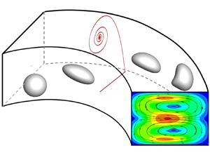
We consider a closed-loop curved microchannel of square or rectangular cross-section, and a constant centreline radius of curvature as shown in figure 1. The channel is centred at the origin of the cylindrical polar coordinate system denoted by  $(\tilde{R},\varTheta ,\tilde{Z})$, with the $\tilde{Z} = 0$ plane being the symmetry (middle) plane. The dimensional parameters are denoted by ${\sim} $. The channel width, which is the dimension in the radial direction, is $2\tilde{W}$, and the height, which is the dimension along the $\tilde{Z}$ axis, is $2\tilde{H}$. The radius of curvature of the channel centreline is ${\tilde{R}_C}$ and ${\tilde{R}_C} \pm \tilde{W}$ are the radii of the exterior and interior faces of the channel.

Figure 1. Schematic of a curved microchannel of rectangular cross-section. All lengths are shown in dimensionless form scaled by capsule radius. Channel centreline (radius of curvature  ${R_C}$) is indicated by a dash-dot curve.
The fluid inside the channel is assumed to be incompressible and Newtonian, and follows the continuity and the full Navier–Stokes equations including the inertial terms
 \begin{gather}\boldsymbol{\nabla }\boldsymbol{\cdot }\tilde{\boldsymbol{u}} = 0,\end{gather}
 \begin{gather}\rho \frac{{\textrm{D}\tilde{\boldsymbol{u}}}}{{\textrm{D}\tilde{t}}} ={-} \boldsymbol{\nabla }\tilde{p} + \mu {\nabla ^2}\tilde{\boldsymbol{u}},\end{gather}
where  $\tilde{\boldsymbol{u}}$ is the fluid velocity, $\tilde{p}$ pressure, $\rho $ density and $\mu $ viscosity. Here, variables in the dimensional form are denoted with ${\sim} $. The fluid is driven by a steady streamwise pressure gradient given by
 \begin{equation}\left( {\frac{1}{{{{\tilde{R}}_C}}}} \right)\frac{{\textrm{d}\tilde{P}}}{{\textrm{d}\varTheta }} ={-} \frac{{\mu {{\rm \pi} ^3}{{\tilde{U}}_0}}}{{16{{\tilde{W}}^2}\xi }},\end{equation}
where
 \begin{equation}\xi = \mathop \sum \limits_{n = 1,3,5, \ldots } \frac{{{{( - 1)}^{(n - 1)/2}}}}{{{n^3}}}\left\{ {1 - \textrm{sech}\left( {\frac{{n{\rm \pi} \tilde{W}}}{{2\tilde{H}}}} \right)} \right\},\end{equation}
and  ${\tilde{U}_0}$ is the centreline velocity that would occur for a unidirectional flow in a rectilinear channel having the same width and height as of the curved channel (White Reference White1991).
The flow of a capsule of an undeformed spherical shape of radius  ${a_0}$ is considered. The capsule is modelled as a liquid drop surrounded by a 2-D hyperelastic membrane. The fluid inside the capsule is assumed to have the same viscosity and density as the outside fluid. Because of the elastic nature of the membrane and the internal fluid, the capsule deforms under the motion of the suspending fluid. The capsule membrane is assumed to undergo shearing deformation, area dilation and bending. The shearing deformation and area dilation are modelled using the strain energy function developed by Skalak et al. (Reference Skalak, Tozeren, Zarda and Chien1973),
 \begin{equation}{W_S} = \frac{{{G_S}}}{4}[(I_1^2 + 2{I_1} - 2{I_2}) + CI_2^2],\end{equation}
where  ${G_S}$ is the shear modulus of elasticity of the membrane, C is a dimensionless parameter that controls the amount of membrane area dilation, ${I_1} = \varepsilon _1^2 + \varepsilon _2^2 - 2$ and ${I_2} = \varepsilon _1^2\varepsilon _2^2 - 1$ are the strain invariants of the Green strain tensor and ${\varepsilon _1}$and ${\varepsilon _2}$ are the principal stretch ratios. The principal in-plane elastic tensions in the membrane are given by
 \begin{equation}{\tau _1} = \frac{1}{{{\varepsilon _2}}}\frac{{\partial {W_S}}}{{\partial {\varepsilon _1}}}\quad \textrm{and}\quad {\tau _2} = \frac{1}{{{\varepsilon _1}}}\frac{{\partial {W_S}}}{{\partial {\varepsilon _2}}}.\end{equation}
The bending resistance is modelled by a force density following Zong-can & Helfrich (Reference Zong-Can and Helfrich1989) as
 \begin{equation}{\boldsymbol{f}_b} = {E_b}[(2{k_m} + {c_0})(2k_m^2 - 2{k_g} - {c_0}{k_m}) + 2{\varDelta _{LB}}{k_m}]\boldsymbol{n},\end{equation}
where  ${E_b}$ is the bending modulus, ${k_m}$, ${k_g}$ and ${c_0}$ respectively are the mean, Gaussian and spontaneous curvatures of the membrane, ${\varDelta _{LB}}$ is the Laplace–Beltrami operator and $\boldsymbol{n}$ is the unit vector normal to the capsule surface.
The computational domain is a cuboid encompassing the curved microchannel. A rectangular mesh of uniform spacing is used to discretize the whole domain. A sharp-interface immersed boundary method, namely, the ghost-node method, is used to represent the microchannel geometry, and to impose the no-slip condition at the channel walls. A staggered arrangement of the flow variables is considered in combination with a projection-based method with a second-order finite-volume-based spatial differencing and a second-order time differencing. Further details about the ghost-node method and the flow solver are provided in Balogh & Bagchi (Reference Balogh and Bagchi2017).
The capsule surface is discretized using triangular elements. A finite-element method is used to compute the elastic forces due to shearing and area dilation, while the force due to bending resistance is directly obtained from (2.7). The coupling between the capsule deformation and the fluid motion is obtained using a continuous-forcing immersed boundary method. In this approach, the net membrane force from shearing deformation, area dilation and bending is included in the Navier–Stokes equations as a body force that is finite at the instantaneous membrane location, and zero elsewhere. Once the fluid velocity is obtained at any time by solving the Navier–Stokes and continuity equations, the velocity of the capsule membrane points is obtained by interpolating the surrounding fluid velocity, followed by their advection to obtain a new shape and location of the capsule. Further details about the finite-element method and the continuous-forcing immersed boundary method can be found in Doddi & Bagchi (Reference Doddi and Bagchi2008) and Yazdani & Bagchi (Reference Yazdani and Bagchi2012, Reference Yazdani and Bagchi2013).
The parameters of the problem are now discussed. The hydraulic diameter and radius,  ${\tilde{D}_h}$ and ${\tilde{R}_h}$, of the channel are defined as ${\tilde{D}_h} = 2{\tilde{R}_h} = 4\tilde{H}\tilde{W}/(\tilde{H} + \tilde{W})$. Lengths are made dimensionless by the undeformed capsule radius ${a_0}$, velocities by the centreline velocity in a rectilinear channel ${\tilde{U}_0}$ and time by ${a_0}/{\tilde{U}_0}$. These are the relevant scales since the flow around the capsule needs to be resolved, and the shear rate is not constant but varies over the channel cross-section. We solve the Navier–Stokes equations in dimensionless form. A straightforward choice for making the equations dimensionless is to use these scales. In dimensionless form, the radial and vertical coordinates are denoted as $R,Z$, respectively; the geometric parameters as ${R_C}(\textrm{radius}\ \textrm{of}\ \textrm{curvature}\ \textrm{of}\ \textrm{channel}\ \textrm{centreline}),W$ (channel half-width), H (channel half-height), ${D_h}$ (hydraulic diameter) and ${R_h}$ (hydraulic radius). The flow variables in the dimensionless form are denoted without the symbol ${\sim} $.
We further introduce a dimensionless radial distance defined as
 \begin{equation}R^{\prime} = (R - {R_c})/W,\end{equation}
such that  $R^{\prime} ={-} 1,\; 0,\; 1$ represent, respectively, the interior face, the channel centreline and the exterior face.
Major dimensionless parameters are as follows:
Capillary number  $Ca = \mu {\tilde{U}_0}/{G_S}$ which represents the ratio of the viscous force to the membrane elastic force;
capsule Reynolds number $Re_{a} = \rho {a_0}{\tilde{U}_0}/\mu $;
channel Reynolds number
$Re_{C} = \rho {\tilde{D}_h}{\tilde{U}_0}/\mu = {D_h}Re_{a}$;channel centreline curvature ratio
$\kappa = W/{R_c}$; andDean number
$De = Re_{C}\sqrt \kappa $.


Note that the above definition of  $Re_{a}$ directly arises from non-dimensionalization of the Navier–Stokes equations. The range of $Ca$ considered is from 0.02 to 10 representing nearly rigid to highly deformable capsules, $Re_{C}$ from 0.06 to 320 covering non-inertial to inertial regimes, and $\kappa $ in the range of ~0.2 to 0.9 representing microchannels of high curvature. The radius of curvature is varied from ${R_C} = 4$ to 15, and ${D_h}$ from 6 to 18. Depending on the specific choice of geometric parameters, the Dean number ranges from ∼0.03 to 286. The non-inertial regime is considered by fixing the capsule Reynolds number $Re_{a} = 0.01$; for varying ${R_C},\; W$, and H, this results in $Re_{C}$ and $De$ both less than 0.1, so that the inertial effects can be assumed to be negligible. In contrast, the inertial regime is taken as $Re_{a}\gtrsim 0.1$; this results in $Re_{C}$ generally ${O}(1)$ and above. It may be noted that above a critical $De$, more than two Dean vortices appear and the flow becomes unstable. However, the highest De considered here is below this limit and it yields a steady flow with two stable vortices. The dimensionless bending modulus $E_b^\ast{=} {E_b}/{a^2}{G_s}$ is kept constant at 0.01, which is close to that of a red blood cell for which dimensional ${E_b}\sim {10^{ - 19}}\ \textrm{J}$, ${a_0}\sim 3\ {\rm \mu}\textrm{m}$ and ${G_S}\sim 3\ \textrm{N}\ {\textrm{m}^{-2}}$.
Extensive validation of the methodology has been done in our previous studies, and therefore, is not considered here. Specifically, the ghost-node method to model deformable cellular flows in complex geometry is validated in Balogh & Bagchi (Reference Balogh and Bagchi2017), the finite-element method for capsule deformation in Doddi & Bagchi (Reference Doddi and Bagchi2008) and capsule motion through a torus of a circular cross-section at finite inertia in Ebrahimi et al. (Reference Ebrahimi, Balogh and Bagchi2021). The suitable choice of computational mesh resolution is also discussed in these prior studies. Based on this, the flow domain is discretized with a dimensionless mesh size  $2{\rm \pi} /120$, the capsule surface is discretized using 20482 triangular elements, and a timestep of ${10^{ - 3}}$ is taken. The actual number of mesh points used for the flow domain varies depending on the dimensions of the microchannel; examples are $6.3 \times {10^6}$ points for ${R_C} = 5,\;W = H = 4$, and $57.4 \times {10^6}$ for ${R_C} = 10,\;W = H = 9$. The number of Eulerian mesh points per capsule diameter is approximately 38. The number of Eulerian points across the channel width and height depends on their values; e.g. approximately 76 and 344 points across the width for $W = 2$ and 9, respectively. Additional validation for the flow in curved microchannels relevant to the present study is given in the Results section.
Non-inertial focusing of capsules in curved microchannels of square cross-sections is presented next in § 3.1, followed by rectangular cross-sections in § 3.2. Inertial focusing is presented in § 3.3.
3. Results
3.1. Non-inertial focusing in curved channels of square cross-sections
Non-inertial migration of capsules in curved channels with square cross-sections is considered first. Figure 2(a) presents the numerically predicted streamwise fluid velocity component, denoted by  ${U_S}$ in dimensionless form, without a capsule over the cross-section of a channel for a selected geometry. As seen, the velocity distribution in the cross-sectional plane is asymmetric with respect to the channel centreline, and shifted toward the interior face, unlike in a rectilinear channel where the distribution would be symmetric. The secondary flow is negligible in this limit, and hence the Dean vortices are not observed. The skewed velocity profile is a result of the constant streamwise pressure gradient $(1/{\tilde{R}_C})\textrm{d}\tilde{P}/\textrm{d}\varTheta $ used to drive the flow which causes a higher velocity of the fluid in the vicinity of the interior face as it moves over a shorter length compared with that near the exterior face. Note that the velocity distribution is, however, symmetric about the middle plane $(Z = 0)$ of the channel.

Figure 2. Flow field in a curved channel in the non-inertial regime. (a) Streamwise fluid velocity contours in the cross-sectional plane for  ${R_C} = 5$, $W = H = 4$. (b) Streamwise fluid velocity profile ${U_S}$ on the symmetry (middle) plane $(Z = 0)$ plotted against $R^{\prime}$. Solid red curve is the numerical result, and black dash-dot curve is the analytical result given by (3.1). Vessel centreline $(R^{\prime} = 0)$ and the location of the maximum streamwise velocity $({R^{\prime}_U})$ are indicated. Interior and exterior faces are indicated. (c) Location of the streamwise velocity maximum $({R^{\prime}_U})$ is shown as a function of channel curvature ratio $\kappa $. Here, black squares denote simulation data and red triangles denote the analytical result obtained from numerical differentiation of (3.1). Straight lines are linear fit through respective data. We vary ${R_C} = 5,7$ and 10, and $W = H = 1- 9$.
An analytical expression was obtained for the velocity field in curved microchannels in the absence of inertia by Norouzi, Kayhani & Biglari (Reference Norouzi, Kayhani and Biglari2010). From their work, the leading-order solution for the dimensionless streamwise velocity  ${U_S}$ can be expressed using the current variables as
 \begin{equation}{U_S} = \sum\limits_{m = 1}^\infty {{m^{ - 3}}} [{( - 1)^m} - 1]\{ {\alpha _m}{I_1}({\zeta _m}R) + {\beta _m}{K_1}({\zeta _m}R) - {R^{ - 1}}\}\, \textrm{sin}({\zeta _m}Z + m{\rm \pi} /2),\end{equation}
where
 \begin{gather}{\alpha _m} = {{\left[ {\frac{1}{{{R_i}}}{K_1}({\zeta_m}{R_o}) - \; \frac{1}{{{R_o}}}{K_1}({\zeta_m}{R_i})} \right]} / {[{I_1}({\zeta _m}{R_i}){K_1}({\zeta _m}{R_o}) - {I_1}({\zeta _m}{R_o}){K_1}({\zeta _m}{R_i})]}},\end{gather}
 \begin{gather}{\beta _m} = {{\left[ {\frac{1}{{{R_o}}}{I_1}({\zeta_m}{R_i}) - \; \frac{1}{{{R_i}}}{I_1}({\zeta_m}{R_o})} \right]} / {[{I_1}({\zeta _m}{R_i}){K_1}({\zeta _m}{R_o}) - {I_1}({\zeta _m}{R_o}){K_1}({\zeta _m}{R_i})]}}.\end{gather}
Here,  ${I_1}$ and ${K_1}$ are the modified Bessel functions of the first and second kinds, respectively, ${\zeta _m} = m{\rm \pi} /2W$, ${R_i} = {R_C} - W$ and ${R_o} = {R_C} + W$.
Figure 2(b) compares the numerically predicted velocity profile and the analytical expression given by (3.1) plotted as functions of  $R^{\prime}$ on the $Z = 0$ plane. As seen, the predicted profile agrees well with the analytical expression.
Of interest is the location of the maximum streamwise fluid velocity  $({U_{max}})$ which is also the location of zero shear rate. Figure 2(b) shows that this location lies between the centreline $(R^{\prime} = 0)$ and the interior face $(R^{\prime} ={-} 1)$, unlike in a rectilinear channel where it would be at the centre. Hereafter, this location is denoted as ${R^{\prime}_U}$. Of interest is the dependence of ${R^{\prime}_U}$ on the curved channel geometry. We simulate flow by varying the radius of curvature ${R_C}$ and cross-sectional dimensions $(W = H)$. Figure 2(c) shows ${R^{\prime}_U}$ as a function of the vessel curvature ratio $\kappa = \; W/{R_C}$ for different geometry. As seen, ${R^{\prime}_U}$ is negative in all simulations, indicating that it lies between the channel centreline and the interior face. We further obtain the analytical result for ${R^{\prime}_U}$ by numerical differentiation of (3.1). The analytical results show excellent agreement against the simulated data. As the curvature is increased, this location progressively shifts further toward the interior face. Furthermore, data for different curvature ratios collapse onto a straight line. This linear dependence is in qualitative agreement with the flow in a curved tube of circular cross-section at negligible inertia for which ${R^{\prime}_U}$ was analytically found as (Siggers & Waters Reference Siggers and Waters2005)
 \begin{equation}{R^{\prime}_U} ={-} \frac{{3\kappa }}{8} + {O}({\kappa ^3}),\end{equation}
where  ${R^{\prime}_U}$ and $\kappa $ for the tube are similarly defined using the tube radius ${R_t}$ as $(R - {R_c})/{R_t}$ and ${R_t}/{R_C}$, respectively. In Ebrahimi et al. (Reference Ebrahimi, Balogh and Bagchi2021) where we considered curved tubes, we showed that our numerical results matched well against (3.4). Interestingly, a comparison of figure 2(c) and (3.4) suggests that, for the same curvature ratio, the velocity profile in a channel is more skewed toward the interior face than that in a tube.
The non-inertial cross-stream migration of a deformable capsule is now presented. Unless stated otherwise, the capillary number is fixed at  $Ca = 1$, and the capsule is released with its centre-of-mass located in the middle plane $(Z = 0)$. Figure 3(a) shows a representative trajectory of a capsule that is initially located near the exterior face. It shows that the capsule moves in a spiralling trajectory and slowly migrates toward the interior face. Figure 3(b) shows the radial coordinate of the capsule centre in terms of $R^{\prime}$ and as a function of time for different initial locations. As seen here, for all cases, the capsule migrates toward the interior face, and eventually settles at the same radial location that is independent of the initial positions. This equilibrium location is not at the location of zero shear, rather it lies between the location of ${U_{max}}(R^{\prime} = {R^{\prime}_U})$ and the interior face $(R^{\prime} ={-} 1)$. Figure 3(b) also compares the capsule trajectory in a rectilinear channel of the same cross-section. For this, the simulation predicts that the capsule settles at the channel centreline $(R^{\prime} = 0)$ which is also the location of ${U_{max}}$, in agreement with previous studies. Therefore, the equilibrium location in the curved channel is quite different from that in a rectilinear channel, and is neither at the channel centreline nor at the location of zero shear rate. This result is significant since there is no secondary flow to drive the capsule toward the interior face in the absence of inertia.

Figure 3. Non-inertial focusing of capsules in curved channels of square cross-sections. (a) A representative capsule trajectory for  ${R_C} = 5,\; W = H = 4$ viewed along Z axis. Interior and exterior faces are shown as black circles. The capsule is released closer to the exterior face and on the symmetry plane. It migrates cross-stream toward the interior face while remaining on the symmetry plane, and eventually settles at a location close to the interior face. (b) Evolution of the radial location of the capsule centre-of-mass for different initial locations (red, black, green continuous lines). Final equilibrium location is indicated by ${R^{\prime}_{eq}}$. Also shown is the migration of a capsule in a rectilinear channel of same height and width (blue, dash-dot-dot). The inset shows $R^{\prime}$ as an angular plot for the same case shown in (b) using black line. (c) Velocity profiles in the middle plane as a function of $R^{\prime}$ for curved and rectilinear channels. Locations are marked at which capsule shapes are compared. (d–h) Capsule shapes are shown looking along the Z axis at different locations as indicated in (c). For the curved channels, orientations are adjusted so that the radial direction is uniform as indicated in (d). Three-dimensional shapes (with grey shades) correspond to that in the curved channel, and 2-D shapes showing cell perimeter correspond to that in the rectilinear channel. Note that $Ca = 1$ in all figures unless stated otherwise.
The inset of figure 3(b) shows  $R^{\prime}$ as a function of the angle $\theta $ traversed by the capsule in the X–Y plane for the case of $R^{\prime}(t = 0) = 0$. When compared with $R^{\prime}$ vs. t in figure 3(b), the radial trajectory appears to be stretched as the capsule approaches the equilibrium. This is because of the higher axial velocity near the equilibrium position which makes the $R^{\prime}$ vs. t curve appears compressed in this region.
It may also be noted that since the equilibrium position is not at the interior wall, a capsule placed very close to the interior wall can migrate outward and settle at the same equilibrium location. For the specific geometry considered in figure 3(b), the closest location that the capsule can be placed to the interior wall is  $R^{\prime} ={-} 0.75$, which is actually very close to the equilibrium position. We have done simulations with other geometries, for example, ${R_C} = 7,W = H = 4$, and observed that a capsule with initial position close to the interior wall indeed moves outward to the same equilibrium position.
Shape evolution of a migrating capsule  $(Ca = 1)$ at different radial locations is shown figures 3(d–h). Specific radial locations selected are identified using the velocity profile shown in figure 3(c). Also compared is the shape evolution of a migrating capsule in a rectilinear channel. In both geometries, highly asymmetric shapes are observed away from the equilibrium locations. For the rectilinear channel, the capsule shape becomes symmetric about the major axes in the cross-sectional plane upon reaching the equilibrium location at the channel centreline. When projected on the $Z = 0$ plane, it shows the typical bullet shape. In contrast, for the curved channel, the shape remains highly asymmetric even after the capsule arrives at the equilibrium location (figure 3h). This increased shape asymmetry even after reaching the equilibrium is due to a threefold effect. The equilibrium position is closer to the interior wall. The streamline in this region has higher curvatures. Also the velocity profile and velocity gradient (figure 3c) both change rapidly with respect to $R^{\prime}$ around this location compared with other regions. Thus, the increased asymmetry is due to the proximity of interior wall, increased streamline curvature and rapid change in velocity and its gradient near the equilibrium location. The shape is, however, symmetric about $Z = 0$ due to the flow symmetry.
The radial migration of deformable capsules and their equilibrium in a curved channel in the absence of inertia are determined by three underlying hydrodynamic mechanisms: (i) the deformation-induced migration in the presence of a shear gradient that generally drives the capsule from a region of higher shear rate to that of a lower shear rate, (ii) the effect of the nearby wall that generally causes the capsule to move away from the wall and (iii) the streamline curvature-induced migration that drives the capsule from regions of lower to higher curvature (Shafer et al. Reference Shafer, Laiken and Zimm1974; Chan & Leal Reference Chan and Leal1979; Goh et al. Reference Goh, Phan Thien and Atkinson1984; Ghigliotti et al. Reference Ghigliotti, Rahimian, Biros and Misbah2011). For a rectilinear channel, only the first two mechanisms are present and they result in the capsule migration toward and settling at the channel centreline. For a curved channel, each of the three mechanisms causes a migration away from the exterior face in the region  $R^{\prime} > 0$. In contrast, in the region $R^{\prime} < \; {R^{\prime}_U}$ the deformation and wall effects both cause a migration toward the exterior face, while the curvature effect causes a migration toward the interior face. Because of these opposing effects, the capsule settles at a location between ${R^{\prime}_U}$ and the interior face.
Effects of the radius of curvature  ${R_C}$ and cross-section dimension $(W = H)$ are shown in figure 4. These parameters affect both the equilibrium position and the rate of migration. Figure 4(a) shows the effect of ${R_C}$ while $W = H$ is held fixed. As seen, as ${R_C}$ decreases, the capsule migrates faster, and the equilibrium position moves further closer toward the interior face. Figure 4(b) shows the effect of $W = H$ while ${R_C}$ is fixed. It shows that, as $W = H$ increases, the migration rate becomes slower, but the equilibrium position moves closer to the interior face. These trends are due to the occurrence of a higher streamline curvature near the interior face with increasing ${R_C}$ and W, resulting in the dominance of the streamline curvature effect which causes a migration toward and settling further closer to the interior face. Note that the capsules take different times to reach the equilibrium positions depending on ${R_C}$ and W. As ${R_C}$ increases, the curvature-induced migration weakens, and capsules take longer to reach equilibrium. In the limit that ${R_C} \to \infty $, which corresponds to a straight channel, the curvature-induced migration is absent.

Figure 4. Influence of radius of curvature  ${R_C}$ and half-width W on the non-inertial focusing in curved channels of square cross-sections. (a) Radial trajectories are shown in terms of $R^{\prime}$ versus time for varying ${R_C} = 4,5,7,10$, while $W = H = 3$ is fixed. (b) Radial trajectories for varying $W = H = 3,4,6$ are shown while ${R_C} = 7$ is kept fixed. (c) Equilibrium locations are shown in terms of $({R_{eq}} - {R_C})$ (solid lines) as functions of W for ${R_C} = 5$ (red, square), 7 (blue, triangle), 10 (green, circle). Also shown is the location of the streamwise velocity maximum as $({R_U} - {R_C})$ (dash lines). (d) Values of ${R^{\prime}_{eq}}$ (solid lines) and ${R^{\prime}_U}$ (dash lines) are shown versus curvature ratio $\kappa $.
Multiple simulations are performed by varying  ${R_C}$ and $W = H$, and the resulting equilibrium locations are presented in figure 4(c,d). Hereafter, the equilibrium radial location is denoted as ${R_{eq}}$. Figure 4(c) shows ${R_{eq}} - {R_C}$, which indicates how far a capsule settles from the channel centreline, as a function of W. Also shown for comparison is ${R_U} - {R_C}$, the distance of the location of ${U_{max}}$ from the channel centreline. As seen here, for all cases considered, ${R_{eq}} - {R_C} < 0$, and $({R_{eq}} - {R_C}) < ({R_U} - {R_C})$. Therefore, irrespective of channel dimensions, the capsule equilibrium location is further closer to the interior face than the location of maximum streamwise velocity. The results further show that the difference between $({R_{eq}} - {R_C})$ and $({R_{eq}} - {R_U})$ increases with increasing W and decreasing ${R_C}$, meaning that the capsule settles increasingly further away from the location of zero shear. Figure 4(d) shows ${R^{\prime}_{eq}} = ({R_{eq}} - {R_C})/W$ as a function of the curvature ratio $\kappa $. Similar to the linear dependence of ${R^{\prime}_U}$ on $\kappa $ as observed earlier in figure 2, a linear variation of ${R^{\prime}_{eq}}$ with respect to $\kappa $ is also predicted. Note that ${R^{\prime}_{eq}} \to 0$ as $\kappa \to 0$, which is the case of a rectilinear channel, and can be seen in the trend of the numerical results. Also, the slope of ${R^{\prime}_{eq}}$ versus $\kappa $ is higher than that of ${R^{\prime}_U}$ versus $\kappa $ implying that the capsule settles further away from the location of zero shear and toward the interior face with increasing channel curvature and width.
The results presented so far are for a constant capillary number of  $Ca = 1$. The influence of $Ca$ is considered next. Figure 5(a) presents the radial location in terms of $R^{\prime}$ against time for different values of $Ca$ in the range 0.2 to 10. As seen, the equilibrium location is nearly independent of $Ca$. The rate of migration, however, increases with increasing $Ca$ as it is generally the case in a unidirectional shear flow. The figure also shows the capsule shapes near the equilibrium for different Ca. Although the equilibrium position is independent of Ca, the shapes are not. This is because the shapes are directly affected by $Ca$ – the higher $Ca$, the greater the deformation. In contrast, the equilibrium position is dictated by several competing mechanisms, i.e. shear gradient, and the curvature-induced migration. Since these two mechanisms oppose each other in the interior region of the channel, the result is an equilibrium position that is independent of $Ca$.
$Ca$.

Figure 5. (a) Effect of  $Ca$ in the non-inertial regime. Shown here is the radial position as a function of time for different $Ca$. Capsules migrate to the same radial location that is nearly independent of $Ca$. Here, ${R_C} = 5,\; W = 4$. Also shown are the capsule shapes near the equilibrium position for different $Ca$. (b) Effect of various initial $Z$-locations. Capsules are released at different initial Z locations that are marked as ‘O’. Trajectories are shown in the cross-sectional plane. Irrespective of initial Z locations, capsules migrate to the $\; Z = 0$ plane and settle at the same radial location indicated as ${R_{eq}}$. Here ${R_C} = 7,\; W = 6$. (c) Capsule trajectories in the cross-section plane in a rectilinear channel $(W = H = 4)$.
We now provide some scaling arguments based on previous and current results. Previous studies have considered mathematical theory of cross-stream migration of deformable particles in unidirectional shear flow in the non-inertial regime (e.g. Chan & Leal Reference Chan and Leal1979; Helmy & Barthes-Biesel Reference Helmy and Barthes-Biesel1982; Shapira & Haber Reference Shapira and Haber1990). We focus on the cross-stream velocity of the capsule, also termed the migration or lateral velocity, denoted by  ${V_m}$; the equilibrium location corresponds to ${V_m} = 0$. Note that ${V_m}$ is scaled by ${U_0}$ as before. In the limit of small deformation and in an unbounded 2-D Poiseuille flow, the migration velocity of a liquid drop (Chan & Leal Reference Chan and Leal1979) and a capsule (Helmy & Barthes-Biesel Reference Helmy and Barthes-Biesel1982) follows ${V_m}\,\sim \mathcal{E}(\tilde{\eta }/\tilde{W}){({a_0}/\tilde{W})^3}$, where $\mathcal{E}$ is a dimensionless parameter that involves properties of the particle that determine its deformability, e.g. surface tension or membrane elasticity, and internal to external fluid viscosity ratio, $\tilde{W}$ is a characteristic length of the flow and $\tilde{\eta }$ is the distance of the particle centre from the location of ${U_0}$. Generally, $\mathcal{E}\sim D$, where D is a measure of particle deformation, e.g. the Taylor deformation parameter. In the limit of small deformation, $D\sim Ca$. Note that these studies did not include the direct wall interaction. Later, a numerical study by Doddi & Bagchi (Reference Doddi and Bagchi2008) showed that for capsules in a 2-D channel of half-height $\tilde{W}$, ${V_m}\sim {F_1}(Ca){F_2}({\tilde{\xi }_0}/\tilde{W}){({a_0}/\tilde{W})^3}$, where ${F_1}$ and ${F_2}$ are functions of $Ca$ and ${\tilde{\xi }_0}/\tilde{W}$, and ${\tilde{\xi }_0}$ is the distance of the capsule centre from the nearest wall. Additional studies (e.g. Coupier et al. Reference Coupier, Kaoui, Podgorski and Misbah2008; Losserand et al. Reference Losserand, Coupier and Podgorski2019) showed that in a general shear flow (linear or parabolic) ${V_m}\sim \mathcal{E}{({a_0}/{\tilde{\xi }_0})^\delta }{a_0}\tilde{G}(\tilde{\xi })/{U_0}$, where $\tilde{G}(\tilde{\xi })$ is the shear rate, $\tilde{\xi }$ is the coordinate in the cross-flow direction and the exponent $\delta $ is a constant. In the case of linear shear flow, $\delta = 2$. This form shows that the wall repulsion has a stronger effect near the wall. From this general form, one can write for a 2-D Poiseuille flow in a channel ${V_m}\sim \mathcal{E}(a_0^{\delta + 1}/\tilde{\xi }_0^\delta \tilde{W})G$ where $G(\tilde{\xi }) = \tilde{G}/{\tilde{G}_{max}}$ is the dimensionless shear rate and ${\tilde{G}_{max}}$ is the maximum (wall) shear rate. Following Chan & Leal Reference Chan and Leal1979, Helmy & Barthes-Biesel Reference Helmy and Barthes-Biesel1982, Shapira & Haber Reference Shapira and Haber1990 and Doddi & bagchi Reference Doddi and Bagchi2008 one may let $\delta = 2$, which gives ${V_m}\sim \mathcal{E}(1/{W^3}){(W/\xi )^2}G$; here, all lengths are made dimensionless using ${a_0}$. This expression gives the relative strengths of different mechanisms causing migration of a deformable particle in a wall-bounded parabolic flow: $\mathcal{E}$ for the deformation effect, G for the velocity gradient effect, ${(W/\xi )^2}$ for the wall repulsion.
As evident from above, there has been a significant mathematical investigation on the migration velocity of deformable particles in unidirectional flow. But unfortunately there exists no such study for curved vessels. Here, we present a scaling argument for the migration velocity in curved flows borrowing from the above mathematical developments and using our present numerical data. In a curved channel, there are migration due to (i) particle deformation, (ii) velocity gradient, (iii) wall repulsion and (iv) curvature effect. The first three can be taken care of by the above formulation, and we denote it as  $V_m^{\textrm{(i)}-\textrm{(iii)}}\sim \mathcal{E}(1/{W^3}){(W/\xi )^2}G$. As the present numerical data suggest, the streamline curvature can induce a migration of a deformable particle even if the flow is unbounded. We propose this migration velocity arising purely from the curvature effect can be modelled by replacing the terms representing velocity gradient and wall repulsion effect by a term that is dependent on the curvature as $V_m^{(\textrm{iv})}\sim \mathcal{E}(1/{W^3}){\kappa ^m}$, where the exponent m is a constant. We now verify this expression using our numerical simulation data. Figure 6(a) shows ${V_m}$ as a function of $\kappa $ for fixed values of $Ca$ and W. Our data suggest a nonlinear dependence, which can be approximated by taking $m = 2$. Then, in figure 6(b) we plot ${V_m}$ as a function of $(1/{W^3}){\kappa ^2}$, which gives an apparent linear scaling. Finally, figure 6(c) shows ${V_m}$ as a function of $Ca$. A nonlinear variation is observed since the deformation (and, $Ca$) is not small. Note that we have assumed a similar dependence of $V_m^{\textrm{(i)}-\textrm{(iii)}}$ and $V_m^{(\textrm{iv})}$ on $\mathcal{E}$. This is based on the present finding of figure 5(a) that the equilibrium locations are independent of $Ca$. In the limit of small deformation in a unidirectional shear flow, the migration velocity varies linearly with respect to $Ca$ (Chan & Leal Reference Chan and Leal1979; Helmy & Barthes-Biesel Reference Helmy and Barthes-Biesel1982). Since the curvature-induced migration must balance the shear-induced migration, the former must also be linear with respect to $Ca$ in this limit. Furthermore, since the equilibrium location is independent of Ca, both the curvature-induced migration and shear-induced migration must have the same scaling with respect to Ca. The net migration velocity is then
 \begin{equation}{V_m}\sim{\pm} \mathcal{E}\left( {\frac{1}{{{W^3}}}} \right){\left( {\frac{W}{\xi }} \right)^2}G + \mathcal{E}\left( {\frac{1}{{{W^3}}}} \right){\kappa ^2},\end{equation}
where  ${\pm} $ is used for the first term to indicate that the migration caused by the velocity gradient and wall repulsion can be either inward or outward, while that due to the curvature is always inward. For $R^{\prime} > \; {R^{\prime}_U}$, both terms have same sign, so that the net effect is additive and toward the interior wall. For $R^{\prime} < \; {R^{\prime}_U}$, they are opposite, resulting in the particle equilibrium.

Figure 6. Migration velocity near the curved channel centre as a function of (a)  $\kappa $, (b) ${\kappa ^2}/{W^3}$ and (c) $Ca$.
$Ca$.
It may also be noted that it is not possible to isolate the effect of the four mechanisms (i)–(iv) as noted above through our simulations. This is because a curved flow (bounded or unbounded) will always have a velocity gradient. In contrast, a curved flow representing a rigid body-like rotational fluid motion will not induce any deformation, and hence there is no migration. Furthermore, the cross-stream migration is absent as  $Ca \to 0$.
The results presented so far are for capsules released at the middle plane  $(Z = 0)$ of the channel. Since the velocity is symmetric about this plane, there cannot be any out-of-plane motion, and the capsule remains in this plane while it radially migrates toward the interior face. The influence of different initial Z locations is shown in figure 5(b) where capsule trajectories in the cross-sectional plane are shown. For all cases, capsules migrate to the $Z = 0$ plane and settle on this plane at the same equilibrium radial location ${R_{eq}}$. Since there is no curvature effect in the Z direction, the capsule motion in Z is caused by the wall effect and the shear gradient-induced deformation effect. Both of them drive the capsule toward the $Z = 0$ plane (which is the location of the lowest shear rate with respect to $Z$), while the curvature effect along R drives it to ${R_{eq}}$. Furthermore, because of the curvature effect, the capsule migrates faster in the radial direction and arrives at the equilibrium radial location earlier than it arrives at the $Z = 0$ plane. Also shown in figure 5(c) are capsule trajectories in the cross-section plane in a rectilinear channel. For this geometry, all trajectories converge to the channel centre, implying that the equilibrium position is the channel centreline in a rectilinear channel irrespective of initial positions, but it moves to a radially off-centred location toward the interior face with the introduction of the channel curvature.
The present results for capsule migration and equilibrium locations in curved channels of square cross-sections are qualitatively similar to those of curved tubes of circular cross-sections. As predicted by Ebrahimi et al. (Reference Ebrahimi, Balogh and Bagchi2021), for a curved tube also, capsules migrate radially toward the inner side of the tube and settle at an equilibrium location that is located increasingly away from the location of the maximum streamwise velocity and closer to the inner side with increasing curvature ratio. As seen here for curved channels, the capsule equilibrium position for curved tubes was also predicted to be independent of  $Ca$, and located on the $Z = 0$ plane, which is the plane of symmetry for the tube. Figure 7 shows a quantitative comparison of the equilibrium locations for curved tubes and channels. Despite the difference in geometry, the predicted equilibrium locations are surprisingly very close in the two cases.

Figure 7. Comparison of equilibrium positions for curved channels of square cross-sections (red, solid line and squares) and curved tubes of circular cross-section (black, dash line and circles) in terms of (a)  ${R^{\prime}_{eq}}$ versus $\kappa $, and (b) ${R_{eq}} - {R_C}$ versus ${R_U} - {R_C}$. The data for the curved tubes are taken from Ebrahimi et al. (Reference Ebrahimi, Balogh and Bagchi2021).
3.2. Non-inertial focusing in curved channels of rectangular cross-sections
In this section, curved channels of rectangular cross-sections are considered in the non-inertial regime. For this purpose, we introduce the aspect ratio  $\gamma = W/H$. Other relevant geometric parameter is the curvature ratio $\kappa = W/{R_C}$ as defined before. The influence of varying $\gamma $ while keeping $\kappa $ constant is considered first. Figure 8 shows the velocity distribution and the location of the maximum velocity. The velocity profile becomes more skewed toward the interior face with increasing $\gamma $. The trend of ${R^{\prime}_U}$, however, is more complex. In general, ${R^{\prime}_U}$ moves closer to the interior wall as $\gamma $ increases (or H decreases) due to the confinement effect. In contrast, ${R^{\prime}_U}$ becomes independent of H (and $\gamma $) as channel height increases (or aspect ratio decreases). Variation of ${R^{\prime}_U}$ with respect to H (and $\gamma $) becomes greater as the channel width decreases.

Figure 8. Effect of aspect ratio  $\gamma = W/H$ while keeping the curvature ratio $\kappa = W/{R_C}$ constant on the velocity distribution in the non-inertial regime. Velocity contours are shown in the cross-sectional plane for (a) $\gamma = 1.5$ and (b) $1/3$, while $\kappa = 3/5$. (c) Streamwise velocity profile in $Z = 0$ plane as a function of $R^{\prime}$ for $\gamma = 1.5$ (green, dash-dot curve), 0.5 (black, continuous) and 1/3 (red, dash); $= 3/5,$ ${R_C} = 5$. (d) Location of the streamwise velocity maximum ${R^{\prime}_U}$ as a function of channel height. Here ${R_C} = 7,\; W = 3$ (black, continuous curve), ${R_C} = 7,\; W = 6$ (red, dash-dot), ${R_C} = 5,\; W = 3$ (green, dash). Inset shows the same data plotted against $\gamma $.
Radial trajectories of capsules for different aspect ratio are shown in figure 9(a). For all cases considered in the figure, capsules migrate toward the interior face. Noticeably, differences exist between capsule trajectories at larger aspect ratio (i.e. smaller channel height); but as  $\gamma $ decreases, trajectories become indistinguishable. Equilibrium radial location ${R^{\prime}_{eq}}$ is shown in figure 9(b) as a function of H, and $\gamma $ (inset). Also presented in the figure the location of the streamwise velocity maximum that can be compared with the capsule equilibrium location. The equilibrium is between the location of velocity maximum and the interior face of the channel. The figure further shows that for smaller channel heights (or higher $\gamma $) the equilibrium location progressively moves closer to the interior face with decreasing channel height (or increasing $\gamma $). However, at larger values of H (i.e. as $\gamma \to 0$), the equilibrium locations asymptote to fixed values that are independent of H or $\gamma $. This trend of capsule trajectory and the equilibrium location follows the trends of ${R^{\prime}_U}$ and streamwise velocity profiles which become insensitive to H at larger values, as seen previously in figure 8(d).

Figure 9. Effect of varying the aspect ratio  $\gamma = W/H$ while keeping the curvature ratio $\kappa = W/{R_C}$ constant on the non-inertial migration. Capsule motion in $Z = 0$ plane is considered. (a) Radial trajectory in terms of $R^{\prime}$ as a function of time is shown for different $\gamma $. (b) Capsule equilibrium location ${R^{\prime}_{eq}}$ (filled symbols) as a function of channel height. Also shown for comparison is the location of streamwise velocity maximum ${R^{\prime}_U}$ (open symbols). Here ${R_C} = 7,W = 3$ (black, continuous curve), ${R_C} = 7,\; W = 6$ (red, dash-dot), ${R_C} = 5,\; W = 3$ (green, dash). The inset shows the same data plotted against. Panels (c) and (e) show capsule shapes for ${R_C} = 5,\; W = 3,\; H = 2$ ( $\gamma = 1.5,\; \kappa = 3/5$) near the channel centreline and equilibrium, respectively, and panels (d) and (f) show capsule shapes for ${R_C} = 5,\; W = 3,\; H = 9$ ( $\gamma = 1/3,\; \kappa = 3/5$) near the channel centreline and equilibrium, respectively. (g) Time for capsules released at the channel centreline to reach 95 % of the equilibrium distance as a function of H. ${R_C} = 7,\; W = 3$ (black, continuous curve), ${R_C} = 7,\; W = 6$ (red, dash-dot), ${R_C} = 5,\; W = 3$ (green, dash). The inset shows the same data as a function of $\gamma $.
It may be noted in figure 9(b), that the curve for  ${R^{\prime}_U}$ for ${R_C} = 7;\;W = 6$ does not asymptote with increasing H like other curves. This is because a higher value of W requires a higher value of H to reach an asymptote. Other cases considered in the figure are for $W = 3$, for which the asymptote is reached for $H\; < \; 8$. For $W = 6$; a much higher value of H would be needed to see an asymptotic trend. Furthermore, for this specific case, ${R^{\prime}_{eq}}$ reaches an asymptote before ${R^{\prime}_U}$ does, unlike other cases. This is because the increased curvature ratio $\kappa $ at this W causes a stronger curvature-induced inward migration of the capsule. In this case, the curvature-induced migration is primarily balanced by the wall repulsion, while the shear gradient has a weaker effect. Since confinement in H affects weakly and indirectly via the alteration of the velocity profile, the balance of these two mechanisms (which remain fixed due to the fixing of W and $\kappa $) results in the noted behaviour.
Capsule shapes are presented in figure 9(c–f). Away from the equilibrium locations, capsules attain crescent shapes irrespective of channel heights. Close to the equilibrium locations, the shape resembles an asymmetric parachute for smaller channel heights, but a bullet shape for larger heights. This difference in shape is due to the equilibrium location moving closer to the interior face (and, hence, toward the region of a higher streamline curvature) and increased velocity profile asymmetry with increasing aspect ratio.
Figure 9(a) further suggests that the rate of radial migration is dependent on  $\gamma $, even when migration along $Z = 0$ plane is considered and the curvature ratio is held fixed. Although $Z = 0$ plane is the plane of symmetry, and the channel height is not expected to make a significant effect on the radial migration along this plane, it is evident from figure 9(a) that capsules migrate faster toward the equilibrium position with increasing $\gamma $. This trend may also seem counter-intuitive as increasing confinement is expected to retard the capsule motion. However, the higher migration rate is due to the greater asymmetry in capsule shape, velocity profile and the equilibrium location being further closer to the interior face and in a region of higher streamline curvature, all of which result from the increasing aspect ratio as discussed above. Of interest, then, is the time ${T_{0.95}}$ taken by a capsule to travel 95 % of the radial distance from the channel centreline to the equilibrium location, which is presented in figure 9(g). As seen, ${T_{0.95}}$ becomes shorter as the channel height decreases, but reaches an asymptote at larger heights. The variation of ${T_{0.95}}\; $with respect to H (or $\gamma $) is most prominent for channels of larger widths,because of the higher streamline curvature in such cases. This result is intriguing because although the equilibrium location moves further away from the channel centreline and toward the interior face with decreasing H, the capsule takes a shorter time to reach the equilibrium. For practical microfluidic applications in the non-inertial regime, this result is important since it implies that a rapid focusing of deformable particles, even when the motion is restricted in the midplane, can be achieved with smaller channel heights (or larger aspect ratio) for a given width.
Additional study for rectangular cross-section is done by varying W while keeping H constant. These two dimensionless parameters also represent the blockage by the capsule in the radial and normal directions, respectively, which differently affect capsule migration. The curvature-induced migration is active only in the radial direction, while migration in the normal direction is primarily dictated by the shear gradient. Where possible, we present the data using  $\gamma $ and $\kappa $. The velocity field in the absence of the capsule is first described. Figures 10(a)–10(c) show the results for the streamwise velocity distribution as $\kappa $ is varied. As seen, increasing $\kappa $ causes the velocity profile to be more skewed toward the interior face. This is because increasing the width at a fixed radius of curvature causes a higher streamline curvature near the interior face. Also, the maximum axial velocity increases with increasing width. The numerical velocity profile is compared against the analytical expression ((3.1)) for a rectangular cross-section in figure 10(c) which shows that they agree very well. The location ${R^{\prime}_U}$ of the maximum axial velocity ${U_{max}}$ is shown in figure 10(d) as a function of $\kappa $ for different H. As seen, ${R^{\prime}_U}$ moves closer to the interior face with increasing $\kappa $. In contrast, ${R^{\prime}_U}$ moves away from the interior face with increasing H. Unlike for curved channels of square cross-sections, ${R^{\prime}_U}$ for rectangular cross-sections does not show a linear dependence with respect to $\kappa $. A linear dependence is not observed even when the data are plotted by redefining the curvature ratio using the hydraulic radius as ${R_h}/{R_C}$. Figure 10(e) shows ${R^{\prime}_U}$ as a function of $\kappa $ for a given $\gamma $. Data for different $\gamma $ do not collapse onto a single line.

Figure 10. Non-inertial flow in curved channels of rectangular cross-sections. (a,b) Streamwise velocity contours for varying channel width at constant height: (a)  ${R_C} = 7,\; H = 3,\; W = 6$, ( $\kappa = 6/7$, $\gamma = 2$); (b) ${R_C} = 7,\; H = 3,\; W = 2$. (c) Numerical velocity profiles at $Z = 0$ plane as a function of $R^{\prime}$ for ${R_C} = 7,\; H = 3,\; W = 6$ ( $\kappa = 6/7$, $\gamma = 2$, solid black curve), ${R_C} = 7,\; H = 3,\; W = 4$ ( $\kappa = 4/7$, $\gamma = 4/3$, dash-dot-dot), ${R_C} = 7,\; H = 3,\; W = 2$ ( $\kappa = 3/7$, $\gamma = 2/3$, dash-dot). Also shown is the analytical velocity given by (3.1) for ${R_C} = 7,\; H = 3,\; W = 6$ ( $\kappa = 6/7$, $\gamma = 2$, dash, red curve). (d) Location of the maximum streamwise velocity as a function of $\kappa $ for different $H$:
$H$:  ${R_C} = 7,\; H = 3$ (solid black), ${R_C} = 7,\; H = 4$ (green, dash), ${R_C} = 7,\; H = 6$ (red, dash-dot-dot), ${R_C} = 5,\; H = 4$ (blue, dash-dot). (e) Value of ${R^{\prime}_U}$ as a function of $\kappa $ for different $\gamma $.
Capsule trajectory in terms of  $R^{\prime}$ versus time is shown in figure 11(a) for varying width. Capsules are initially released at $Z = 0$ plane, since any other Z location would cause migration toward $Z = 0$ as observed before for square cross-sections. For all cases seen in the figure, radial migration toward the interior face and settling at an equilibrium location are predicted. For fixed ${R_C}$ and H, capsules settle increasingly closer to the interior face with increasing W. The equilibrium locations are presented in figure 11(b) in terms of ${R_{eq}} - {R_C}$. As seen, for fixed ${R_C}$ and H, values of ${R_{eq}}$ decrease with increasing W implying that capsules settle increasingly away from the channel centreline. Also indicated in the figure are the equilibrium locations in channels of square cross-sections. The settling distance from the channel centreline for rectangular cross-sections could be larger or smaller than that for square cross-sections depending on the channel width. Figure 11(c) presents ${R^{\prime}_{eq}}$ as a function of $\kappa $. The inset of figure 11(c) shows ${R^{\prime}_{eq}}$ and ${R^{\prime}_U}$ against $\kappa $ for a given aspect ratio. As seen here, ${R^{\prime}_{eq}}$ lies below ${R^{\prime}_U}$. Therefore, similar to the results of channels with square cross-sections, here also capsules settle at locations between the maximum streamwise velocity and the interior face, where the shear rate is non-zero. ${R^{\prime}_{eq}}$ versus $\kappa $ shows a linear dependence.

Figure 11. Non-inertial migration of capsules in curved channels of rectangular cross-sections. Migration in the  $Z = 0$ plane is considered. (a) Radial coordinate of a migrating capsule is shown in terms of $R^{\prime}$ as a function of time for varying channel width as $W = 4$ (dash-dot), 5 (dash) and 6 (continuous curve) for a fixed ${R_C} = 7,\; H = 6$. (b) Equilibrium location from the channel centreline shown as ${R_{eq}} - {R_C}$ as a function of W for various ${R_C}$ and H. Open circles are used to indicate data from square cross-sections. (c) Equilibrium location ${R^{\prime}_{eq}}$ (filled symbols) presented as a function of $\kappa $ and for various ${R_C}$ and H. For comparison, locations of the streamwise velocity maximum ${R^{\prime}_U}$ are also shown using open symbols. ${R_C} = 7,\; H = 3$ (black, continuous line), ${R_C} = 7,\; H = 4$ (green, dash), ${R_C} = 7,\; H = 6$ (red, dash-dot-dot), ${R_C} = 5,\; H = 4$ (blue, dash-dot). The inset shows the data plotted against $\kappa $ for a given aspect ratio. (d–f) Shapes of a migrating capsule when located at the centreline of the channel, and (g–i) at the equilibrium position; $W = 2$ (d,g), 4 (e,h), 6 (f,i); ${R_C} = 7,\; H = 3$ are fixed.
Also, figure 11(c) shows that when  ${R^{\prime}_{eq}}$ and ${R^{\prime}_U}$ are plotted for a given H, ${R^{\prime}_U}$ shows a greater difference between different channel heights for a given $\; \kappa $ than ${R^{\prime}_{eq}}$. This difference becomes of the similar magnitude when the data are plotted for a given aspect ratio instead of H as shown in the inset. The difference arises because reducing the channel height makes the velocity profile more skewed toward the interior wall; but the capsule migration in the radial direction is governed by the relative strengths of the curvature, shear gradient and wall effects acting in the radial direction only; confinement in H has only indirect effect via the alteration of the radial velocity profile.
The mechanisms that lead to the settling are similar to those discussed before. Since increasing the channel width results in a higher streamline curvature as the interior face is approached, a stronger curvature-induced inward migration ensues. In contrast, the radial extent over which the deformation-induced outward migration happens is shortened because of the increasing proximity of  ${R^{\prime}_U}$ to the interior face. Their combined effect leads to the capsule settling increasingly closer to the interior face as W increases.
The influence of channel width on the capsule shape evolution is considered next. Figures 11(d)–11(f) shows the shapes when the capsules are located near the centreline of the channel. An asymmetric parachute shape is seen for the smallest width, but a crescent shape is seen for the largest width considered. As the equilibrium location is approached (figure 11g–i), the shape transitions to an asymmetric bullet shape for channels with a smaller width, but to an asymmetric parachute shape for a larger width. A greater degree of asymmetry at a larger channel width is due to the increased streamline curvature neat  ${R_{eq}}$, a higher asymmetry in the fluid velocity profile, and the closer proximity of ${R_{eq}}$ to the interior face.
A few comments can be made now about the confinement effect. For a highly confined channel, the presence of the capsule is expected affect the flow. The range of W considered here is  $2$ to $6$. The fluid velocity distribution in the channel in presence of the capsule is shown in in the supplementary material are available at https://doi.org/10.1017/jfm.2021.868 for $W = 2$ and 6. Even for the most confined case of $W = 2$, the velocity is altered in a small region around the capsule, and remains unchanged everywhere else. We do expect this, since even for this most confined case, the capsule to channel volume fraction is approximately 0.004 ( ${R_C} = 7,\; H = 3$), implying a dilute flow. We have also performed simulations at higher $W = 10{a_0}$, and the same trend is observed, that is, the capsules attain an equilibrium near the interior wall. The difference that arises for different W is the rate of radial migration and the actual radial location of the equilibria as discussed above. Even if the flow is unconfined (i.e. $W/{a_0} \to \infty $), the 2-D simulation of Ghigliotti et al. (Reference Ghigliotti, Rahimian, Biros and Misbah2011) showed that capsules migrate toward the interior region of the flow, in agreement with the present results. The confinement indeed plays a role, since the capsule attains the equilibrium position because of the presence of the interior wall, which imparts a repulsion from the wall as well as the velocity gradient that provides a shear-induced migration away from the inner wall. On the contrary, in an unconfined flow with curved streamlines, the capsule would continue to migrate toward the interior region without attaining an equilibrium, because there is no wall repulsion and opposing velocity gradient.
3.3. Inertial focusing
We now consider capsule migration in the presence of inertia by taking the capsule Reynolds number  $Re_{a}\gtrsim 0.1$; accordingly, the channel Reynolds number $Re_{C}\gtrsim 1$. The results will be discussed in terms of $Re_{C}$; the corresponding Dean number can be obtained as $De = Re_{C}\sqrt \kappa $ . The velocity field for square cross-sections is discussed first, followed by capsule migration in such geometry. Then, migration in channels of rectangular cross-sections will be considered. Unless stated otherwise, $Ca = 1$ is considered.
In the presence of inertia, a secondary flow develops that is directed from the interior to the exterior face along the middle plane, but in the opposite direction along the top and bottom walls, generating two counter-rotating Dean vortices, as shown in figure 12(a). The strength of the secondary flow increases with increasing inertia, as shown in figure 12(b) where the maximum of the secondary velocity  ${U_D}$ obtained at the middle plane is presented as a function of $Re_{C}$ and $De$. The predicted secondary velocity in the range $De\lesssim 10$ agrees with the theoretical result that, in the leading order, ${U_D}\sim {O}(De)$ (Siggers & Waters Reference Siggers and Waters2005). Figure 12(c) shows the streamwise velocity profiles for different $Re_{C}$. For $Re_{C}\lesssim 10$ velocity profiles are nearly indistinguishable from that at negligible inertia and are skewed toward the interior face of the channel. For $Re_{C} \gtrsim 10$, the profiles become blunt, and the location of the maximum streamwise velocity moves away from the interior wall.

Figure 12. (a) Secondary flow at finite inertia. Colour contours show the magnitude of secondary velocity  ${U_D}$ in a cross-sectional plane for $Re_{C} = 40$, ${R_C} = 7,\; W = H = 4$. (b) Maximum of the secondary velocity, scaled by the maximum streamwise velocity, as a function of $Re_{C}$, and $De$, for ${R_C} = 5,\; W = H = 4$. (c) Streamwise velocity profiles scaled by the maximum for each case on $Z = 0$ plane for different $Re_{C}$. Here ${R_C} = 5,\; W = H = 4$. Corresponding Dean number $De = \sqrt {0.8} \; Re_{C}$.
Inertial migration of capsules released at the channel centreline and on the midplane  $(R = {R_C},Z = 0)$ is shown in figure 13(a). Here $Ca = 1$, and ${R_C} = 7,\; W = H = 4$ are kept fixed, but $Re_{C}$ is varied over two orders. It is seen that the direction of capsule migration can be either towards the interior or exterior face. Accordingly, the equilibrium position at finite inertia is dependent on $Re_{C}$. In general, capsules settle closer to the interior face at smaller $Re_{C}$, while they settle further away at higher values. For the specific geometry considered in figure 13(a), capsules are observed to migrate toward the interior face for $Re_{C} < 2$. Within this range, they settle at different radial locations that lie increasingly away from the interior face as $Re_{C}$ increases. For $Re_{C}\gtrsim 2$, capsules migrate toward the exterior face. For $Re_{C}\gtrsim 8$, capsules first migrate closer to the exterior face, but do not settle there. Figure 13(b) shows that for this range of $Re_{C}$, capsules leave the middle plane $(Z = 0)$ after initially staying on this plane for an extended time. Figure 13(c) shows the capsule trajectory in the cross-sectional plane superimposed with the streamlines of the secondary flow. As seen, the capsule remains in the midplane for some time, and then leaves this plane to follow a spiralling trajectory in the same direction as the Dean vortex. Eventually, it settles near the centre of one of the vortices. Figure 13(d) shows the cross-sectional trajectories for capsules released at different locations with respect to the middle plane. In all cases, the final equilibrium location is the same and near the centre of the vortex. Evidently, such trends of capsule migration at finite inertia are significantly different from those seen before in the absence of inertia.

Figure 13. Inertial focusing in curved channels of square cross-sections. (a) Radial trajectories are shown for varying channel Reynolds number as  $Re_{C} = 0.08,\; 0.8,2,8,80$, for ${R_C} = 7,W = H = 4$. (b) The Z coordinate of capsule's centre-of-mass is shown for $Re_{C} = 8$ and 80. (c) Trajectory on the cross-sectional plane is shown for $Re_{C} = 80$ superimposed on streamlines of the secondary flow. (d) Trajectories on the cross-sectional plane for different initial release locations are shown, all of which merge to the same final equilibrium location near the centre of the Dean vortex.
Figure 14(a) shows capsule trajectories at different  $Re_{C}$ for $Re_{C} \ge 8$, for which migration to the vortex centre is observed. The location of the vortex centre is also shown in the figure, which moves closer toward the exterior face and further away from the midplane with increasing $Re_{C}$. Accordingly, capsules settle further toward the exterior face and away from the middle plane with increasing $Re_{C}$.

Figure 14. Migration of a capsule toward the vortex centre. (a) Influence of  $Re_{C}$ on capsule trajectory and equilibrium location in comparison with the location of the vortex centre is shown for ${R_C} = 5,W = H = 4$. Filled circles indicate the vortex centre for $Re_{C} = 8$ (black), 40 (green), 80 (blue), 320 (red). (b–e) Capsule shapes near respective equilibrium locations for different $Re_{C}$; (b) $Re_{C} = 0.8$, (c) $Re_{C} = 2$, (d) $Re_{C} = 8$ and (e) $Re_{C} = 80$.
What causes such trends in the capsule migration at finite inertia is the presence of the secondary flow, in addition to the effects from capsule deformation, altered shear gradient and the presence of the streamline curvature. As noted before, the deformation effect causes a migration toward a region of low shear, the streamline curvature causes a migration toward the interior wall, and the wall effect causes migration away from the wall. It can be inferred from the last section (§ 3.1) that these three mechanisms result in a capsule migration velocity  ${V_m}$ that is of the order of $V_{m}\lesssim \ {O}({10^{ - 2}})$ and toward the interior face. At finite inertia, the shear gradient effect causes a migration away from the zero shear location, just as it does for a rigid particle. In addition, the secondary flow results in a ‘drag’, termed Dean's drag, and drives the capsule toward the exterior wall and to follow the spiralling trajectory toward the vortex centre. The final equilibrium location then depends on the strengths of these competing mechanisms, which can be understood in terms of their scaling as follows. Once again, however, we are faced with the problem of how to separate these different mechanisms in a confined curved flow, since a curved flow (except the pure rotational flow) will always have a velocity gradient. To isolate the inertial lift, we perform simulations of capsule migration in the unidirectional flow in rectilinear channels at varying $Re_{C}$ and $Ca$ so that no curvature effect is present. These results are shown in figure 15 and can be viewed against the theoretical work. Ho & Leal (Reference Ho and Leal1974) derived the cross-stream migration velocity of a rigid sphere in 2-D Poiseuille flow in a channel of width $2\tilde{W}$ as
 \begin{equation}{V_m}\sim Re_{a}{\left( {\frac{a}{{\tilde{W}}}} \right)^2}{(1 - \hat{\xi })^2}{G_1}(\hat{\xi }) - (1 - \hat{\xi })\; {G_2}(\hat{\xi }),\end{equation}
where  $\hat{\xi } = \tilde{\xi }/\tilde{W}$, $\tilde{\xi }$ is the distance of the sphere centre from the nearest wall, and ${G_1}$ and ${G_2}$ are functions of $\hat{\xi }$ only. The first term represents the effect of the velocity gradient and wall, and causes a migration toward the channel centre. The second term represents the effect of the shear gradient and causes a migration toward the wall. A stale equilibrium occurs at $\hat{\xi }/2 = 0.2$ and 0.8, which are locations between the channel centre $(\hat{\xi } = 0.5)$ and the walls ( $\hat{\xi } = 0$ or 1). The present simulation results for deformable capsules at finite inertia as shown in figure 15 agree with this general trend of the equilibrium position. However, the results further show that the equilibrium position is dependent on $Re_{a}$ (and, hence $Re_{C}$) and $Ca$, unlike (3.6). It moves toward the channel centre with increasing $Ca$, but toward the wall with increasing $Re_{C}$. Thus, (3.6) can be modified for a deformable capsule as ${V_m}\sim Re_{a}{(a/\tilde{W})^2}G(\hat{\xi } - {\hat{\xi }_{eq}})$, with ${\hat{\xi }_{eq}}(Re_{C},\; Ca)$ being the equilibrium position; ${V_m} \to 0$ as $\hat{\xi } \to {\hat{\xi }_{eq}}$. Although the numerical data presented in figure 15 are insufficient to conclude the dependence of ${V_m}$ on $Re_{C}$ and $Ca$, the figure shows that ${V_m}$ due to the inertial lift effect is ${\sim} {O}({10^{ - 2}}- {10^{ - 3}})$ over a wide range of parameters, which is of the similar order as the curvature-induced migration discussed above.

Figure 15. Cross-stream migration of a capsule in a rectilinear channel of square cross-section  $({R_C} = 5,W = 4)$ for different (a) $Ca$, and (b) $Re_{C}$.
This scaling allows us to explain the observed direction of capsule migration in curved channels. For weak secondary flows, e.g.  ${U_D}\sim {O}({10^{ - 3}})$, the curvature-induced migration velocity ${V_m} > {U_D}$; hence, this results in the migration toward and settling closer to the interior wall. For moderate secondary flows, ${U_D}\sim {O}({10^{ - 2}})$; this yields the net curvature-induced and inertial lift-induced ${V_m}\sim {U_D}$. For this, the equilibrium locations increasingly move toward the exterior wall as ${U_D}$ increases with increasing $Re_{C}$ (figure 12b). For these cases, the equilibrium locations still lie on the $Z = 0$ plane as the deformation/shear gradient and curvature effects can balance against the Dean drag. For stronger secondary flows for which $U_{D}\gtrsim \ {O}({10^{ - 1}})$, the Dean drag dominates, and capsules released on the $Z = 0$ plane quickly move to the exterior wall, then leave the plane to follow the secondary flow, and eventually settle near the vortex centre.
In general, capsules are observed to leave the middle plane for  $Re_{C}\gtrsim 5-10$, as noted in figure 13(a). However, a more precise determination of $Re_{C}$ at which this occurs is difficult. In the range $Re_{C} \approx 1- 5$, for which the secondary flow is weaker, a capsule tends to reside in the $Z = 0$ plane for a long time. Any numerical error accrued during this time can cause small variations in Z coordinate of the capsule centre. If the deformation-induced migration in Z which tends to drive the capsule back toward the $Z = 0$ plane is not strong enough, the capsule may eventually leave the middle plane.
Capsule shapes are presented in figure 14(b–e) for different  $Re_{C}$. Specific orientations are not considered and views from one side are shown. For $Re_{C}\mathrm{\ \mathbin{\lower.3ex\hbox{$\buildrel< \over {\smash{\scriptstyle\sim}\vphantom{_x}}$}}\ }1$, for which the capsules settle closer to the interior face, the shapes are less asymmetric than that observed in the non-inertial regime. This is because of the increasing distance between the settling location and the interior face, so that the wall effect, streamline curvature effect and shear gradient effect are all reduced. The shape asymmetry is further reduced at even higher $Re_{C}$. Furthermore, for $Re_{C} > 1$, the difference in shapes at various $Re_{C}$ is small, which further supports the notion that capsule migration in this regime is determined primarily by the secondary flow.
Effect of capsule deformability at finite inertia is considered in figure 16, where trajectories are shown for  $Re_{C} = 0.8,\; 8$ and 80 but $Ca$ varying from 0.02 to 10. For $Re_{C} = 0.8$ (figure 16a) it is seen that the direction of capsule migration can be either towards the interior or exterior face of the channel. Accordingly, the equilibrium position at this $Re_{C}$ is dependent on $Ca$. This is in stark contrast to what was observed for the non-inertial regime in § 3.1, where the equilibrium position was found to be independent of $Ca$. In general, capsules settle closer to the interior face at larger values of $Ca$, but away from the interior face and closer to the exterior face at smaller values of $Ca$. This result shows the competing effects of capsule deformation, inertial lift and channel curvature. At this small $Re_{C} = 0.8$, the secondary flow, although present, is relatively weak. For large values of $Ca$, the deformation and the curvature effects are dominant over the inertial lift, resulting in the migration toward the interior face. For smaller values of $Ca$, the deformation and the curvature effects are weaker, and the inertial lift dominates, resulting in the migration toward the exterior face. Figure 16(a) further suggests that the equilibrium locations are very sensitive to $Ca$ in the range $Ca < 0.2$ and at the small $Re_{C}$, since all underlying mechanisms of migration, namely, the deformation, inertial lift and curvature effects are comparable. At a higher $Re_{C}\gtrsim 5-10$, as shown in figure 16(b–e) for $Re_{C} = 8$ and 80 for which the secondary flow is stronger, the results become nearly independent of $Ca$. For the large range of $Ca$ considered here, it is observed that the capsules first migrate toward the exterior face while remaining on the midplane. They remain at the fixed radial locations on this plane for some time, and afterward leave the midplane and follow the secondary flow direction to finally settle near the vortex centre. Thus, under the presence of a strong secondary flow, the migration behaviour in general is independent of $Ca$. A few subtle differences based on $Ca$ can be noted for $Re_{C} = 8$ in figure 16(b,c). First, the capsule moves increasingly closer to the exterior face with decreasing $Ca$, before leaving the midplane. This is because of the diminishing effects of the deformation and curvature against the inertial lift and Dean's drag. Second, the equilibrium locations, although close to the vortex centre for all $Ca$, are weakly dependent on $Ca$. Specifically, capsules settle increasingly away from the midplane, and closer to the vortex centre, with decreasing $Ca$. While there is no curvature effect along the Z direction, the deformation effect along this direction causes the capsule to settle closer to the midplane. This difference in the settling locations, as well as how far a capsule moves toward the exterior face before leaving the midplane, for different $Ca$ diminishes with increasing $Re_{C}$, as seen in figure 16(d–e) for $Re_{C} = 80$, due to Dean's drag dominating over the deformation effect.

Figure 16. Effect of capsule deformability in the inertial regime. Trajectories are shown at different  $Ca$ by considering a weaker secondary flow in (a) for $Re_{C} = 0.8$, and stronger secondary flows in (b,c) for $Re_{C} = 8$, and in (d,e) for $Re_{C} = 80$. Line symbols for different $Ca$ are same for all plots and indicated in (a). Radial trajectories versus time are shown in (a,b,d), while cross-sectional trajectories are shown in (c,e).
The focusing of capsules by the Dean vortex as predicted for curved channels is qualitatively similar to that observed earlier for curved tubes (Ebrahimi et al. Reference Ebrahimi, Balogh and Bagchi2021). The capsule equilibrium locations are also quantitatively very close in the two geometries for the range of parameters considered. For example, for  $Re_{C} = 40,\; {R_C} = 5,{R_h} = 4$, they differ by less than 3 %. This is because the locations of the vortex centres are also observed to be very close in the two geometries.
Influence of channel radius of curvature  ${R_C}$ is also examined. Simulations are performed over a range ${R_C} = 5$ to 15, by keeping $W = H$ and $Re_{C}$ fixed. We observe that the location of the vortex centre with respect to the channel centreline $(R = {R_C},Z = 0)$ does not significantly change in this range; accordingly, the equilibrium locations of the capsule measured relative to the channel centreline are very close even though the channel curvature is altered. For example, for $Re_{C} = 80,\; W = 4$, the equilibrium location relative to the channel centreline varies by less than 2 % of the channel width as ${R_C}$ varies from 5 to 15.
The channel width, however, has a greater influence. To study this, we simulate capsule migration in curved channels of fixed radius of curvature  ${R_C} = 7$, and fixed capsule Reynolds number $Re_{a} = 10$, but vary $W = H$ in the range 3 to 6. The corresponding vortex centres and the capsule equilibrium locations are shown in figure 17(a). As seen, with increasing channel width, both of them move further toward the exterior face and further away from the midplane, due to a stronger secondary flow caused by the simultaneous increase in the channel Reynolds number ( $Re_{C}$ varies from 60 to 120) as well as the curvature ratio $\kappa $. The equilibrium locations in a curved channel are compared with those in a rectilinear channel of an identical cross-section in figure 17(b). Simulations are performed for capsule migration in rectilinear channels in the inertial regime by releasing capsules from different initial locations. We observe that capsules first migrate toward a specific location with respect to the channel centreline in the cross-sectional plane. The collection of all these locations forms a squircle as shown in figure 17(b). This result is similar to the ring-like focusing position of rigid particles observed by Choi et al. (Reference Choi, Seo and Lee2011) at $Re_{C} = 12$ in their experiment. We further observe that after arriving at the squircle, a capsule can move along the perimeter. We refrain from determining whether there are higher probabilities for capsule focusing at the centres of the four sides of the squircle, as it is the case for rigid particles at higher $Re_{C}$, or along the diagonals as observed by Raffiee et al. (Reference Raffiee, Dabiri and Ardekani2017) and Schaaf & Stark (Reference Schaaf and Stark2017) for capsules. In contrast to such infinite/multiple equilibrium locations in rectilinear channels, two unique focusing locations occur in curved channels as indicated in the figure. Furthermore, for the range of $Re_{C}\ \sim\ 40-320$, we find that the equilibrium locations in the rectilinear channel are not dependent on $Re_{C}$ for a fixed cross-sectional geometry, in agreement with studies using rigid particles (e.g. Schonberg & Hinch Reference Schonberg and Hinch1989; Kim & Yoo Reference Kim and Yoo2008), as well as deformable capsules (Kilimnik et al. Reference Kilimnik, Mao and Alexeev2011; Raffiee et al. Reference Raffiee, Dabiri and Ardekani2017; Schaaf & Stark Reference Schaaf and Stark2017). In contrast, for the curved channel, we predict that the equilibrium locations are dependent on $Re_{C}$ as shown in the figure.

Figure 17. (a) Influence of channel width (square cross-section) on vortex centres (open symbols) and capsule equilibrium locations (filled symbols). Here  ${R_C} = 7$ is fixed. (b) Comparison of equilibrium locations in a curved channel $({R_C} = 5)$ and in a rectilinear channel of the same $W = H = 4$. For the rectilinear channel, the equilibrium locations lie on a squircle as indicated, whereas they are unique locations for the curved channel.
The small difference between the centres of the capsule and the Dean vortex can be explained as follows. Generally, capsules settle further toward the exterior face in the radial direction and closer to the middle plane in the Z direction compared with the vortex centre. The offset in the radial direction is due to the centrifugal force which tends to act radially outward. In contrast, the offset in the Z direction is due to the presence of deformation which tends to act toward the middle plane.
Focusing in curved channels of rectangular cross-sections in the inertial regime is considered next. For this, simulations are performed by varying channel width and height, but keeping the hydraulic diameter, and hence, the channel Reynolds number constant at  $Re_{C} = 80$. The radius of curvature is also kept fixed. As shown in figure 18(a) for different cross-sections, capsules follow spiralling trajectories toward the centres of the Dean vortices, as it is the case for the square cross-sections. Figure 18(b) shows the vortex centres and capsule equilibrium locations in the cross-sectional plane for varying width and height. The location of the vortex centre moves further toward the exterior face with increasing width, and further away from the midplane with increasing height. The shift in the radial direction becomes significant at higher $Re_{C}$, for example, $Re_{C} = 320$. As such, the capsule equilibrium location also shifts further toward the exterior face with increasing channel width, and further away from the midplane with increasing height (figure 18b). A key result to note here is that, for channels of smaller widths but larger heights, the radial location of the equilibrium is close that of the vortex centre. But with increasing width and decreasing height, the equilibrium moves further away from the vortex centre and more toward the exterior face. The distance between the vortex centre and the capsule equilibrium increases with increasing $Re_{C}$. This increasing distance is due to the manner in which the streamwise velocity profile in the radial direction changes with increasing channel width. As shown in figure 18(c), the streamwise velocity becomes more skewed toward the exterior face with increasing width and decreasing height, causing the location of zero shear rate/maximum streamwise velocity to increasingly move to that side. The radial location of the streamwise velocity maximum lies further toward the exterior face than the location of the vortex centre. As a result, the capsule deformation effect results in the equilibrium position in the radial direction to lie between the vortex centre and the exterior face. As for the Z location of the capsule equilibrium, it is observed to be slightly closer to the midplane than the vortex centre, because of the deformation effect in the Z direction which tends to drive the capsule toward the midplane.

Figure 18. Focusing in curved channels of rectangular cross-sections in the inertial regime. Here, channel radius of curvature and hydraulic diameter  $({R_C} = 7,\; {D_h} = 8)$ are fixed. (a) Capsule trajectories in the cross-sectional plane are shown for two different heights and widths. The black and red boxes show the channel cross-section $(W,\; H/2)$ for respective cases. (b) Vortex centres (open symbols) and capsule equilibrium locations (filled symbols) are shown for different heights and widths, and for $Re_{C} = 80$ (squares) and $320$ (circles). The inset shows the data plotted using $Z/H$ and $R^{\prime}$. (c) Streamwise fluid velocity, scaled by the corresponding maximum, extracted at the symmetry plane and plotted as a function of the radial distance.
4. Conclusions
Cross-stream migration and focusing of deformable capsules in curved microchannels are presented under inertial and non-inertial regimes showing fundamentally different behaviours in the two regimes that arise due to the interplay of inertia (or absence of it), deformation, altered velocity skewness, streamline curvature and secondary flow.
The non-inertial regime is considered when both the capsule and channel Reynolds numbers are small. In this regime, no secondary flow exists, and the streamwise velocity is skewed toward the interior face of the channel with the location of zero shear occurring closer to this face. The capsule migration in this regime is dictated by three mechanisms: the deformation effect which tends to radially drive it toward the region of low shear; the streamline curvature effect which tends to drive it toward the region of higher curvature; and the wall effect causing a migration away from the wall. Under their combined effect, the capsule settles at an equilibrium radial position that lies between the interior face and the location of zero shear. As such, the shear rate at this equilibrium location is not zero, in stark contrast to what generally is the case for the capsule migration in a rectilinear vessel. This equilibrium position in the non-inertial regime is nearly independent of capsule deformability, although the rate of migration increases with increasing deformability. Furthermore, it lies at the central plane due to the symmetry of the velocity distribution in the vertical direction. For capsules that are released away from the centre plane, a two-step migration is observed that is comprised of a faster radial migration toward the equilibrium location, followed by a slower migration toward the centre plane. This suggests the dominant role of the curvature-induced migration over the shear gradient effect. The focusing location progressively moves further toward the interior face with increasing vessel curvature and width. When measured from the centreline of the channel and scaled by the channel width, the focusing location increases linearly with respect to the curvature ratio. The channel height also affects the equilibrium: for smaller channel heights, the equilibrium location progressively moves closer to the interior face with decreasing channel height. However, at larger heights, the equilibrium locations do not depend on it. Although the equilibrium location moves further away from the channel centreline with decreasing heights, the capsule takes a shorter time to reach the equilibrium. This implies that a rapid focusing of deformable particles, even when the motion is restricted to the centre plane, can be achieved with smaller channel heights.
In the inertial regime, the secondary flow develops which becomes stronger with increasing channel Reynolds number. The streamwise velocity profile also becomes increasingly skewed toward the exterior face, altering the shear gradient. Then, the capsule migration and focusing are dictated by the inertial lift, deformation, curvature effect and secondary flow. For small but finite channel Reynolds numbers  $(Re_{C}\sim {O}(1))$, the equilibrium locations are very sensitive to $Re_{C}$ and capillary number $Ca$, due to comparable deformation and curvature effects against the inertial lift and Dean's drag. In this range of $Re_{C}$, and if $Ca$ is large, the deformation and curvature effects dominate over the inertial lift and Dean's drag, resulting in a migration toward and focusing near the interior face. For smaller $Ca$, the deformation and curvature effects are weaker, and capsules progressively focus toward the exterior face with decreasing $Ca$ and increasing $Re_{C}$.
As  $Re_{C}$ increases by an order, the secondary flow becomes dominant, and capsules on the centre plane are initially driven toward the exterior face where they can remain for an extended time. The capsule moves increasingly closer to the exterior face with decreasing $Ca$. However, this location is an unstable equilibrium, and capsules afterward leave the centre plane to follow a spiralling trajectory in the direction of the secondary flow. Eventually, they settle near the centre of the Dean vortex. This location is weakly dependent on $Ca$, and slightly offset from the vortex centre toward the centre plane due to the deformation effect along the vertical direction. This location is also slightly toward the exterior face with respect to the vortex centre, due to the shear gradient effect of the streamwise velocity profile that is skewed toward the exterior face at the finite inertia. With increasing $Re_{C}$, the secondary flow strengthens and the vortex centre moves progressively toward the exterior face causing the capsule equilibrium location to also move further toward the exterior face. As $Re_{C}$ further increases by an order, the equilibrium becomes practically independent of $Ca$.
$Ca$.
Both the vortex centre and the equilibrium position move progressively toward the exterior face with increasing channel width and decreasing height. For wider channels, the equilibrium location is further toward the exterior face than the vortex centre. This difference in the radial locations increases with increasing  $Re_{C}$. This is due to the increasingly skewed streamwise velocity toward the exterior face for increasing channel widths, resulting in a shear gradient/deformation effect that drives the capsule further toward the exterior face away from the vortex centre. In contrast, for channels of smaller widths but larger heights, the radial locations of the equilibrium and vortex centre are nearly identical.
The present results are summarized using phase diagrams in figure 19.

Figure 19. Summary of results in terms of phase diagrams. (a–c) Show direction of capsule migration and equilibrium locations in non-inertial and inertial (weak and strong secondary flows) in the cross-sectional plane. Arrows indicate direction of capsule migration, solid thick lines indicate location of the stable equilibrium and dashed thick lines indicate unstable equilibrium. (d) Phase diagram in terms of  $Re_{C}$ and $Ca$. Filled squares indicate migration toward interior wall, and open squares indicate migration toward exterior and/or toward the vortex centre.
These results of deformable capsules in curved channels can be put in perspective of those for rigid particles and rectilinear channels as reported in the literature. In the non-inertial regime, a rigid spherical particle does not migrate cross-stream even in the presence of streamline curvature. Also, a pure rotational flow does not induce a capsule deformation, and hence any cross-stream migration. A single-point focusing is predicted in this regime for deformable capsules that progressively shifts off-centre with increasing curvature. In the inertial regime for rectilinear channels at a smaller  $Re_{C}$, rigid particles focus along a ring (squircle) which transitions to four equilibria at the face centres (Chun & Ladd Reference Chun and Ladd2006; Di Carlo et al. Reference Di Carlo, Irimia, Tompkin and Toner2007, Reference Di Carlo, Edd, Humphry, Stone and Toner2009; Bhagat et al. Reference Bhagat, Kuntaegowdanahalli and Papautsky2008a; Humphry et al. Reference Humphry, Kulkarni, Weitz, Morris and Stone2010; Choi et al. Reference Choi, Seo and Lee2011; Miura et al. Reference Miura, Itano and Sugihara-Seki2014; Nakagawa et al. Reference Nakagawa, Yabu, Otomo, Kase, Makino, Itano and Sugihara-Seki2015; Kazerooni et al. Reference Kazerooni, Fornari, Hussong and Brandt2017). On the contrary, deformable capsules are predicted to focus along the diagonals and their equilibrium location shifts away from the centreline with decreasing deformability but remains almost independent of $Re_{C}$ (Raffiee et al. Reference Raffiee, Dabiri and Ardekani2017; Schaaf & Stark Reference Schaaf and Stark2017). This independence with respect to $Re_{C}$ is also reported for rigid particles in rectilinear channels for up to a certain $Re_{C}$ (Schonberg & Hinch Reference Schonberg and Hinch1989; Kim & Yoo Reference Kim and Yoo2008). In curved channels, focusing of rigid particles depends on the interplay of the inertial lift and secondary flow, and transitions from a single-point focusing near the interior face to two equilibria along the top and bottom walls and away from the interior face as the secondary flow strengthens or particle size becomes smaller (Di Carlo Reference Di Carlo2009; Martel & Toner Reference Martel and Toner2013; Harding et al. Reference Harding, Stokes and Bertozzi2019). The present results for deformable capsules in curved channels in the inertial regime show a single-point focusing near the interior face for $Re_{C}\sim {O}(1)$ that is highly sensitive to $Re_{C}$ and $Ca$, and moves toward the exterior wall with increasing $Re_{C}$ but decreasing $Ca$. For $Re_{C}\gtrsim\ {O}(10)$, two focusing locations appear that are close to the centres of the Dean vortices. For the approximate range of $Re_{C}$ for which the rectilinear channels in the present study show a nearly $Re_{C}$-independent focusing, the curved channels in contrast show a $Re_{C}$-dependent focusing. Furthermore, the migration behaviour observed in the curved channels is similar to that in curved tubes of circular cross-sections (Ebrahimi et al. Reference Ebrahimi, Balogh and Bagchi2021). When represented using appropriate variables, the equilibrium locations in the curved tubes are seen to be very close to those in the curved channels of square cross-sections of the same hydraulic diameter.
It may be noted that here we considered high channel curvature so that the influence of curvature-induced migration is strong – this of course causes a faster migration reducing the extensive simulation time since the entire channel is simulated. In many inertial microfluidics applications, radii of curvature are small compared with other dimensions. A high curvature, on the other hand, may be relevant for inner loops of spiral microchannels that are also used in inertial microfluidics.
Supplemental material
Supplementary materials are available at https://doi.org/10.1017/jfm.2021.868.
Funding
This work was supported by a grant from the National Science Foundation (CBET 1604308).
Declaration of interests
The authors report no conflict of interest.


 Open access