


Introduction
Cryogenic planing (also called cryo-planing or cryogenic face-off) is a sample preparation method for scanning electron microscopy (SEM) that provides an intuitive 3D view of tissue and cellular ultrastructure, including internal and external views of organelles, membranes, and cytoskeletal networks [Reference Njisse and van Aelst1–Reference Van Dongen4]. Unlike freeze-fracture, where the fracture plane randomly follows a path of least resistance that typically cleaves membranes and goes around cells and organelles [Reference Njisse and van Aelst1,Reference Chang and Joester3,Reference Utsumi, Sano and Kuo5], with cryo-planing the image plane can be controlled by the microscopist. With cryo-planing, assuming the microscopist has a means to see the specimen, the image plane can be selected to observe specific structures.
The typical methodology for cryo-planing is to rapidly freeze a tissue sample, and then cut a cross section though the frozen specimen. Specimen preparation after planing may be done in one of two ways: (1) Specimens may be freeze-dried and conductively coated to prepare them for imaging with a conventional non-cryo stage equipped SEM or (2) specimens may be entirely cryogenically prepared for imaging with a cryo-stage equipped SEM.
While cryo-planing is a powerful technique, it is tedious to perform and generally requires specialized custom-built apparatus [Reference Njisse and van Aelst1–Reference Chang and Joester3]. The major difficulty is the holding, orienting, sectioning, and transferring of small tissue specimens during cryogenic and ambient temperature manipulations. The difficulty of “simply” placing a frozen specimen into a suitable chuck for cryo-planing has been documented [Reference Njisse and van Aelst1]. In addition, because specimen structures can be invisible in frozen specimens, obtaining an accurate orientation when mounting the sample for cryo-planing is often problematic.
This article describes a much easier technique for cryo-planing small “millimeter-size” specimens, when specimens particularly require orientation and when it is important to control the location of the cross-sectional plane [Reference Plumley6]. This method is suitable for almost any microscopy lab since it requires no specialized tools other than a standard cryo-ultramicrotome, a standard mPrep/s Workstation, and mPrep/s capsules [Reference Goodman7]. The mPrep/s capsules are used to hold and orient specimens throughout the entire preparation process, including rapid-freezing, cryo-planing, cryo-storage, freeze-drying, conductive coating, and even SEM imaging. The cryo-ultramicrotome used for the cryo-planing also enables imaging and positional control of the cross-sectional plane.
Materials and Methods
Specimens were prepared from both plant and animal tissues. Fresh Christmas cactus (genus Schlumbergera) leaves were trimmed into pieces 2–3 mm thick by 5–8 mm long and kept wet until rapid-freezing. Canine kidney was fixed in 2% paraformaldehyde and 2.5% glutaraldehyde in 0.1 M phosphate buffer, based on Karnovsky [Reference Karnovsky8], and then refrigerated. In preparation for cryo-planing, kidney samples were trimmed to about 2 mm thick by 5 mm long, washed in 0.1 M sodium phosphate buffer, post-fixed in buffered 2% OsO4 for one hour, and rinsed and stored in deionized water.
The specimen preparation protocol is shown in Figure 1. The first step was to modify the mPrep/s capsules and the mPrep/s screens that come with the capsules (Microscopy Innovations, LLC, Marshfield, WI, USA). The mPrep/s screens have a center slit that can be opened and closed to clamp onto the back or non-imaged end of a specimen in order to provide a perpendicular orientation. As received, the screen slit is designed to clamp onto 0.1 to 1 mm thick specimens. Since the specimens in the present study were 2–3 mm thick, the slits were enlarged by cutting with a fine scalpel to make a hole slightly smaller than the specimen thickness (Figure 1A). A biopsy punch can also be used to make a hole in the screen slightly smaller than the specimen. The second modification was to use a razor blade to cut off about 3 mm of the mPrep/s capsule's closed end (Figure 1B). This is so that the end of the specimen will extend beyond the capsule (Figures 1C and 1D).

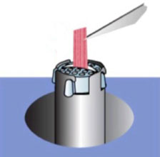
Figure 1: Protocol steps: (A) Unmodified mPrep/s capsule and screen. (B) mPrep/s capsule with 2–3 mm segment cut off the end (dotted line) and discarded (X). mPrep/s screen opening enlarged to accommodate a ∼2 mm thick specimen (arrow). (C) Mounting specimen using mPrep/s Workstation: back end of specimen is inserted into screen slit that clamps the specimen. mPrep/s capsule with end cut off is slid over screen so that the specimen extends several millimeters beyond the capsule. Capsule and screen with mounted specimen is removed from Workstation. (D) Photo of cactus specimen held in modified mPrep/s capsule. (E) Diagram of plunging specimen into cryogen (LN2 slush). (F) Frozen specimen mounted in cryo-microtome. (G) Photo of 4 similar specimens held upright with mPrep/s screen on SEM stubs.
Specimens were mounted into mPrep/s screens by first inserting screens into an mPrep/s Workstation, as diagrammed in Figure 1C. The Workstation mechanism was then used to open and then close the screen slit onto the back end of the specimen (not the specimen end to be imaged). Once the specimen was clamped in the screen in the desired orientation, the modified capsule was then slid down over the screen so that the specimen extended 1–3 mm beyond the end of the modified capsule (Figure 1D). The capsule with the screen holding the oriented specimen was then removed from the Workstation. (Workstation operation can be seen at www.MicroscopyInnovations.com). An oriented and mounted cactus specimen ready for plunge-freezing is shown in Figure 1D. Specimens were kept wet with water throughout mounting and by immersion in water prior to rapid-freezing.
Rapid-freezing was performed by plunging the mPrep-mounted specimen into liquid nitrogen (LN2) slush. Figure 1E shows the capsule was oriented so that the specimen face for cryo-planing was plunged first into the cryogen to ensure rapid-freezing and the best preservation. After freezing, mPrep-mounted specimens were immersed in LN2 while additional specimens were prepared in the same manner.
Cryo-planing was performed by transferring the frozen specimens into the -60 °C chilled cryo-ultramicrotome chuck of an RMC MT 7000 microtome (RMC Boeckeler, Tucson, AZ) equipped with a Boeckeler Cryo System (Figure 1F). Because the polypropylene mPrep capsule is well below its glass transition temperature and because the water in the capsule is solid, the microtome chuck firmly holds the mounted specimen. The specimen was then cryo-planed with a -60 °C chilled glass knife, with the microtome dissecting scope used to determine when a desired tissue region was in view. After planing, the capsule-mounted specimen was returned to LN2 while additional specimens were cryo-planed. As necessary, fresh LN2 chilled glass knives replaced dulled knives.
Once all desired specimens were cryo-planed, they were transferred from LN2 into a pre-chilled freeze-dryer EMS model 750 (Electron Microscopy Sciences, Hatfield, PA), for overnight freeze-drying. After freeze-drying, specimens were gradually warmed to room temperature and removed.
The Workstation was then used to remove the capsules from the screens in reverse of that shown in Figure 1C, except that the specimen remained clamped in the screen. The screens holding the upright specimen were picked up from the Workstation using forceps and attached to SEM stubs using conductive carbon tape. Colloidal graphite was then used to cover and ground the non-conductive polymer screens. Specimens were then sputter-coated with 5–10 nm of AuPd with a Denton Desk I sputter-coater (Denton Vacuum, Moorestown, NJ). Figure 1G shows several similar mounted and coated specimens. Specimens were then imaged in secondary electron mode with an Hitachi S-4100 FE-SEM at 5 KeV.
Results
Multiple Christmas cactus (Figure 2) and canine kidney (Figure 3) specimens were successfully and easily prepared and imaged. These figures show the importance of image plane selection.

Figure 2: Cryo-planed Christmas cactus (genus Schlumbergera) leaf. (A) Faced plane that shows mostly intact cells. (B) Intact chloroplast in leaf section. (C) Faced plane that is mostly through cells. (D) Boxed region shown in C including cross-sectioned chloroplast.
Figure 3: Cryo-planed canine kidney. (A) Cross section of glomerulus. (B) Boxed region of (A) at higher magnification. (C, D) Two additional regions shown at higher magnification.
Cactus leaves
Figure 2, of cactus leaves, shows that image planes can be selected to predominately reveal the surfaces of intact cells (Figures 2A and 2B) or show cross sections through cells (Figures 2C and 2D). The boundaries between individual cells are readily observed in the non-sectioned regions (Figure 2A). In combination with a field of view that also shows a few cross-sectioned cells, the image plane selection provides an overall view of the leaf tissue micro-architecture (Figure 2A). In another specimen region, an intact chloroplast with a textured surface is observed (Figure 2B). The plane of the sectioned face is clearly discerned where the cells are cross-sectioned. This is shown in a low-resolution survey cross section through a different leaf specimen (Figure 2C). Note the many cells, the cell wall structure, and the chloroplasts and other organelles on the membrane faces. A higher-resolution image of the same region shows a cross-sectioned chloroplast and a wavy textured membrane (Figure 2D).
Canine kidney
The images of cryo-planed canine kidney (Figure 3) provide an informative view of the overall micro-renal morphology. A low-magnification survey image shows a cross section through a glomerulus (Figure 3A). A higher-magnification image of the same region (Figure 3B) clearly shows details of cross-sectioned mitochondria and villi. An additional kidney specimen provides a view of a deeply textured villus structure (Figure 3C) and a region of the glomerulus that is dense with mitochondria showing several cross-sectioned cristae (Figure 3D).
Discussion
The methodology presented here enables routine cryo-planing specimen preparation without the need for specialized custom devices. The mPrep/s capsules require only trivial modifications and, with the Workstation, enable facile orientation of the specimens. The capsules provided an easy-to-manipulate handle for the entire preparative process. The capsule “holder” also reduced the potential for specimen damage since the specimen itself did not need to be directly held. Because a standard cryo-microtome was used for cryo-facing, it was easy to view and control the location of the cryo-section plane or face. Finally, because multiple specimens held in mPrep screens may be mounted on a single SEM stub, it was easy to view and record comparison images in the SEM.
In the present study, aldehyde-fixed kidney was used. Fixed tissues provide both advantages and disadvantages. It is well known that rapid-freezing of fresh tissue can provide the highest possible morphological preservation, but it is imperative that the tissue be extremely fresh, and logistically this can be difficult to accomplish. Thus, pre-fixed tissue can be advantageous. An additional advantage of aldehyde pre-fixation is that this makes the tissue a bit tougher and firmer, which can facilitate dissection and mounting in the desired orientation. In the present study, the kidney tissue was also post-fixed in OsO4. This improves membrane fixation and also makes the membranes no longer osmotically active so that specimens can be washed in pure water, reducing the potential appearance of salt deposits on the specimen. The OsO4 fixation can also provide electrical conductivity. Osmium tetroxide fixation when combined with mordents such as thiocarbohydrazide and tannic acid can even provide sufficient conductivity to enable high-resolution SEM without metal coatings [Reference Murakami9]. Thus, it may be possible to extend this method to minimally coated or even uncoated specimens.
This cryo-planing methodology using mPrep capsules and a cryo-ultramicrotome could be modified by rapid-freezing in cryogens other than LN2 slush, such as chilled ethane or propane [Reference Van Dongen4,Reference Murakami9]. The present methodology could also be adapted for frozen-hydrated SEM imaging, wherein cryo-planed specimens are transferred to a cryo-coater and thence to a cryo-SEM [Reference Njisse and van Aelst1,Reference Walther2].
While the present specimens were about 2–3 mm thick and 5 mm long, the mPrep/s capsules readily accommodate specimens as thin as 100 µm. Smaller and thinner specimens can improve the freezing rate and thus potentially improve image quality and/or volume of the vitreous frozen region. The capsules can also accommodate specimens that are even a few millimeters larger than those used here, but of course there are limits on the rate of freezing with larger specimens, which can have deleterious effects on the quality of the preparation of hydrated biological specimens. However, this would not be an issue with non-hydrated specimens where one wants to prepare cross sections, such as polymers, composites, pharmaceuticals, and other materials.
Conclusions
The methodology demonstrated here provides ease, quality results, and experimental flexibility for the preparation of cryo-planed plant and animal tissue specimens. Because the process is accomplished with a conventional cryo-ultramicrotome and readably available mPrep/s capsules, this method can be easily performed in many labs. This could enable cryo-planing to be done more easily and more routinely in the examination of biological and many non-biological specimens.


