

Edited by Thomas E. Phillips
University of Missouri
Selected postings from the Microscopy Listserver from January 1, 2014 to February 28, 2014. Complete listings and subscription information can be obtained at http://www.microscopy.com. Postings may have been edited to conserve space or for clarity.
Specimen Preparation
LR White
We find strange bubbles when embedding Bacillus subtilis bacteria in LR White resin. The bubbles prevent the resin from polymerizing. Does anybody have an idea how and why this could happen? Examples can be seen at http://chimerism.medunigraz.at/Pictures/pioloform02.php Stefan Wernitznig stefan.wernitznig@medunigraz.at Tue Jan 21
These bubbles seem to be trapped air in the resin. Put the specimens in the final resin in the embedding capsules and leave them for an hour. The air bubbles will come to the surface and you can easily break them with a needle. Then put the capsules to the oven for polymerization. Berillis Panagiotis pveril@apae.uth.gr Tue Jan 21
By chance did you happen to post fix the bacteria in osmium tetroxide? LR White does not polymerize well when osmium is used in the processing protocol. Mary Ard maryard@uga.edu Tue Jan 21
Those don't look like air bubbles to me. They look like something extracted from the bacteria. Maybe your samples are not fully dehydrated? Perhaps there is still some non-miscible solvent present. Air bubbles shouldn't prevent LRW from polymerizing. Does a "blank" block with no cells polymerize? Tom Phillips phillipst@missouri.edu Tue Jan 21
I agree with Tom, that it looks as if something has been released from the bacteria. It could be lipid being extracted by the resin, which is a pretty good solvent. I am not sure that this is the reason why the resin has not polymerized. From your images, it does look as if you have used osmium tetroxide to contrast the cells. It might also be possible that you also used acetone to dehydrate the cells. Residual amounts of acetone may have interfered with resin polymerization in the way you describe. A more detailed description of your processing and embedding protocol may help diagnose the problem. Paul Webster paulwebsterphd@gmail.com Tue Jan 21
We agree with those people who think that the "bubbles" have to do with something extracted from the bacteria that prevents the resin from polymerizing. We did not use osmium. We dehydrated in ethanol up to 80% ethanol and did not degas the resin. We used a premix resin that works OK with any other specimens except bacteria. But we do not add the extra accelerator. Perhaps the next steps will be: (i) to dehydrate up to 90 % alcohol (ii) degas the resin (iii) add extra accelerator so that whatever chemical reaction we have might not occur? Any suggestions are welcome and thank you again! Stefan Wernitznig stefan.wernitznig@medunigraz.at Fri Jan 24
Since bacteria are usually plentiful and inexpensive, I would also do one sample after 100% ethanol to see if it is due to residual water. Degassing the resin can change composition since you can differentially extract the more volatile components. Tom Phillips phillipst@missouri.edu Fri Jan 24
I do not remember seeing how long your steps were during dehydration in ethanol but do know that these little bacteria take longer than anticipated to dehydrate. I have also found it advantageous to have the ethanol moving by putting the tubes on a tilting table or to rotate them during dehydration and also for the infiltration steps. I have had similar looking bacteria in macrophages embedded in Epon in the past. After the first paper was published I learned that my problem was their dehydration. The macrophages themselves looked fine when processed by my standard tissue culture protocol but the Listeria within them turned very dark and peppered like yours when the beam hit them. After I started to use our longer protocol for tissue samples, the bacteria looked great. Many years ago I was advised to go through 90% ethanol when using LR White so your suggestion to do that is a good one. One can introduce air/oxygen into the embedding media when stirring in the accelerator so degassing could help in the elimination of that possibility. I usually harden the LR White in a 45°C oven for a few days without accelerator so I cannot address the possibility of adding an additional amount of accelerator. Patricia Connelly connellyps@nhlbi.nih.gov Fri Jan 24
Specimen Preparation:
agar
The agar that we are currently using to secure cell pellets is causing a really annoying background all over the sections both inside and outside of cells. This is a terrible graininess that we have seen now in several preps. What we have is bacterial grand from Applichem. We are pretty sure this is the cause of the graininess. Can anyone recommend another agar or another means of securing cell pellets? Sometimes users of our core can provide only small quantities of cells. Thanks in advance for suggestions. Marcia M. Miller mamiller@coh.org Thu Feb 13
We have been using the low-melting-point agarose (not agar). It works great. You can find it at Sigma (Cat# A9414). Zhaojie Zhang zzhang@uwyo.edu Thu Feb 13
We have encased small fragile objects between Formvar films on a wire loop. Although this does require appropriate obeisance to the Formvar Spirits, the outcome in terms of structure preservation is excellent. You can read about it in Wu et al. 2012 Nature Protocols 7: 1113- 1124. Tobias Baskin baskin@bio.umass.edu Thu Feb 13
We use 1.5% agarose in PBS (I assume other medium works too). We first mix the agarose with PBS in an Eppendorf tube, and then immerse the tube in boiling water for a few minutes. The agarose would be completed 'melted' at this point. We then transfer the tube to a 37°C water bath, to let it cool down to 37°C. The agarose (melting point 36°C) will stay melted at 37°C. We then mixed 1 part of cells and 1 part of agarose at 37°C, then bring the mixture to room temperature. The mixture will become solid right away (no need for ice)! Zhaojie Zhang zzhang@uwyo.edu Thu Feb 13
Specimen Preparation:
negative staining problem
I’ve been doing some negative staining and am experiencing some problems with the Formvar film falling apart on the grid. I’ve been using 200 mesh Copper Formvar/carbon-coated grids which are a couple of years old – does anyone know if these grids have a certain shelf life? My technique has been to put a drop of the protein (in HEPES buffer) on the grid, blot dry, add a drop of uranyl acetate, blot dry and then let the grid air dry. When I view the grid on the TEM, pretty much all the Formvar is gone. I haven’t done a lot of negative staining in the past so any comments/suggestions would be greatly appreciated. Thanks much. Pete Finger pete.finger@jax.org Fri Jan 31
Films on grids do tend to break when old. I used some 75 mesh grids that were 5 years old recently and they were still good but I'd not try to use single holed ones that were that old unless I really needed to. With older 200 mesh grids one can usually get some areas that do not pop but use newer ones if you can afford them or make them yourself. Perhaps your drying step is a bit harsh. The word "blot" is what caught my eye. It is hard to judge unless it could be observed. I was taught to do my negative staining differently than how you describe. I put a sample onto a recently glow discharged grid held in forceps, let it sit for 30 to 60 seconds, gently drop 5-6 drops of 1% uranyl acetate (UA) from a pipet onto the surface of the grid held perpendicular to the grid (grid parallel to the table top over a vessel to catch the UA). After the last drop of UA is on the grid I touch a point of filter paper to the junction of the forceps where the grid is being held to slowly wick the UA off. The surface of the grid will still be wet. There is usually a small amount of UA between the forceps tips so I "push" the grid out of the forceps with the same piece of filter paper using another portion that is not already wet, onto some lens tissue to continue to dry completely. There are many different techniques in doing negative staining. Once you find one that works for you, that is the one you should stick with. Pat Connelly connellyps@nhlbi.nih.gov Mon Feb 3
Specimen Preparation
ZnO film for TEM
How can I prepare a sample of ZnO thin film deposited on glass substrate by RF magnetron sputtering, so I can analyze it in TEM? Is there any published method or does somebody know an easy way? Rubén Ahumada-Lazo rub.ahumada.lazo@gmail.com Thu Jan 9
The easiest and fastest way would be to deposit your coating on a #0 or #1 glass cover plate and use a slightly modified version of the small angle cleavage technique. When you start scribing with the mini scribes, some pieces will have a small angle and will be good specimens when you mount them on the grid vertically. For ZnO, the transition region from equiaxed growth to columnar is weak and you often get a jog in the cross section of the film with the columnar structure back further from the tip. It just means that you have to screen more samples in the microscope. Get your hands on the MRS vol 480 book for Sample Prep IV and look at John McCaffrey and my paper. The Small Angle Cleavage Technique: An Update, S. D. Walck and J. P. McCaffrey, Proceedings of the Materials Research Society, Workshop on Specimen Preparation for Transmission Electron Microscopy of Materials IV, eds. Ron M. Anderson and Scott D. Walck, Vol 480, Pittsburgh, (1997). I think that we talk about ZnO results in this paper, but I'm not 100% positive: The Small Angle Cleavage Technique Applied to Coatings and Thin Films, S. D. Walck and J. P. McCaffrey, Thin Solid Films, 308-309, pp. 399-405, 1997. Scott D. Walck s.walck@comcast.net Sat Jan 11
Specimen Preparation
chromium sputtering target
We have a Denton DESK II Turbo Sputter Coater and are planning to use a chromium sputtering target for the first time. We intend to use this coating for FESEM observation of a variety of specimens. We are familiar with gold and gold-palladium targets but never used a chromium target before. This morning we coated a sample with chromium, but seems like it didn't get any coating at all. I did see the plasma. When we use gold or gold-palladium in the same coater, it works fine and we can see the coating on the surface. Is it possible to see a color difference after Cr coating for 60-100 sec. We are using 40-60% power. I noticed the Cr target is much thicker than the gold target. I will appreciate someone telling if we are doing something wrong or it is just our simple ignorance about chromium target. Soumitra Ghoshroy ghoshroy@sc.edu Fri Feb 28
I do not know the Denton Turbo Sputter Coater, but I was involved with the development of Chromium coating many years ago! To sputter chromium is not like sputtering any of the more familiar materials. Firstly, you need a high vacuum and a power supply that is rated much higher than for the conventional sputtering materials. Secondly, before you are able to sputter the chromium the oxide coating has to be removed, and this has to happen every time you use the unit. So the first part of the sputter process is oxide removal, most dedicated systems have a shutter to catch the oxide, thus leave the specimens clean. You know when all of the oxide has been removed as the plasma will have a nice pale blue color. Once you have this level of target cleaning you switch off the plasma, remove the protective shutter, and coat for about 2 to 5 seconds. You should not expect to be able to see the coating. It's a very long time since I was involved with this work but I hope I have been able to provide some assistance? Steve Chapman protrain@emcourses.com Fri Feb 28
As a compromise might I suggest using Pt, it will definitely give you better results than Au or Au/Pd. John Robson john.robson@boehringer-ingelheim.com Fri Feb 28
Chromium is extremely reactive with oxygen. Even with a UHV system, chromium deposits tend to be chromium oxide. The best way to deposit chromium is with an ion beam sputtering system. Plasma sputtering, as you have discovered, does not work well for chromium. You see the glow of the plasma, but not much else happens. John Mardinly john.mardinly@asu.edu Fri Feb 28
Microtomy
diamond knife sharpening
Has anyone out there actually seen how the diamond knives are resharpened? I wonder if there is a tool and a training to attempt it. We have so many and it is difficult to buy them for us. Anyone also know of a company that takes several knives in exchange for a knife? Like giving up 3-5 knives for a new one? Nick Madary joseph.n.madary.civ@mail.mil Wed Jan 29
Diatome diamond knives will replace a used knife (any size) for a brand new knife (any size) at half the cost of a new knife. Believe me, this is the best deal I know of. If you find a better one, let us all know. Michael Delannoy delannoy@jhmi.edu Wed Jan 29
Diatome has a deal where if you send in three knives for re-sharpening, they will charge for two of them at the re-sharpen price and the third one is free. Since you have many knives it might be advantageous to keep a few sets of three so when you send one set in you will have another to work with. Lita Duraine duraine@bcm.edu Wed Jan 29
Years ago, a knife vendor gave a talk on how diamond knives are sharpened. It is not hard, but takes 1-2 weeks of grinding on a diamond grinding wheel. This is not something that you can do in your leisure. I once asked another vendor this same question about giving them three or four knives and get a new sharpened knife in return. After picking themselves off the ground from laughing so hard, they explained to me that the diamond is about 40-50 dollars. It is the time it takes to sharpen the knife that cost so much, so they will not just give a sharpened knife with exchange of 3 or 4 knives. One of the vendors does give a discount for a 2 for 1 exchange. Call them up and ask about this. Best of luck convincing the powers that be to purchase a knife for you. Ed Calomeni edward.calomeni@osumc.edu Wed Jan 29
Immunocytochemistry
non-specific antibody interaction
I am having a bit of a problem, and would like to know if anyone has any suggestions as to how I could possibly improve my results: I am attempting to label two antigens in the same sample. Unfortunately, both these antigens are monoclonal mouse, though one is IgG 1and the other is an IgG 2. Both appear to bind fine when I put them into a sample with both antigens present, though there is no appreciable change to the label distribution when the same process is applied to a sample that supposedly has only one of the antigens present. If anyone can supply some thoughts as to how I might increase binding specificity in a sample, that'd be great. We've tried using a high salt washing buffer for this, as well as trying to pre-bind the primary antibodies to their markers, though nothing seems to change our results. Any suggestions are greatly appreciated! David Parmiter parmiterd@mail.nih.gov Mon Dec 23
David informed me off list as follows: “Our primary antibodies are mouse-derived monoclonal antibodies IgG1 and IgG2a. The secondary antibodies we're using are goat anti-mouse IgG1 and Rabbit-anti-mouse IgG2a, and we label these with gold conjugated tertiary donkey antibodies.” A three step approach using donkey conjugates sounds ok, but it all depends of course on how specific the individual components are. Have you tested this? I am thinking of a simple dot-spot test, but you could also do this on specimens. To solve the issue I would start from the tail of the incubation procedure (the gold conjugates) and work forwards towards the primaries. The procedures would be as follows. All controls should of course be negative.
1. Controls where the specimens are incubated with only the gold conjugates, separately as well as together. If those are ok, then proceed with step 2.
2. Controls where the specimens are incubated
a. with secondary1 and gold1 (matching pair)
b. with secondary2 and gold2 (matching pair)
c. for cross reactivity between secondary1 and gold2 or between secondary2 and gold1
d. for any reactivity between primary and gold conjugates:
primary1 and gold1
primary1 and gold2
primary2 and gold1
primary2 and gold2
If these are ok, then proceed with step 3.
3. Controls for cross reactivity:
primary1 and secondary2 and gold2
primary2 and secondary1 and gold1
It is tedious, but with three step incubations and double labeling, it cannot be avoided if one wants reliable answers. This will be the way to establish specificity on specimens. The dot spot tests would be based on the same approach. Jan Leunissen leunissen@aurion.nl Mon Dec 23
Imaging Software:
end of support for Windows XP
April 8, 2014 marks the end of support from Microsoft for Windows XP. That means no more security updates to patch newly discovered security holes. This will leave any computers still running Windows XP vulnerable to attacks if they remain connected to the internet or if infected memory media are inserted into the computer. I am sure there are a lot of machines out there running Windows XP. I am curious to hear what approaches microscopy community members are taking to deal with this, as well as what the community of microscopy related hardware vendors are doing to address this situation. John Mardinly john.mardinly@asu.edu Wed Jan 15
At my place, we are putting a Win7 computer between the XPs and the corporate network. The Win7 will act as a server for the XPs. We have a few SEMs and a couple of other tools that cannot be upgraded to Win7. Unless, of course, we want to buy whole new tools! Becky Holdford r-holdford@ti.com Wed Jan 15
We are keeping our XP machine unplugged from the network, and I made sure to turn off "autorun" for all media (CD/DVD and USB) so infected media can't take over your machine automatically (unless there's a new way to get Windows to automatically execute files, which wouldn't surprise me). Nick Botto nwbotto@ucdavis.edu Thu Jan 16
As an addendum to this, Microsoft announced on January 15th that it would continue to provide updates for security products until July 14, 2015. So no more system updates, but at least they'll continue to update Security Essentials and other MS antivirus signatures for machines running XP. http://thenextweb.com/microsoft/2014/01/15/microsoft-extends-updates-windows-xp-security-products-july-14-2015 Adam Schuetze adamschu@uvic.ca Thu Jan 16
Imaging Software:
ChromaCal
I was just reading the article in the January 2014 Microscopy Today issue on standardizing color in digital images using the ChromaCal microscope slide and monitor calibration system. Interesting idea but I have a question. I know the authors Barbara Foster and Jerry Sedgewick participate on the listserver so I thought I would post it here for feedback from both them and others who might have used the system. The website for Datacolor states "The CHROMACAL slide is not suitable for use with oil immersion objectives" but Figures 1 and 4 in the Microscopy Today article were made with oil immersion objectives. The system looks to cost around $1000 so this won't be an impulse purchase for most of us. Anyone have experience or thoughts on this? Tom Phillips phillipst@missouri.edu Mon Feb 10
True, the ChromaCal slide is not suitable for oil immersion objectives. The slide has no coverslip on the chip, and cleaning may damage the calibration matrix. Figures 1 and 4 were taken using an oil immersion lens for the sample, and a dry objective was used to image the ChromaCal slide. I found I could get equivalent results regardless of the objective used, as long as I kept the white balance the same and set Koehler illumination. Having run a light microscopy lab for 15 years, the issue of color inconsistency and inaccuracy led me to attempt making a color calibration slide on my own. I simply could not get the filters small enough for a microscope. Thus, my delight in working with a company that has accomplished it at this scale. To make things even better, I can do morphometry now using consistent color as a means to segment images. Thanks a million for pointing out the disconnect in the article! Jerry Sedgewick jerrysedgewick@gmail.com Tue Feb 11
Image Processing:
pseudocoloring
We've just updated our image processing instructions here at the NUANCE Center from Northwestern University. These instructions are super easy to use and walk the user step-by-(sometimes painful) step to do all sorts of normal image processing procedures one might normally come across, from adjusting levels, to calculations, to some totally cheating techniques of drawing a mag line marker, to several different procedures to apply false color to an image. The extra special part is the chapter on what I call Multi-Detector Color. Now I know I did not invent this technique, but I've worked out some pretty simple procedures that will allow you to make these really fantastic color images, even if you only have 1 SE detector in your SEM. It's totally free, so please check it out and let us know if you have corrections or suggestions. http://www.nuance.northwestern.edu/docs/epic-pdf/Basic_Photoshop_for_Electron_Microscopy_2014.pdf. Eric Jay Miller eric-miller@northwestern.edu Tue Feb 18
Image Processing:
montage software
Does anybody know of software for building montage images for a Titan TEM? We would like to build a large image from a multitude of high resolution plant cell images. Pete Eschbach peter.eschbach@comcast.net Tue Feb 18
I use ImageJ for that, not sure if it's suited for your type of images though. Nick Botto nwbotto@ucdavis.edu Tue Feb 18
The ImageJ plug-in MosaicJ is pretty easy to use and allows big images. I believe you need the TurboReg plug-in installed as well, as it can automatically stitch as long as you put them down close to the right position. I've used it successfully several times. Larry Scipioni les@zsgenetics.com Tue Feb 18
I've used the GIMP for this application with a lot of success. Something else to look at would be this: http://research.microsoft.com/en-us/um/redmond/groups/ivm/ICE/ Jacob jkabel@mail.ubc.ca Tue Feb 18
I have used the commercial program Corel Photopaint (part of the Coreldraw suite of programs) extensively over the years for TEM and other montaging. It is manual montaging, but it handles any file size (I have done up to montage around 300 GB), and it has a feature where the selected image is subtracted from what is under it, meaning you can quickly see which parts of the image are aligned because they go completely black. The programs others have mentioned are also good options. Duane Harland peter.eschbach@comcast.net Tue Feb 18
A number of options to stitch existing images has been discussed already - if you are interested in software that drives automated acquisition to build montages, have a look at SerialEM (actually a tomography software): http://bio3d.colorado.edu/SerialEM/index.html It works on the Titan platform and can also do the stitching. Guenter Resch lists@nexperion.net Wed Feb 19
The Montage building software you use will be dependent not so much on the microscope but how the images are named and in what order they are collected. If you are using a FEI Eagle camera, you will need to convert the proprietary image format to .tif or .jpg then proceed. GIMP does this well. We use an AMT camera and the images are automatically named according to their x-y position in the montage, for example 0006R1C6 refers to an image in the first row and the sixth column. How the stage moves from one image to the next during collection is essential information. We have used Adobe Photoshop for image montages, but it is slow compared to FIJI and may not complete large montages. For montages up to 19x19 images, I would suggest using FIJI. For image sets of this size you will also want a 64 bit operating system with exceptional graphics capabilities. Download Fiji (http://fiji.sc/wiki/index.php/Downloads). Fiji is a distribution of ImageJ together with Java, Java 3D and several plugins organized to assist research in life sciences, targeting image registration, stitching, segmentation, feature extraction and 3D visualization, among others. Using FIJI you can direct the program to the folder in which the images are stored and also define the naming nomenclature so that the montage software will find each successive image. There is quite a bit of flexibility built into FIJI as to how the program finds the images; we have had the most success with the position defined by the file name. Once you download FIJI, bring up the screen where images in this format can be loaded (FIJI/Stitching/Deprecated/Stitch grid of images). I would be happy to send a word document with specific instructions with screen shots on how to work with images in this format to anyone who might find it useful. Doug Keene drk@shcc.org Wed Feb 19
There are many montaging programs. I can suggest PTGUI which some of our SEM users have used for montages with hundreds of images. It is not picky on the filenames, file types, and/or file order. PTGUI stands for Panorama Tools (Graphic User Interface). Jim jquinn11733@gmail.com Wed Feb 19
LM:
source of diffraction
I am trying to hone my understanding of diffraction in microscopy: particularly the slit diffraction analogy and how diffraction affects resolution in microscopy. 1. If you take a sub-resolution point source of light (GFP molecule) and image it through an objective, you get a central maximum and a series of concentric disks due to diffraction during image formation. Question- What is the source of the diffraction? There are no slit like openings that are less than the wavelength of the light. I am presuming this diffraction is due to light diffracting at the edges of the objective? I could not find a good written/diagrammatic description of the issue- can someone point me to one? 2. The separation of Airy disk central maxima as an explanation for resolution makes some intuitive sense, but is only taking account of the NA of the objective as if there are no other sources of diffraction other than the objective. This would be reasonable for a purified fluorescent molecule/protein attached to a coverslip. However, in cells, you now add many other sources of diffraction as light passes into and out of a cell. So would it be more correct to say that the calculated resolution is a maximal or optimal resolution? I am presuming that this is routinely not achieved in cell/tissue imaging? Do we have an estimate of how much resolution is lost by a molecule being in the middle of a cell (i.e., what you get from a single super-resolution activated molecule in PALM) as compared to a purified molecule in isolation? Presumably you can back calculate this from the actual diffraction pattern measured for single activated molecules in a cell vs. in isolation? David Knecht david.knecht@uconn.edu Fri Feb 14
1) Actually the Young’s slit experiment doesn’t require the width or the distance between the slits to be less than the wavelength of light. You can do it using a slide that you’ve put a thin black coating on (using model airplane paint for example) and then scratch it twice with a razor and shine a light through it. If you do your trigonometry, you’ll find out that if you put the slits really close (as in a few hundred microns or even a mm) you can see the diffraction pattern pretty clearly some feet away. In a microscope, you have apertures, and tubes bounding the light path and that is what is causing your diffraction. If you are operating at high NA then often the limiting aperture is the objective. You’ll get diffraction whenever the light path from one side of the aperture is on the order of one wavelength of light different than in the middle of the aperture, practically speaking, high mag. 2) Point resolution limits described by airy disks etc are really rules of thumb. As you note, the resolution limit is the smallest feature you can separate from your image, nothing more or less. Usually that is much less than the Airy resolution due to inhomogeneities in the sample, like you describe. On the other hand, theoretically, if you know exactly the diffraction characteristics of your entire system, and your sample is composed of point sources, and you have infinite signal to noise, you can separate two different points that are infinitely close together. You can make a quick demonstration with Matlab or a similar program by plotting two Gaussians with full width at half maximum (FWHM) of 100 units, and centroids separated by 1 unit, and then do a fit to extract the separation between the two centroids. You won’t have any trouble even though this scenario is resolving peaks far, far below the "resolution limit." As soon as you add even a little noise, you cannot make the fit work. As soon as you allow for any uncertainty in the FWHM or skewness of the peaks, then you also can’t get a good number from your fit. I encourage you to try this, actually, it is very informative just how little noise or uncertainty in the peak shapes is required to destroy your ability to resolve the two peaks, and if you play with it for a while will wind up deriving a practical resolution limit “law” of your own. Chances are you will wind up with a limit not far from the FWHM of the Gaussians. If you like programming you can do this with Airy disks and you’ll “reinvent” the Airy resolution limit. In a real microscope, you always have some aberrations, and your sample always has some inhomogeneities (otherwise why are you looking at it?). So the Airy resolution is a very practical limit and very useful, but there is no deep fundamental reason why the grand master of the universe says that’s the resolution limit. It’s just a good demarcation that was chosen based on a reasonable application of diffraction through an aperture. I hope this helps! Zack Gainsforth zackg@berkeley.edu Fri Feb 14
TEM:
unknown particles
During an electron microscope examination of Sparus aurata liver collagen (PTA and uranyl acetate were used as stains), I came across to these objects. They are probably virus particles. Can anyone identify them? http://upload.users.uth.gr/files/virus.jpg Berillis Panagiotis pveril@apae.uth.gr Thu Jan 23
What is the average size of the "particles"? You do not have a size bar in your image to get a feel for their size, which is important in any viral identification. The "particles" do not appear to be associated with the sample on the grid but lying on top of the sample. In my opinion, they look more like crystalline structures rather than viral particles. Depending on their actual size, could they possibly be phosphotungstic acid crystals? Mary Ard maryard@uga.edu Thu Jan 23
Giving a picture without scale to a miscroscopist is like talking without words. We cannot make anything out if it! I doubt these objects are embedded in the resin. One can see a hole in the section and one object seems to partly cover it. Also they don't look like they were sectioned. Looks like artifacts for me. Stephane Nizets nizets2@yahoo.com Thu Jan 23
I agree, it does not look like belonging to section. There is some contamination after sectioning/staining. I have stained a lot with PTA but have never seen anything like this. Vladimir Dusevich dusevichv@umkc.edu Thu Jan 23
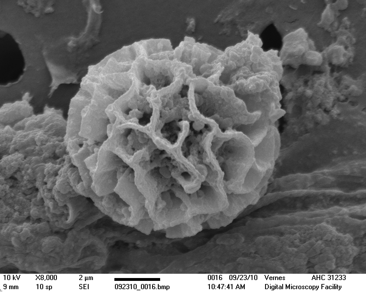
Depending of course on the scale, this looks a lot like a bunch of fungus spores, similar although not identical to: http://www.mta.ca/dmf/download/jme/092310_0016.bmp Maybe somebody was eating a bacon-mushroom burger in the microtomy area. Jim Ehrman jehrman@mta.ca Thu Jan 23
Yes, scales are different, yet it is remarkable how much your particles resemble to pollen I have a picture from a wild flower pollen that looks very close to these particles http://www.eikonika.net/v2/downloads/KITSTI03_resize.jpg. Unlike in the North America, spring came earlier in Greece this year. Yorgos Nikas eikonika@otenet.gr Thu Jan 23
Both spores and pollen are a way too big to be transparent under TEM beam. Vladimir Dusevich DusevichV@umkc.edu Thu Jan 23
I take it that these are sitting on a film and are negatively stained with both uranyl acetate and phosphotungstic acid? They look vaguely like something tentatively identified as scales from some sort of phytoplankton that we often see in marine preps. They do not look like any of the many marine viruses we've seen here, but I will show them to someone who works on marine viruses and see what they say. However, right now I'm going with the idea that they are stain crystals! Tina (Weatherby) Carvalho tina@pbrc.hawaii.edu Thu Jan 23
Yes, pollen was my immediate thought, but pollen would be at least one, probably two, order/s of magnitude too big! Rosemary White rosemary.white@csiro.au Thu Jan 23
The objects you have seen under your EM are not virus or pollen; they are Brochosomes. Brochosomes are secretory granules produced by the Malphigian tubules of leafhoppers. You may have a look at the Wikipedia article concerning this unfamiliar but beautiful structure (wikipedia.org/wiki/Brochosome). I have seen EM pictures of this structure many years ago, since it has been once described in the sixties by my former colleagues in the lab in Rennes (France, Brittany). (Gouranton J. & Maillet P.L., (1967) "Origine et structure des brochosomes," Journal de Microscopie 6: 53-64.). Brochosomes are source of contaminations and can sometimes be found in aerosol (Wiffen R. D. & Heard M. J., (1969) "Unidentified airborne species," Nature 224: 715). I recommend the readings associated with the Wiki article. However, if you are interested, I can look over the archives of the lab and try to find original negatives. Daniel Thomas daniel.thomas@univ-rennes1.fr Sat Jan 25
Merci Daniel for showing these brochosomes, they have a very smart shape. A pattern repeated in many structures seen at different scales in this wonderful world. And I am sure you gave the right answer. Yorgos Nikas eikonika@otenet.gr Sun Jan 26
TEM:
diffraction of amphibole fibers and fiber bundles
I have a Mineralogy student working in my lab on the TEM trying to obtain diffraction patterns (SAED) on amphibole fibers and fiber bundles. Note: some of the specimens may be cleavage fragments. Particle size: 50-100 microns short dimension & 100s of microns in the long dimension. Our microscope is a JEOL 2010 at 200kV. We are having a surprising difficult time getting any reasonable SAED patterns on these. We can get reasonable and nice patterns on adjacent micas in the sample but nothing of use on the amphiboles. Different spot sizes, SAED apertures, camera lengths, etc. No joy. We should be able to do this, even though I am not the world’s best at electron diffraction. Tom Williams tomw@uidaho.edu
50-100 µm is very thick for SAED. You are probably not getting the electrons through the sample, whereas, the micas are probably thinner. The thing to try is getting diffraction patterns from the very thinnest edges of the fibers. You could crush the sample further, but that would destroy the measurement of length-width aspect. If you have EDX, you can correlate composition of the crushed sample patterns to as-received samples. Hope this helps. Ken Kenneth JT Livi klivi@jhu.edu Fri Jan 24
Are the samples are thin enough for TEM? Your description sounds a lot like the fibers are too thick, they need to be less than half a micron thick to allow you a chance to get results. Cleavage is a great technique but you might need to do it twenty times to get something decent. Rob Keyse rok210@lehigh.edu Fri Jan 24
In bright field look for areas that exhibit bend contours. Those are the areas that are thin enough where you can find a reasonable pattern usually at the terminations. Find fibers that are elongated in the direction of the tilt axis, adjust the height of the sample so you can tilt without the fiber moving. Tilting about the long axis which is [001] you can see the closely spaced spots of 010. Tilting about 010, ideally you should find [100] and [101] about 30° apart. Easy to find in the orthorhombic amphiboles and less easy in the monoclinic amphiboles. I suggest practicing with IUCC standards. Tremolite and anthophyllite. Also with Dave Palmer's Single Crystal program you don't need a TEM. Getting indexable diffraction patterns off fibrous amphiboles requires patience which is why asbestos labs don't do it. Gordon Nord gnord@mindspring.com Fri Jan 24
TEM:
grid without Zn and Ni
I'm looking for TEM grid, 3.05 mm diameter, 200-mesh, carbon-coated (about 200 A carbon thick) absolutely without impurity of Zn and Ni because I have to investigate (by EDS-TEM) on synthetic particles containing either Zn as Ni. I already tried the Au, Cu, plastic grids and all contain some amount of at least one of these elements. I verified that the grids sold as Cu-grid contain either Ni as Zn. Do you have info on carbon coated grids with the characteristics I need? I hope you can help me because I don't find a solution for this problem. Elena Belluso elena.belluso@unito.it Thu Jan 9
I would be surprised if the stray EDX signals were coming from your grids. They are generally quite pure (at least at the TEM EDX level). TEM EDX detection limits will be a few tenths of an at% and grid impurities will be more in the ppm level. Also, the fact that you are seeing stray signal from many different grids suggests that the grids may not be the source. The only time I’ve ever seen impurities by EDX was a silicone contaminated C film where the diffusion pump oil backstreamed into the chamber during the film preparation. That batch of films showed huge Si contamination. So, where is the stray signal coming from? I would suspect that you are seeing fluorescence from hard x-rays (bremsstrahlung) generated when the beam hits the C2 aperture. The bremsstrahlung will cause areas away from the sample in the sample chamber to fluoresce. This can be tested by putting the beam through a hole in the sample (called a "hole count"). In this case you should have no EDX signal at all. If you do see something, it is likely caused by the bremsstrahlung generated fluorescence. Henk Colijn colijn.1@osu.edu Thu Jan 9
You may wish to consider using SiN windows mounted on thin Si wafers. These are available at most EM Supply houses. I have used these for supporting small particles and have successfully done XEDS on these for years. You will, of course, detect Si, N, and some O. I have never seen Zn or Ni with these SiN films in instruments here at the ANL EMCenter. Look for Si wafers ~ 100 microns thick, rather than the thicker (200 -300 micron) ones. The SiN windows range from 10-100 nm, obviously the thinner the support window the better, but admittedly the 10nm thick windows are fragile. Just be careful, or start with thicker windows and work your way down. Finally, be cognizant of which side you deposit your particles and also which side is facing your XEDS detector, in order that you do not get any shadowing effects due to the penumbra of the stage and/or the chemically etched Si surface. Nestor Zaluzec zaluzec@aaem.amc.anl.gov Thu Jan 9
Have you considered that the Zn/Ni could be coming from the TEM or sample holder (or even the EDS detector) rather than the grid itself? When you hit the sample with high energy elections, you generate a huge number of x-rays of all energies in addition to backscattered electrons. If you have any brass near your sample, you are almost guaranteed to get Cu and Zn in your EDS spectrum from non-local fluorescence. The Ni could be coming from SS near the sample or the TEM pole piece (do you also see Fe?). While TEM based EDS is a lot cleaner than it once was, you can never really be sure where the x-rays that enter your detector originate. Using low background holders and TEM hard x-ray apertures (if available) can help. Chapter 33.3 in Williams and Carter's TEM book details these issues and describes precautions to help reduce system and spurious x-ray artifacts. If you have access to an EELS detector, you can run the experiments without worrying about fluorescence artifacts. You will only see the element if it is under the beam. Ray Twesten ray.twesten@sbcglobal.net Tue Jan 14
EDS:
can't detect tin
We are trying to use FEI Technai Orisis TEM to characterize the element distribution of a zirconium alloy with 3.5 atom% Sn. However we can't detect tin anywhere with EDS in STEM Mode with beam spot 9. The EDS system works very well for a ODS steel. We have tried our best to figure out this problem, but we failed. Any comment and suggestion would be appreciated. Hongbing Yu 12hy1@queensu.ca Tue Feb 4
This may sound like a silly suggestion but if you haven't already, I would try the following things: 1) Use an enormous beam in TEM mode to look around on micron-scale and look for Sn in EDS all over any thin area. You may just be looking at an unusual part of the specimen where the Sn is gone and not know it. 2) If you can do EELS, check for Sn there - should be an M edge about 500eV I think (look in EELS Atlas, I am being vague). If you cannot see Sn anywhere by EELS or EDS then the problem is not the EDS detector, the problem is that your specimen doesn't have Sn in it, and you now have to figure out why. Preferential removal of Sn during sample preparation? Something happened when making the material originally? Jo Sharp j.sharp@sheffield.ac.uk Wed Feb 5
TEM:
pneumatics errors
Upon turning on our CM10 for the first time after the install there is a message saying "Pneumatics". I can't seem to get the ODP to turn on, and twice now the viewing glass has been pushed out by the compressed air. Does anyone have any ideas on what the problem may be? Josh Schorp jcsmtf@mail.missouri.edu Fri Feb 14
I have not been able to activate the HIVAC and UHV on our CM10. The pressures of the Pirani gauges are: P1=82, P2=19, P3=0, IGP=0. This is after the pre-vacuum has been running for roughly 20 minutes. Once the pre-vacuum is turned off, P2 goes to about ~70. Is it normal to take longer than this to get the P2 down below 13.3? Josh Schorp jcsmtf@mail.missouri.edu Fri Feb 14
A "pneumatics" error message generally means that your air pressure is too low to operate the valves of the microscope. The FEI TEMs generally want to have ~6 bar air pressure. If your viewing window is being forced out, it sounds like you may have a more serious problem than the pneumatics error. The viewing chamber is not supposed to have a positive pressure but be under vacuum. Do you have a pressurized air supply hooked to the camera vent valve (valve V12 on the vacuum schematic)? It's possible that you have a leaky valve. Henk Colijn colijn.1@osu.edu Fri Feb 14
The oil diffusion pump (ODP) needs a heat up time of about 20 minutes after the vacuum system has been off for a while. P3 = 0 means it is 100+. When the ODP is heated, the vacuum system will continue by opening the valve between the ODP and the camera, then P3 will go down as well. Hans Janssen j.janssen@nki.nl Sat Feb 15
The "Pneumatics" error typically means your air pressure from the compressor to the valves is too low. Ours reads ~90 psi normally. Do you have any of the manuals? The appendix in the operator's manuals has the error codes. The ODP not coming on generally means insufficient cooling water, or the cooling water is too hot/too cold. It should be ~20°C (~70°F, if your Haskris cooler has the usual US temp gauge). The viewing glass being pushed out means your vent pressure is high. Your column/camera/specimen airlock vent is hooked up to a dry nitrogen tank, yes? That should be at 1-2 psi, no more. Re: your other email about pressures: Our values in normal operation, after pumping overnight: P1 = 37 P2 = 74 P3 = 34 IGP = 14 Your P1 is high, which may mean a leak. If the column was taken apart, the leak is probably in one of those seals, and may not be visible under inspection. Clean. I've never seen a P2 value as low as yours. Seems wrong, likely connected with a leak, but I'd like a service engineer to explain it. P3 reads 0 either because the pressure is too high for it to come on, or the pressure is less than 34 - P3 goes to zero when the pressure drops below 34. Also the P2 and/or P3 gauges may be malfunctioning. I'd assume a leak to start with. That's the usual bugaboo after taking apart an EM column. Do you have an ion getter pump on your CM10? If yes, disconnect it and *don't* run it until you get the rest of the vacuum system working; unplug connector X8, back of the column just below the ion getter pump (IGP). Phil Oshel oshel1pe@cmich.edu Mon Feb 17
I am receiving a Pneumatics message on the screen of our CM10 and I believe this to be the reason while none of the vacuums will start. The air line on our machine runs first to V11, but it has not been allowed past V11. Is there a reason for this? I'm not sure how this valve works, I took it off and it seems to be just a metal unit with no moving parts. I'm guessing the black electrical piece that connects to it has something to do with its operations. Does anyone have any insight on how to open this valve? I am running ~90 psi to it. Josh Schorp jcsmtf@mail.missouri.edu Sun Feb 23
The microscope air supply should *not* be attached to V11. V11 is the microscope vent valve and is used to release the vacuum in the column and camera chamber. It should never have more than a fraction of a psi supplied to it. Higher pressure can force the viewing chamber window out with great force and cause serious injury to anyone nearby! Venting the column with high pressure air when the sample rod is inserted can also blow the sample rod out with some force and damage it. The air for the valves is supplied through the "Watts" regulator to the distribution block on the rear of the microscope column. This air activates the valves; it doesn't pass through the valve. Henk Colijn colijn.1@osu.edu Sun Feb 23
