


Introduction
Originally a basic research tool for materials science, transmission electron microscopes (TEMs) have seen a renaissance, as they have been applied in nearly every technology-based field. Transmission electron microscopy (TEM) has become the gold standard of high-spatial-resolution techniques and an ever-increasing list of applications, from quantum dots to cellular 3D tomography and holography, and a wider range of capabilities. TEMs are used to connect photonics, nanodevice architecture, and biophysics, each with their individual intrinsic response times on the nanoscale. The continued evolution of applications and maturation of basic TEM instruments have created additional sectors in the TEM industry (life sciences, nanotechnology, and semiconductor) and have fostered sufficient growth in these areas that the new market sectors are comparable in size to the once-dominant materials science market [1].
To interrogate time-resolved responses to optical stimuli, ultrafast TEM (UTEM) was developed using lasers and photocathodes in the mid-2000s [Reference Zewail2]. While ultrafast lasers were a natural enabler for early research in UTEM, the explosive growth of new applications based on large molecules (proteins, cells) and new 2D/3D architectures (NEMS/MEMS, nanosheets, spintronics) requires broader temporal capabilities due to their widely varying response times. This article focuses on the challenges for growing ultrafast techniques and compares these complementary methods to laser-UTEM techniques for general electron microscope users to consider when expanding their research capabilities [Reference Arbouet and Hawkes3,Reference Flannigan and Zewail4].
An Ultrafast Overview
The adoption of electron microscopy into more cross-disciplinary fields of research has expanded the need for temporally resolved measurements at the nanoscale. “Ultrafast” timescales have been driven by the available laser pulse lengths for fundamental atom-photon interactions. Initially “ultrafast” referred to picosecond (10-12 s; ps) time scales but has been extended through the femtosecond (10-15 s; fs) and then into the attosecond (10-18 s; as) regime with the development of laser technologies for materials processing and military applications. In electron microscopy, the ps regime is common for interrogating basic material phenomena, then longer time scales are generally necessary as material systems get larger physically. Figure 1 shows scales of interest for time-dependent areas of study in materials science (red), life sciences (blue), semiconductor (gray), and nanotechnology (green). Superimposed on the areas of study in Figure 1 are the typical temporal ranges for UTEM techniques being discussed here. While significant temporal overlap between the UTEM techniques is clear from this representation, these technologies are highly complementary to one another. These complementary features are the primary focus of this article.

Figure 1: Timescales for phenomena studied in materials science (red), life sciences (blue), semiconductor (gray), and nanotechnology (green). Accessible timescales of complementary UTEM techniques are also superimposed.
Reversible or Irreversible
The most significant complementary capability of the UTEM techniques is perhaps the type of process being studied. Most UTEM techniques are performed on reversible processes, where the sample reverts to the same initial condition after the stimulus, or pump, has been completed. This allows the repeated pump-probe of the sample to accumulate sufficient electrons for a satisfactory image (typically >106 electrons). Thus, stroboscopic imaging [Reference Plemmons and Flannigan5,Reference Lau6] is used in concert with a series of pump-probe delay times to generate a time-resolved series of images showing the transition from the initial to the final state due to the pump stimulation. For a given pump-probe measurement, a sample undergoes many reversible cycles as the probe electron beam builds up sufficient detected electrons to form the image. Next, the probe beam delay is increased by a user-selected time step, and the process is repeated. (This is analogous to boxcar averaging in laser spectroscopy techniques.) Note that the sample's intrinsic process time to return to the initial state determines the maximum stroboscopic cycle frequency. Thus, after some time (hours or even days, depending on the process and UTEM technique) a series of high-spatial-resolution images depicting the temporally resolved sample process is generated. The spatial resolution of the TEM can be maintained depending on the details of the UTEM technique; such details will be discussed in the following UTEM section.
In contrast to reversible processes where stroboscopic imaging can integrate over many pump-probe cycles, imaging irreversible processes requires enough electrons in one pulse to generate a satisfactory image. However, due to space-charge effects in the TEM column, the electron probe beam pulse is typically no shorter than ~1 ns for a 200 keV beam. If the sample is relatively immune to the high-charge pulses needed for the imaging, a short burst of several probe pulses can be used to create a “movie” that captures the sample's full transition in a single process cycle. These techniques have been developed in dynamic TEM (DTEM) discussed in detail after the UTEM section below.
UTEM
Until recently, UTEM was possible only through laser-based methods. As there have been excellent review articles [Reference Arbouet and Hawkes3,Reference Plemmons and Flannigan5] on laser-UTEM across a wide range of reversible processes, only a brief summary will be provided here for completeness. In laser-UTEM, the standard electron emitter is replaced by a photocathode, often alongside major modifications of the electron gun, and electron pulses are generated after the photocathode is struck by an ultrafast laser pulse focused to a small spot size (typically 1–25 nJ and 10–25 μm, respectively). The sample pump beam is typically a lower harmonic (longer wavelength) from the same laser system or can be a separate (phase-locked) laser, although a non-laser excitation source can also be employed. While technically challenging, the core technologies were well developed prior to laser-UTEM. Significant complexities arose during laser-UTEM implementation and image interpretation. For example, photocathode size and energy spread greatly reduced the electron beam brightness and coherence, prompting additional research in these areas [Reference Olshin7,Reference Caruso8]. Additionally, ultrafast laser development relies on nonlinear amplification, where frequency mixing is more effective at shorter pulse lengths (into the fs regime) and limited in repetition rate (~100 kHz, typical), resulting in image generation times of over 15 minutes at the 1 e-/pulse limit used in some stroboscopic studies. Long-term drift issues in both the microscope and the laser performance can then affect the image quality. Laser-UTEM can regularly achieve spatio-temporal resolutions below 1 nanometer depending on the native TEM and 100 fs (10-22 m⋅s). A comparison of the laser-based techniques is shown in Figure 2 with laser-UTEM represented in Figure 2c.

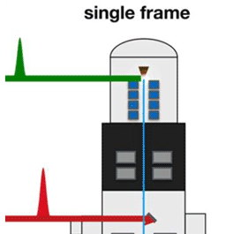
Figure 2: Laser-based TEM techniques (a) single-frame DTEM, (b) movie mode DTEM, and (c) laser-UTEM. Reprinted from [Reference Arbouet and Hawkes3], with permission from Elsevier.
Dynamic TEM (DTEM)
DTEM is also a high-speed imaging technique that uses a laser to create the electron pulse for imaging. However, as mentioned previously, DTEM employs longer and more intense UV laser pulses to create electron pulses capable of generating a satisfactory image with a single pulse. Therefore, DTEM is the only ultrafast technique that can image irreversible processes because it can generate an image nearly instantaneously. In practice, longer laser pulses (5 nanoseconds to 1 microsecond), larger photocathodes (800 μm diameter), and larger, more intense, deeper UV laser pulses (~1 mJ from 5ω over 50–100 μm spot sizes) are employed to generate > 106 electrons/pulse. The resultant electron beam typically loses some coherence due to the larger laser spot size creating an extended source. Additionally, space charge effects or even cathode depletion can cause the electron pulse to spread out in time. Therefore, the typical spatio-temporal resolution is in the tens of nanometers and tens of nanoseconds (~10-16 m⋅s) regime.
Pictorial representations of DTEM and laser-UTEM are shown in Figure 2, showing both the pump laser (red) to excite the sample and the probe laser (green) to generate the photoelectron pulse for the sample image. In single-frame DTEM (Figure 2a), a single probe pulse is provided any time after the pump pulse to capture the sample response at a specific time. For a time-lapse view of the irreversible process, movie mode (Figure 2b) is enabled by a burst of probe pulses and a synced downstream beam deflector that directs each pulse on to a separate portion of the imaging camera. Thus, images from each probe pulse are quickly recorded throughout the (irreversible) process evolution. Full control over time spacing between laser pulses allows probe pulse trains to be tailored temporally to best interrogate the intrinsic process response time.
In Figure 2c, a typical laser-UTEM stroboscopic setup is shown for a reversible process; probe pulses (green) are consistently synced with the pump pulses (red), and many probe pulses are collected to create the final image. Again, the reversible process must have a time period shorter than the pump laser repetition rate.
The first DTEM was demonstrated [Reference Bostanjoglo9] during the 1980s and was developed [Reference Dömer and Bostanjoglo10] through 2003, although the resolution was only slightly better than optical imaging. Researchers at Lawrence Livermore National Laboratory (LLNL) continued to improve [Reference King11] on these developments, achieving 10–20 nm resolution [Reference Armstrong12] with multi-frame movie acquisitions [Reference Santala13] and showing further improvements are possible through aberration-corrected [Reference LaGrange14,Reference Reed15] images. Examples of these DTEM capabilities are shown in the following applications.
Movie mode acquisitions have been used to extensively study the rapid solidification of Al-Si alloys developed for additive manufacturing [Reference McKeown16,Reference Roehling17]. DTEM captured the multiple growth domains of α-Al and coupled eutectic growth in real time after being melted with a Nd:YAG laser pulse (15 ns, 1064 nm, 2 μJ). The DTEM image shown in Figure 3 represents three separate tests (a, b, and c) of an Al-Si sample exhibiting different mechanisms along the direction of solidification (white arrow): (a) mixed regions formed within 10 microseconds of the heating pulse, bounding a liquid-solid interface (between the black and white dotted lines); (b) nucleation and growth of larger grains at 20.00 μs with a transition to planar/columnar growth between 25.55 and 30.65 μs; and finally (c) fully planar crystal growth after 32.55 μs. The identification of these complex dynamics during solidification in Al-Si alloys were previously unobserved and can be critical in modeling the rapid solidification process in Al-Si additive manufacturing materials.

Figure 3: Rapid solidification of Al-Si alloy captured via DTEM. Scale bars are 5 μm. See text for explanation. Reprinted from [Reference Roehling17], with permission from Elsevier.
Another example of the unique capability exclusive to the DTEM technique is the complexity of chemical processes when nanoparticle precursors are used, specifically, the phase changes required for the nanothermite reaction process [Reference Egan18] of Al/CuO nanoparticles when heated at 1011 K/s by a Nd:YAG laser pulse (12 ns, 532 nm, < 1 μJ). In Figure 4, the high-resolution initial and final state images allow the lower-resolution movie mode images to capture the evolution of the nanoparticle reaction Al + CuO → AlOx + AlyCuz + Cu. Changes in the Al/CuO aggregates are initiated within 45 ns of the laser pulse with the CuO nanostructures melting first (spheres in 330 ns image). The Al nanoparticles coalesce (central structure, 520 ns image) and then finally form phase-separated AlOx/AlyCuz spheroids. These observed morphology changes limited the reaction's heat-transfer rather than the reaction being limited by mass-transfer as seen in macroscopic systems, due to the much stronger absorption of the 532 nm radiation by the CuO nanoparticles.

Figure 4: DTEM movie mode representation of the formation of AlOx and Aly-Cuz nanoparticles from Al and CuO after being heated by a 532 nm laser pulse. Times listed in lower images are elapsed time after laser pulse, showing the roughly 1 μs reaction of Al + CuO → AlOx + Aly-Cuz + Cu. Reprinted from [Reference Egan18], with permission from the American Chemical Society.
RF (Laser-Free) UTEM
Until recently, laser-UTEM was the only method available to achieve ps time resolution in TEM imaging. In the past few years, laser-free UTEM has been developed, alleviating the laser requirements by employing radiofrequency (RF) modulation of the TEM's source beam. High-frequency (GHz) beam pulses have been demonstrated using a resonant deflecting cavity [Reference Qiu19–Reference Kisielowski21] and a traveling wave stripline [Reference Lau6,Reference Jing22] design. The resonant deflecting cavity is a fixed frequency RF device, thereby fixing the beam modulation rate. Typically, the cavity is filled with a dielectric material for compactness, and the unit is water-cooled to maintain the cavity's resonant frequency. When RF is applied at the resonant frequency, the electron beam traveling through the structure is deflected from the beam axis and becomes blocked by a chopping aperture. Thus, only electron trajectories with near-zero deflection can pass the aperture; for a sinusoidal field this occurs at each zero-crossing point, that is, twice per RF period. The traveling wave stripline uses the same type of aperture but has two phase-controlled RF inputs to create a well-defined transverse electric field. The field propagates through a slow wave structure that is phase-matched to the electron beam velocity. Thus, each beam electron sees a virtually constant electrostatic field as it propagates, and therefore the native beam properties are minimally perturbed, and the deflection is maximized for the RF cavity size. The RF is widely tunable, although the beam energy is fixed by the slow wave structure. These two approaches are compared in more detail in the Summary section, although they both require no modification to the electron gun and basically preserve the peak brightness and energy spread to the native source.
The traveling wave stripline design was incorporated in the commercially available [23–Reference Lyman25] Ultrafast Pulser (UFPTM) and has demonstrated straightforward implementation with excellent long-term stability. Figure 5 illustrates the UFPTM basic design and integration just below the native TEM electron gun. As shown in the inset, two traveling wave stripline “kickers” (K1, K2) are used with a beam-limiting aperture between them. The first kicker (K1) sweeps the beam across an aperture by imparting a small sinusoidal transverse momentum to the beam. The second kicker (K2) operates to remove the transverse momentum imparted by K1 to maintain the original beam axis. The RF driving signals to the kickers have variable phase and amplitude to optimize beam condition and enable custom beam configurations [22 – Figures 6 and 7]. An RF pump/probe arrangement [Reference Lau6,Reference Fu26] is also shown in Figure 5: since two electron probe pulses are created in each RF cycle (one for each zero-crossing point), a frequency doubler has been added to bring the pump rate equal to the probe rate. The phase delay enables probing of the sample's response throughout the RF cycle.
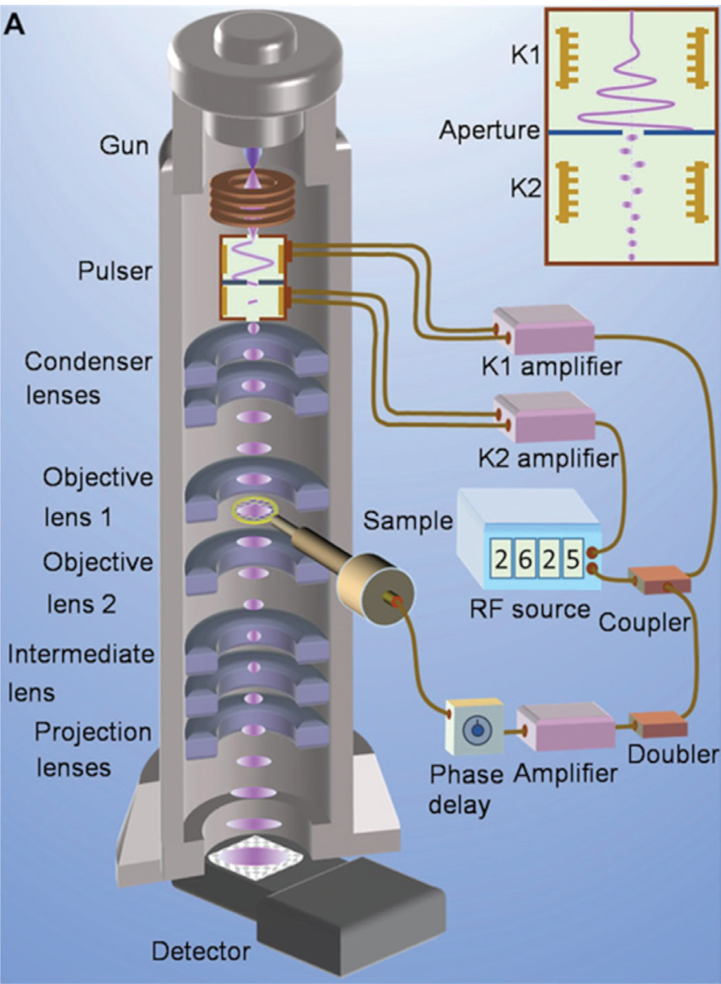
Figure 5: Ultrafast Pulser (UFPTM) integration into TEM. UFPTM main column elements: kicker (K1, K2) and aperture shown in inset. Reprinted from [Reference Fu26], with permission from American Association for the Advancement of Science.

Figure 6: Brightfield image and diffraction images comparing imaging capabilities of UFPTM (pulsed) and native instrument (continuous). Native instrument is JEOL JEM-2100F, UFPTM repetition rate of 2.6 GHz. Courtesy of Dr. Spencer Reisbick, Brookhaven National Laboratory.

Figure 7: Diffraction fading curves for paraffin and purple membrane materials using continuous and UFPTM modulated electron beam at 20% duty factor. Native instrument is JEOL JEM-3010. Courtesy of Dr. Hyeokmin Choe (Euclid Techlabs), Dr. June Lau (NIST-Gaithersburg), and Dr. Yimei Zhu (Brookhaven National Laboratory).
As there is no laser driving the pulsed beam emission, the RF design dictates the electron pulse repetition rate in the RF UTEM designs. For the UFPTM, the native practical operating frequency is 500 MHz up to 10 GHz with pulse picking techniques employed to reach down to sub-Hz frequencies. For the resonant deflection cavity design, the resonant frequency is fixed, typically in the 1–10 GHz range, but has been operated as low as 75 MHz using a dual-mode resonator [Reference van Rens27].
With the introduction of the newer RF UTEM technology, there has been significant work on the resultant beam characteristics and ultimate spatio-temporal resolution capabilities. Since these methods employ the original electron gun installed in the electron microscope, the pulsed beam is naturally closer to the native TEM beam character compared to a laser-driven beam with a modified cathode and gun. In practice, the UFPTM capabilities have been shown to be nearly identical to the native electron beam, losing negligible coherence when enabled. Excellent spatial resolution was achieved as the continuous and pulsed beam are almost indistinguishable for the gold nanoparticle images shown in Figure 6. The brightfield images (Figures 6a and 6b) have indistinguishable resolution between the native (continuous) and pulsed beam. Similarly, the ultrafast diffraction image (Figure 6c) is indistinguishable from the continuous beam image. Pulsed images in Figure 6 were acquired using a 2.6 GHz pulse train, resulting in a pulse duration of ~3 ps (~1 e-/pulse). Details of the TEM are given in the caption.
For samples sensitive to high beam energies, the wide repetition range of the UFPTM has been shown to extend and predict the onset of radiation damage at various ultrafast imaging conditions. Figure 7 contains the changes in the diffraction fading curves for paraffin (C36H74) and purple membrane (a plasma membrane of Halobacterium halobium), as the continuous electron beam is modulated using the UFPTM [Reference Choe28,Reference Choe29]. At 20% duty factor the accumulated dose was nearly doubled at the 1/e point, confirming the dose rate dependence versus a total fluence dependence on the lattice structure. This is an intriguing capability for biological samples, providing a route to reduce beam-induced damage at room temperature. Furthermore, due to the GHz-level frequencies of the RF UTEM techniques, these stroboscopic studies can be completed in a small fraction of the time of the complementary laser-UTEM technique.
Summary
While most of this article has been focused on the introduction and application of the various UTEM techniques available, this section will summarize the capabilities of the techniques and address some of the pertinent implementation details for each of them. Table 1 lists the four UTEM techniques discussed and compares key characteristics of beam operation, sample excitation and overall performance.
Table 1: Comparison of present-day UTEM techniques. ✓ = available/demonstrated, ✓* = possible, with extensive time delay, ✓‡ = possible/not demonstrated, ✓^ = possible under special circumstances.

For the operation modes, DTEM is only a single-shot technique that can be extended into the powerful movie mode, whereas a stroboscopic or single-electron regime is achievable with the other three techniques. For the RF UTEM techniques, the microscope may be operated in a continuous or native mode simply by turning off the RF; in a matter of seconds the microscope can be switched from ultrafast modulation to continuous. For a microscope employing laser-UTEM it can take a bit longer, as the photocathode must, at a minimum, be heated or the applied field ramped to convert it back to a thermionic or a field emission beam source. In a typical case not requiring a vacuum vent, up to an hour may be needed for the source temperature to stabilize, and, of course, the beam characteristics (current density, energy spread, divergence, etc.) will be changed relative to pulsed operation.
Although not extensively demonstrated in the literature, the sample excitation for pump-probe experiments is widely possible across all four instruments. Sub-ps triggering and timing techniques are well known, and researchers have combined various sample excitation methods with all beam modulation methods. A key parameter to consider is the maximum probe repetition rate, as it defines how long an acquisition time is needed to obtain a clear image for a reversible process. The response and recovery times of the system ultimately determine the maximum usable probe rate with a given sample, thus for characterizing a wide range of processes (that is, UTEM as a shared resource for a diverse community), an adjustable probe rate would be ideal. System repetition rates are easily adjustable for laser or UFPTM, although limited by the maximum laser repetition (100 kHz, typical) rate for laser-UTEM and the maximum RF frequency for RF-UTEM (12 GHz, typical).
In terms of performance, laser-UTEM can achieve atomic resolution, sub-eV energy spread, and high coherence when using the best nano-photoemitters but suffers when using larger photo-thermionic cathodes. For RF UTEM, atomic resolution has not been fully demonstrated in the literature, although it is expected. A caveat for the RF UTEM techniques discussed is that while the RF frequency is fixed for the RF resonator design, it is compatible with any beam energy. Due to the phase-match requirement between the incident electron velocity and the propagation of the traveling wave in the UFPTM design, the beam energy for its RF traveling wave design is essentially fixed, although the repetition rate is widely variable.
Commercial availability has improved as these techniques are being adopted across multidisciplinary fields. The initial laser-based techniques that had been typically only laboratory-built research tools have become commercially available [30] as well as the RF-based UFPTM that can be retrofitted to electron microscopes by all manufacturers.
Conclusion
As TEMs have been adopted by diverse communities in multidisciplinary fields, additional EM markets have grown, and TEMs have become the standard in high-resolution imaging. Complementary techniques have developed for a broad range of ultrafast spatio-temporal imaging (10-15 to 10-23 m⋅s). While the process details play a role in identifying the ideal ultrafast approach, these lines continue to be blurred as sample excitation/pump methods expand and the techniques mature. Hybrid pump-probe approaches are likely to accelerate the adoption of ultrafast techniques, as users identify key performance requirements and avoid needless complexities. The intention of this article is to supply new adopters with unbiased information to make informed choices as they progress along their individual research paths.
Additional references on UTEM techniques related to this article and a webinar-based presentation of the materials can be found at https://www.euclidtechlabs.com/supplementary-utem-refs.
Acknowledgements
The authors (EM and DL) acknowledge support from NIH SBIR Phase 2 (1R43GM133267-01) and the US Department of Energy (DOE) Basic Energy Sciences SBIR Phase 2a (DE-SC0013121). They also thank Dr. Spencer Reisbick (Brookhaven National Lab) for the unpublished images in Figure 4. This work was performed in part (support of JR) under the auspices of the U.S. Department of Energy by Lawrence Livermore National Laboratory under Contract DE-AC52-07NA27344.


