


Two recent articles in Microscopy Today describe methods that purport to produce three-dimensional (3D) information from single SEM images [Reference Mignot1][Reference Sturm2]. They are bogus. These authors are not the first to claim to get 3D information from SEM images without tilting the sample [Reference Zurek3]. Nor is this the first time that attention has been drawn to the errors of such methods [Reference Woodhouse and Eades4].
The article by Robert Sturm (“Stereoscopic Effects from Single SEM Images,” Microscopy Today 26(4) (2018) 34-37) is the more plausible of the two. However, Sturm says, “It is commonly assumed that parts of an object nearer to the viewer are brighter in appearance, whereas parts of the object at a greater distance from the viewer are darker.” Well it was (with equal validity) commonly assumed that the earth is flat. The assumption that brightness correlates with height is false and is a faulty basis for the method proposed. Those who have worked in scanning electron microscopy know that the brightness at a location in an image depends greatly on the composition at that position, on the local shape of the specimen, and whether there is shading from other parts of the sample. The contrast in the image depends next to nothing on the changes in the height of the specimen.
So it is not surprising that the stereo images used by Sturm to illustrate his method show shapes that are clearly very different from the actual shapes of the objects. Stereoscopic effects may be produced by Sturm’s method, but they are not related to the true shapes of the sample.
In summary: Do not use Sturm’s method; or if you do, do not expect that the shapes you see in the stereo images will have any connection with the real shapes of the objects.
The article by Christophe Mignot, (“Color (and 3D) for Scanning Electron Microscopy,” Microscopy Today 26(3) (2018) 12-17) is mainly concerned with coloring images so information that is clear to the microscopist may be better communicated to a non-expert. I have no quarrel with that. But two sections of the article are concerned with 3D imaging. The first of these sections describes how it is possible to get qualitative 3D information in the following situation: you have a four-quadrant backscatter electron detector, acquire separate images from each of the four quadrants, and run the images through an elaborate computing process. Moreover, the sample needs to be of uniform composition, smooth, nearly flat, and with no re-entrant regions. Surely it would be easier to tilt the sample and take a stereo pair.
The second section on 3D images is just laughable. Mignot says, “… algorithms can produce a credible 3D color model from a single SEM image.” To illustrate this he puts an original SEM image through a complex computing process, but the results he gives are very far from credible. Much information in the original image is lost and much spurious information is added. In Mignot’s article, Figures 7, 8, and 9 illustrate his claims. They all show 3D effects, but it is clear that these 3D effects do not reflect the real shapes of the specimens. This is especially clear in Figure 8.
Conclusion: Nearly all scanning electron microscopes allow the sample to be tilted. It is easy and quick to take stereo pairs that give good 3D images. I beg of you, please get into the habit of taking stereo pairs of your samples and ignore these complex computer methods, which give false information.
Author Response
Contrary to Alwyn Eades, I am thoroughly convinced that the method is not bogus at all because stereoscopic effects become clearly visible. Most SEM images of objects where the object is bright against a dark background contain the appropriate light-dark information, but some do not. Certainly, the surface rendering process executed by the computer program bears some inaccuracies. On the other hand, object depth mapping based on a light-dark gradient represents an appropriate tool for the extraction of 3D information. Generation of a perfect gradient with decreasing brightness from foreground to background is rather difficult due to shading effects. Mounting of the object on a sample holder with low electron-reflection can efficiently support this task. Summing up, I strictly contradict Alwyn Eades and recommend the use of the method described in my article. Take your old SEM images and try the program.
Author Response
I would like to thank Alwyn Eades for his feedback concerning my recent article including a section on 3D reconstruction in SEM, and I welcome the opportunity to address the issues raised.
In all instances, stereo reconstruction, using two images acquired with different tilts of the specimen, remains the most metrologically accurate method for obtaining height values in the SEM. There is no debate on this point, and the MountainsMap® SEM software mentioned in the article is one of several commercial programs that can extract reliable height information from a stereo pair.
Definitions. Before addressing Prof. Eades’s points, I should describe some definitions I use. I believe the term “stereo” should only cover vision from two different angles (as human vision does). Stereo uses the concept of “shape from motion”: it observes how much a given point on the object moves between two views and then calculates the third dimension from that motion.
Shape from shading obtained from a four-quadrant detector does not produce stereo, as in the stereo-pair images described above, but rather a 3D effect that can be measured and calibrated. Shape from shading observes the illumination of the surface, and interprets such illumination as a slope, then integrates the slope into heights; (in terms of mathematics and functions, slope is the derivative of height, so conversely height is the integral of slope). Most manufacturers use four detectors, but the principle of shape-from-shading can apply to any number of detectors, with a minimum of three. All detectors see absolutely the same scene simultaneously—there is no motion.
In no instance would I designate as “stereo” any type of shape from shading. Stereo and shape from shading are two different things; they only share the quest for 3D.
Concern 1. Prof. Eades raises a first concern about shape from shading principles, that is, the ability, using a four-quadrant detector, to assess heights in a single operation without tilting the sample. In particular, Eades’s comment that it would be “easier to tilt the specimen” to take a stereo pair than to acquire images with a four-quadrant detector appears to be, in large part, a matter of personal taste. The four-quadrant method has its own advantages:
(a) No tilting involved. The four images are done simultaneously in a single shot, which is easier and quicker; there are situations where it is impractical to tilt the specimen, such as in the inspection of large semiconductor wafers. Manufacturers such as Hitachi or JEOL offer four-quadrant detectors and MountainsMap® SEM software along with calibration procedures dedicated to their own instruments in order to get the best out of this method.
(b) Differentiating a hole from an inclusion. Four-quadrant detectors have two pairs of opposite detectors to get a differential signal for each orthogonal direction. When the surface is intrinsically less reflective, signals from opposing detectors would decrease simultaneously (an inclusion); whereas, in the case of a slope, they would deliver opposite signals (a hole). It can be useful to use a 3D image as opposed to a single view to differentiate holes and dark material inclusions (see Figure 1).
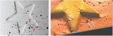
Figure 1 Left: BSE image of a Euro coin detail. Black spots are visible, but it is difficult to differentiate material inclusions from cavities. Right: The use of all channels of the four-quadrant detector brings extra information allowing the construction of a 3D model clearly showing the differences between material outcrops (blue arrows) and cavities (red arrows).
There are limitations to the four-quadrant method. It may not give the full height if high slopes are involved, or at least the height will be locally wrong. Also, the method will not perform well for overhangs and re-entrant regions (a limitation shared with the stereo method since a height can be calculated only if the area is visible from both view angles).
Concern 2. Prof. Eades’s second concern was about obtaining 3D effects from single micrographs using the principles described in my article. Four-quadrant reconstruction (using four images made at the same time) and single-image reconstruction have different purposes and claims and should not be confused.
Eades disputes the idea of using gray level as height, assuming this to be an illegitimate assertion. Indeed, even if hollows on a textured object often appear darker, the gray level of SEM micrographs is only poorly correlated to the height. Using gray level as the height is not the method described and illustrated in my article. Inside the SEM, areas at the surface of specimen can be bright for several reasons. The signal collected by the electron detector is typically a mixture of secondary electron (SE) and backscattered electron (BSE) signals that may be dependent on some or all of the following: the location of the electron detector, SEs and BSEs escaping the surface as a function of tilt angle, SEs escaping from both the top and bottom of sharp edges, and BSEs escaping the surface as a function of the specimen composition.
As far as single-image reconstruction is concerned, my article investigates specific cases where we can build a 3D effect (not a metrologically accurate model). Thus, I wrote, “Putting the accuracy of height values aside, however, image reconstruction can provide a useful 3D effect” from a single SEM image. MountainsMap SEM® software uses less trivial principles than just the raw gray level to create a 3D effect from a single image:
(a) Downgraded shape from shading method. In the case of a homogeneous single-phase material and oblique “lighting,” the software uses the four-quadrant “shape from shading” algorithm, but downgraded to use a single image (instead of four, one per quadrant) and a single direction (instead of two orthogonal directions). The requirement of a single-phase material is due to the lack of a differential signal specific to the single-image case, a restriction that does not apply to the four-quadrant 3D reconstruction as discussed above. In single-image reconstruction, the gray level is correlated to the slope in a single direction, and this slope is integrated into heights; as there is only one direction, the height is incomplete and cannot be calibrated but may however be sufficient for rendering purposes. Figure 7 of my article illustrates this principle. I purposely chose an image that has inconsistent illumination (left side is much darker) to show the ability of the software to be able to correct this defect within the operation.
(b) Shape from object contours. In the case of multiple objects, detection of object contours is used to attribute some shape to the object. For instance, one can understand that in the case of a sphere, height can be assessed using its diameter. Figure 8 of my article illustrates this principle. The generated 3D effect (which used only the upper three quarters of the image to avoid the scale bar) looks glossy because of the rendering mode chosen; again, it probably does not show the full height, but at least the heights shown are correlated to those expected.
Thus, in the case of single-image 3D reconstruction as in Figures 7 and 8 of my article, the subject is 3D rendering and not calculating accurate Z heights.
In conclusion, stereo imaging by tilting the sample is indeed the best choice for obtaining height values. The four-quadrant method has been shown to be reliable for 3D imaging without tilting, but it has some limitations that must be understood. In certain specific cases, a single image can produce interesting 3D effects only for rendering purposes and without quantitative height information.
