


Introduction
Along with moves to decrease CO2 emissions worldwide, research into methods of improving the performance of rechargeable electric batteries is growing quickly. Along with other research tools, TEM using a microscope with full analytical facilities is a powerful tool for studying chemical changes in relation to microstructure at high resolution. The results presented here arose from studies of the electrochemical behavior of experimental positive nickel electrodes, in which the active mass was nickel hydroxide (Ni(OH)2) powder [Reference Martineau and Wronski1].
In spectra obtained using electron energy-loss spectroscopy (EELS), the near-edge structure (ELNES) of the oxygen K (O K) edge is sensitive to the electronic environment of the oxygen ions, leading us to use this technique to examine chemical changes that occur in the electrode as a result of charge-discharge cycling. However, a critical stage in achieving such a goal is the preparation of very thin specimens, avoiding major changes in the chemistry of the constituents.
Here, we summarize the specimen preparation technique used and some results of TEM examination, in order to point to future applications of these techniques, for example, to assess chemical and microstructural changes for the origin of “fading” in cycled batteries. “Fading” is an irreversible loss of the nominal utilization of the electrochemically active mass in an electrode [Reference Martineau and Wronski1].
Experimental Techniques
The positive Ni electrode used for this study was prepared using Ni(OH)2 powder (doped with Co(OH)2), which was wet pasted into nickel metal foam, then dried and calendered to yield a thin electrode strip, which was paired with a negative hydride electrode to form a NiMH cell. The electrode was then subjected to multiple electrochemical charge-discharge cycling, leading to “fading.” Samples were examined in the charged state, being wet from the residual aqueous electrolyte of 6M KOH doped with lithium hydroxide LiOH [Reference Carpenter and Wronski2]. The preparation method for the electrode is particularly critical if its integrity and chemistry is to be preserved. Drying out the electrode before embedding results in cracking and the possibility that chemical changes might occur. The electrode was, therefore, embedded without ever having been dried out by using an embedding technique pioneered for life science applications [Reference Carpenter and Wronski2,Reference Glauert and Lewis3].
The first stage involved gradual replacement of the electrolyte with distilled water using a flow-through technique (Figure 1). This was followed by dehydration, beginning with a solution of 50% ethanol in water, followed by a 75% solution, and finally anhydrous ethanol. An acrylic resin, typified by LR White, has the advantage of low viscosity and compatibility with ethanol, so the final embedding was again done in stages starting with 50% resin in alcohol and gradually increasing the resin concentration to 100% [Reference Carpenter and Wronski2]. The individual stages were usually repeated twice. A useful guide was that the volume of liquid for each stage was approximately 20–50 times that of the electrode.

Figure 1: Illustrating the principle of the flow-through method for replacing electrolyte with the embedding medium [Reference Carpenter and Wronski2]. Reprinted with permission from Cambridge University Press.
Cutting thin sections in life sciences is normally accomplished using an ultramicrotome, but early experiments with embedded electrodes were unsuccessful because of the major differences in hardness of the components in such a complex composite. In contrast, the application of the focused ion beam (FIB) method at Fibics Inc. (Ottawa, Ontario, Canada) [Reference Phaneuf, Giannuzzi and Stevie4,Reference Phaneuf5] led to instant success, producing a relatively robust specimen with areas that were thin enough for analysis in the TEM using EELS.
The FIB-processed specimen was then examined in an FEI Titan3 80-300 TEM operated at 300 keV, equipped with a CEOS aberration corrector for the probe forming lens and a monochromated field-emission gun. Annular dark-field (ADF) images were collected using a high-angle ADF (HAADF) Fischione detector in scanning transmission electron microscopy (STEM) mode. This technique provides image brightness related mainly to the atomic number (Z) and the thickness of the region analyzed. When combined with an aberration corrector, ADF-STEM can reach a sub-Angstrom resolution [Reference Couillard6] and single-atom sensitivity [Reference Couillard7]. The TEM instrument was also equipped with an energy-dispersive X-ray (EDX) spectrometer (EDAX Analyzer, DPP-II). The EELS analysis was performed on a Gatan Tridiem 866 Image Filter. EDX spectra were acquired with the specimen tilted at 15o to optimize the signal intensity.
In order to identify the phases present in the electrode using the near-edge structure of the ELNES, it was necessary to have reference spectra. For this, we had oxygen K-edge spectra for Ni(OH)2 and NiO from earlier work [Reference Carpenter and Wronski2], reproduced here in Figure 1. We do not show or discuss here the Ni L2,3 spectra we collected, because the resolution was insufficient to distinguish between the possible nickel phases. Also, low-loss EELS spectra showing collective excitation of valence electrons known as plasmons are omitted from this report. In some spectra, we did observe a small shift between 22.7 eV and 22.5 eV for the bulk plasmon, and a more pronounced change from 6.15 eV to 5.6 eV for the lower-energy plasmon (more conductive, near-surface origin), but there was too much uncertainty because of the peak broadness. Also, there are few data for comparison of low-loss spectra in the published literature.
Results
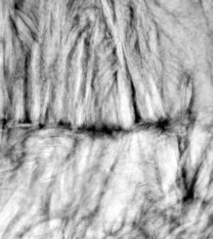
Figure 3 shows a low-magnification ADF image obtained from the embedded electrode in STEM mode. The image shows a rounded single micro-grain of Ni(OH)2 within the electrochemically active mass of the electrode. Part of another micro-grain is present at the bottom of the figure. Note that because this is a dark-field image [Reference Couillard6], the light area on the right corresponds to a thicker region of the Ni foam within which the active hydroxide phase was contained. At a higher magnification (Figure 4a), the individual plate-like crystals within the spherical particles of the hydroxide phase can be seen to be almost intact. Nanometric porosity between the crystallites can be seen propagating radially. This nanoporosity provides paths required for efficient access of the electrolyte ions that are exchanged in the oxidation-reduction (redox) process. Specimen preparation in the FIB resulted in a large enough area of the active mass that was thin enough for studying chemical changes using ELNES spectra from the O K edge.

Figure 2: Standard EELS spectra for NiO and Ni(OH)2, [Reference Carpenter and Wronski2]. Reprinted with permission of Cambridge University Press.

Figure 3: ADF-STEM image showing an area from the electrode, prepared using FIB sputtering.

Figure 4: (a) ADF-STEM image at higher magnification showing that the Ni(OH)2 particle is composed of nanometer-scale crystallites (previously shown to be in the form of platelets) [Reference Carpenter and Wronski2], (b) typical EELS spectrum from the majority phase in thin areas such as shown in Figure 4a.
Figure 4b shows the O K edge in an EELS spectrum that was taken with a focused beam from a thin area of the active mass of the electrode that was formally Ni(OH)2. This spectrum was typical of nearly all of the active mass in the charged condition. Comparison with the standard spectra of Figure 2 revealed that most of the active material no longer showed a spectrum corresponding to either Ni(OH)2 or to the NiO phase on a more macroscopic scale.
Multiple EELS spectra were also obtained from line scans stepped across several regions near the edge of an active mass particle (Figure 5a). Individual spectra contained significant noise, so groups of 5 spectra from points along each scan were summed. Close inspection of all the spectra from the line scans showed that the majority exhibited the same spectra as the dominant phase shown in Figure 4b. Figure 5b shows four selected spectra from the positions indicated on the line scan. Of these, spectra numbered 2 and 4 contained fine structure characteristic of the major phase. In contrast, spectra numbered 1 and 3 revealed the presence of local regions of unchanged Ni(OH)2. No evidence for the EELS spectra characteristic of the presence of NiO in the microstructure was observed.

Figure 5: (a) Line-scan from which multiple EELS spectra were obtained, (b) EELS spectra from 4 locations along the line scan; the identities of the corresponding phases are discussed in the text.
Discussion
The charge/discharge reactions that occurred in the positive Ni(OH)2 electrode can be found using the well-established Bode diagram discussed in many publications [Reference Wronski8] and described by equations 1 and 2:


where the forward and reverse arrows, respectively, denote discharge and charge of the electrochemically cycled active mass. Equation (1) applies to an electrode that is still in good working condition, that is, it does not exhibit any substantial drop in charge capacity that is characteristic of an aging electrode. Equation (2) becomes gradually more important when the electrode has been subjected to many charge/discharge cycles. The β-type phases, when charged to nickel oxy-hydroxide (NiOOH) or discharged back to the hydroxide (Ni(OH)2), are well-ordered crystal structures, while the respective α- and γ-phases exhibit increased degrees of structural disorder in stacking of the oxy-hydroxide layers [Reference Wronski8,Reference Wronski9,Reference Casas-Cabanas10]. After multiple charge-discharge cycles, conversion back to the preferred β-Ni(OH)2 phase becomes incomplete as the alternative α-Ni(OH)2 phase accumulates in the active mass of the electrode. This is one reason for the lost discharge capacity of the positive electrode and effectiveness in rechargeable NKH batteries. Since there is little change in chemical environment around the oxygen atoms in either Ni(OH)2 or NiOOH, as these phases change their layer's structure between β, α, and γ, the respective changes in ELNES of the O K edges are expected to be very subtle.
However, it is well established that for an electrode in the charged condition, the oxy-hydroxide phase constitutes the majority of the active mass. It is, therefore, concluded that the spectrum from the dominant phase, with its additional peak extending from 525 eV to 530 eV (Figure 4b), corresponds to the NiOOH phase. In the case of the line scan of Figure 5, an extra peak in the same position, characteristic of what we conclude to be NiOOH, was seen in the majority of the spectra, typified by numbers 2 and 4 in Figure 5b. Typical exceptions occurred for a small number of spectra in the line scan, such as those numbered 1 and 3. These latter spectra were easily seen by comparison with the standard spectra of Figure 1 to be characteristic of Ni(OH)2. It should be noted that an extra peak is also present in the ELNES spectrum for NiO, but it occurs at a different energy from that for the dominant phase, NiOOH.
EDX spectra revealed that the active mass particles were sometimes separated by a phase that was rich in carbon, appearing dark in the ADF-STEM images (Figure 4a). This is most likely evidence for the presence of embedding resin used to replace the electrolyte prior to sectioning in the FIB. It was to be expected that there was sometimes a small gap between the Ni foam and the active mass, as well as between the active mass particles that became filled with resin during embedding. This was probably evidence of the macroscopic swelling that was reported to occur after multiple electrochemical cycling events [Reference Martineau and Wronski1].
Previous work [Reference Carpenter and Wronski2,Reference Wronski9,Reference Malis and Li11] has shown that there is a tendency for segregation of the doping element, Co, close to the surface of the Ni(OH)2 microspheres. However, although a low signal for Co could sometimes be discerned in the EELS or EDX spectra, it was not strong enough to enable any conclusions to be reached about whether there was a role played by Co in the phase transformations involved in charge/discharge cycling. Despite that, there is little doubt that high-resolution studies with long collection times could yield more details if it were desired to pursue this question further. Another avenue that would benefit from further investigation would be whether the nanometer-scale crystallites that comprise the active mass behave in a homogeneous manner or if the reactions are influenced by the surfaces of the nanocrystals, which would be expected to be chemically more active than the bulk.
Conclusions
The preparation of a thin specimen from an electrode in the charged condition, using embedding techniques from life science electron microscopy followed by thinning in a FIB apparatus, has been demonstrated. If embedding is carried out for an electrode in the charged condition without it being first dried, the phases produced by electrochemical cycling are preserved. We also demonstrated that EELS, using a TEM, is a powerful technique for studying the chemical changes responsible for the “fading” of the Ni positive electrode that takes place during multiple charge-discharge cycling in a NiMH battery and relate the chemical changes to microstructure. Another possible application would be to study the location and influence of doping elements in the active mass on a microscopic scale. The ELNES of the O K edge for NiOOH, shown here, has not been previously reported.
Acknowledgements
The study of this electrode would not have been possible without the help of Michael W. Phaneuf, CEO of Fibics Inc., whose expertise and generosity in making the FIB specimen is gratefully acknowledged. Electron microscopy was carried out at the National Research Council Canada, a facility that is part of the Energy, Mining and Environment Research Centre.


