


Introduction
Ultra-wideband (UWB) bandpass filter (BPF), as one of the key component in the UWB system, influences the overall system performance [Reference Wei, Wang, Yang and Shi1]. A number of UWB BPFs have been reported using different methods and structures: optimum short-circuited stubs [Reference Murmu, Koley, Bage and Das2], stepped impedance resonator (SIR) [Reference Borazjani, Nosrati and Daneshmand3], multiple-mode resonator (MMR) [Reference Chu, Wu and Tian4, Reference Shaman and Hong5], etc. However, coexisting wireless services in the UWB frequency spectrum may cause potential interferences, such as WiMAX (3.4–3.6 GHz), wireless local area network (WLAN) (5.15–5.35 and 5.725–5.825 GHz), C-band satellite communication services (CSCS) (6.425–6.725 GHz), X-band satellite communication services (XSCS) (downlink: 7.25–7.75 GHz, uplink: 7.9–8.395 GHz), ITU-8 band (8.3–9.1 GHz), and radio navigation (RN) band (9.3–10.6 GHz).
In order to effectively suppress interference of other coexisting wireless services in passband, multi notched-band UWB BPF has been widely concerned, among which the design of UWB BPF with triple-notched bands has made great progress [Reference Kumar, Gupta and Parihar6–Reference Chen and Ding10]. In [Reference Kumar, Gupta and Parihar6], a triple notched-band was created using a C-shaped and an E-shaped combined triangular ring loaded stub resonator with a high skirt selectivity of 0.975, of which the size is relatively large. Reference [Reference Kamma, Das, Bhatt and Mukherjee7] proposed triple notched bands with low insertion loss by loading two coupled multi-mode resonators (MMR1 and MMR2), however it has relatively low selectivity. Furthermore, researchers pay more attention on designing quadruple notched UWB BPF to increase the required notches [Reference Sung11–Reference Borhani, Honarvar and Virdee14]. Multiple notches (triple and quadruple) were created [Reference Nosrati and Daneshmand12] using the parallel integration of gap-coupled microstrip resonators and two tri-section stepped-impedance resonators, but the performance of out-of-band rejection and selectivity is poor. A quadruple notched-band was generated by eight arrow-shaped resonators [Reference Guo13], but the selectivity is poor. Reference [Reference Borhani, Honarvar and Virdee14] proposed a quadruple notched-band using MMR incorporated a parasitic coupled element [Reference Borhani, Honarvar and Virdee14], which can achieve high selectivity up to 0.955 (20 dB), but it has only quad notched band and the passband range is 3.1–10.71 GHz.
Nevertheless, it is challenging to design more notched bands filters while maintaining high selectivity and wide bandwidth. There were six fundamental fractal curves, namely, Cantor, Koch, Minkowski, Hilbert, Sierpinski and Peano. Hilbert fractal curve slit in particular is selected for its specific geometry and the highest compactness of final circuit dimension. In this paper, a quintuple notched-band UWB BPF with high selectivity (0.944) and wide bandwidth (2.94–11.05 GHz) is proposed. To produce quintuple notches, this filter adds a gap-coupled approximate closed-loop C-shaped stepped impedance resonator (ACLC-SIR) along with a L-shaped resonator and a Hilbert fractal curve slit [Reference Guo, Xu and Wang15]. The ACLC-SIR is used to construct triple notches (first, third, and forth notches). The L-shaped resonator and the Hilbert fractal curve slit are applied to obtain the second and fifth notched bands with higher degree of adjusting freedom, which has rarely been reported in the past.
Quintuple notched-band design and analysis
The structural layout of the proposed filter is shown in Fig. 1. MMR is the basis of designing quintuple notched bands UWB BPF. Five notch bands are implemented by loading three different units, i.e. an ACLC-SIR is located under the center of the plane, and the L-shaped resonator is loaded on interdigital-coupled feed lines along with a Hilbert fractal curve slit that is etched on the center plane of the stepped-impedance open stub.
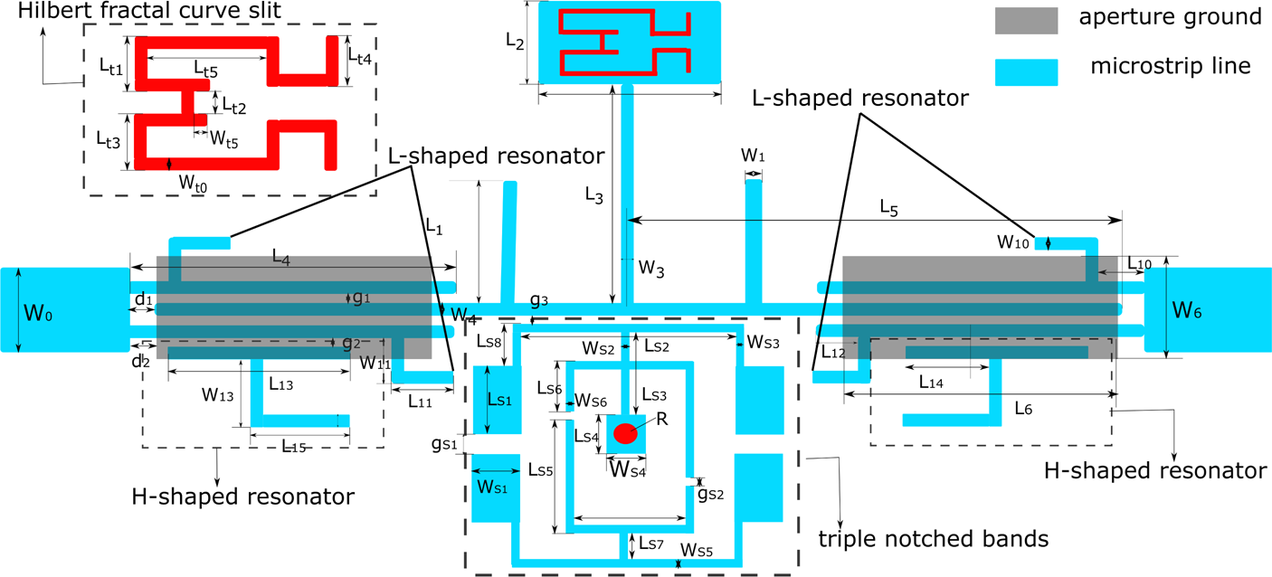
Fig. 1. Schematic of the proposed quintuple notched bands UWB filter.
Basic UWB BPF design
To obtain the proposed quintuple notched-band filter, a common MMR loading open stub is adopted [Reference Chu, Wu and Tian4]. The MMR consists of three open stubs (one stepped-impedance stub at the center and two uniform-impedance stubs at the symmetrical sides). Interdigital-coupled feed lines and two rectangular aperture-backed structures provide tight coupling. Since the MMR is symmetrical in structure, the odd- and even-mode methods were used. The equivalent circuit of odd- and even-mode can be expressed as follows:


From the resonance condition Yin,odd = 0 and Yin,even = 0, the resonate modes of odd-mode and even-mode are determined by the respective equation:


It can be seen from solutions (5) and (6) that the odd-mode resonance of the MMR depends on two uniform-impedance stubs (L 1,W 1) and even-odd resonance could be controlled by the stepped-impedance stub of widths (W 4,W 5) and lengths (L 4,L 5). The simulation of the basic UWB filter is shown in Fig. 2(c). It can be seen that the MMR has five modes (two odd-modes: f o1, f o2. three even-modes: f e1, f e2, f e3.) within the passband under weak coupling. The passband covers from 2.89 to 11.93 GHz, and two transmission zeros are located at 2.58 and 12.38 GHz at the lower and upper band to enhance the filter's selectivity.

Fig. 2. Simulated |S 21| of basic UWB BPF. (a) Layout of the basic UWB BPF. (b) Odd- and even-mode equivalent circuit. (c) Simulated |S 21| of the basic UWB BPF. Associated parameters: L 1 = 3.6, L 2 = 3.68, L 3 = 9.1, L 4 = 7.81, L 5 = 11.1, W 0 = 2.6, W 1 = 0.5, W 2 = 4.4, W 3 = 0.4, g 1 = 0.12, d 1 = 0.21, L 6 = 6.4, W 6 = 2.4, d 2 = 0.72 (all in millimeters).
Quintuple notched-band design
Triple notched bands are - implemented in the UWB BPF by introducing an ACLC-SIR. ACLC-SIR is located under MMR, among which is a symmetry C-shaped resonator. It consists of two half-wavelength SIRs and two short-circuit stubs. The transfer characteristics of the proposed ACLC-SIR are shown in Fig. 3. It can be seen from Fig. 3(a) that as L s6 goes from 1.1 to 1.7 mm, first resonance frequency remains unchanged, second resonance frequency decreases from 7.68 to 7.26 GHz, and third resonance frequency changes slightly. Figure 3(b) shows the change of resonance frequency with L s1. When L s1 increases from 2.3 to 2.6 mm, first resonance frequency remains unchanged, second notched band resonance frequency increases from 7.25 to 7.51 GHz, and third notched band resonance frequency slightly changes in a smaller range. From Fig. 3(c), along with W s1 increase from 1.1 to 1.4 mm, three notched frequencies decline from 5.46 to 5.09, 7.84 to 7, and 9.14 to 8.61 GHz, respectively. The 3 dB bandwidth (BW) is mainly controlled by gap-coupled between ACLC-SIR and UWB filter (g 3). Figure 4(a) shows the resonance frequency and the BW with slit g 3. When g 3 is from 0.1 to 0.3 mm, the first notched band slightly changed, while its BW decreases from 350 to 170 MHz. The second resonance frequency decreases from 7.59 to 6.98 GHz, and the BW decreases from 380 to 210 MHz. The third notched band decreases from 9.04 to 8.68 GHz, and the BW has changed a lot (from 920 to 350 MHz). The coupling of two symmetry C-shaped (g s1) and two short-circuit stubs (g s2) affects the center of notched bands in Fig. 4(b). As g s1 and g s2 gradually increase, the third notched band decreases from 8.91 to 8.67 GHz. The second notched band increases from 7.33 to 7.81 GHz. The first notched band slightly changed. Its BW remains unchanged. Therefore, by appropriately adjusting the above resonator, a triple notched band could be achieved with high degree of freedom at desired frequencies.

Fig. 3. Parametric analysis of the structure for different parameters: (a) L s6, (b) L s1, (c) W s1.

Fig. 4. Parametric analysis of the structure for different parameters: (a) g 3, (b) g s1, g s2.
A single notched-band in the UWB BPF is implemented by introducing symmetrical structure in the interdigital-coupled feed lines. This is achieved by loading four L-shaped resonators symmetrically on both sides. The notched band is centered at around 6.57 GHz to prevent interference from C-band communication satellite. Figure 5 shows the effects of L 11and W 11 on determining the center frequency. In Fig. 5, L 11 increases slightly from 0.4 to 1.0 mm, the center frequency of the notched-band is decreased from 6.64 to 6.47 GHz. The length of W 11 controls the center frequency of the notched-band. As W 11 gradually increases from 1.2 to 1.6 mm, the central frequency of the notch decreases from 6.7 to 6.56 GHz. The bandwidth remains constant when L 11 and W 11 change. In addition, for the convenience of design, the width of L-shaped resonator is consistent with the interdigital-coupled microstrip lines.

Fig. 5. Parametric analysis of the structure for different L 11 and W 11. (a) L 11, (b) W 11.
Since the Hilbert fractal curve slit could produce single notched band without increasing the circuit size, it is utilized and etched on the stepped-impedance stub to generate a notched band around 9.9 GHz. It can be obtained from Fig. 6(a) that the resonance frequency increases from 9.55 to 10.22 GHz with the parameter of W t0 increasing from 0.2 to 0.3 mm. Figure 6(b) depicts that the resonant frequencies increase slowly from 9.71 to 9.96 GHz along with the increase of W t5 from 0 to 0.3 mm. The BW can be independently tuned by L t1. Figure 6(c) shows its BW from 280 to 410 MHz, and the center of notched band increases from 8.84 to 10.18 GHz as the parameter of Lt 1 decreasing from 1.1 to 0.9 mm. By adjusting the dimensions of Hilbert fractal curve slit, the fifth notched band can be obtained in the desired frequency range.

Fig. 6. Parametric analysis of the structure for different W to and W t5. (a) W to, (b) W t5, (c) L t1.
Furthermore, out-of-band rejection is important as it prevents interference beyond the passband. To improve the out-of-band rejection in the proposed UWB BPF, two H-shaped resonators are symmetrically loaded under the interdigital-coupled feed lines. As shown in Fig. 7, the out-of-band rejection of 20 dB in stopband is 16.02 GHz without H-shaped loaded, while it is 17.73 GHz after loading. In order to further improve the out-of-band suppression, a bandstop filter, employed two short-circuit stubs, is cascaded in front of the existing notched bands UWB BPF [Reference Tang and Chen16, Reference Psychogiou, Gómez-García and Peroulis17]. The cascaded filter can greatly improve the out-of-band rejection performance without affecting the performance of the BPF. Figure 8 presents the modified quintuple notched-band UWB BPF. As shown in Fig. 9, the out-of-band rejection of 20 dB in stopband is simulated as 24 GHz while the center of notched bands almost unchanged. If the H-shaped resonator is not loaded, the out-of-band rejection of 20 dB is only 17.98 GHz. In addition, in order to verify the high freedom of triple notched bands, a wide notched band can be easily designed. Figure 10 shows the configuration of the proposed UWB filter with a wide notched band. It only needs to combine two-short stubs into a ring-shape and adjust the position of one half-wavelength SIR. As shown in Fig. 11, the simulation shows the wide notched band between 6.11 and 6.61 GHz, with a rejection level of 32.16 dB centered at 6.45 GHz, and 3 dB FBW of 7.8$\percnt$ . The other narrow notched-band centered at 9.33 and 9.96 GHz, respectively.

Fig. 7. Simulated |S 21| of loading H-shaped resonator.

Fig. 8. Layout of the bandstop filter cascaded notched bands UWB filter. Associated parameters: L p1 = 2.8, L p2 = 3.6, L p3 = 3.2, W p0 = 1.48, W p1 = 0.45, W p2 = 0.2, W p3 = 0.2.

Fig. 9. Simulated |S 21| of the bandstop filter cascaded notched bands UWB filter.

Fig. 10. The configuration of UWB filter with wide notched bands. Associated parameters: L s1 = 2.2, W s1 = 1.3, L s2 = 4.7, W s2 = 0.3, L s3 = 1.5, W s3 = 0.25, L s4 = 0.82, W s4 = 0.82, L s5 = 6.9, L s6 = 3.2, L s7 = 0.6, L s9 = 2.

Fig. 11. Simulated |S 21| of UWB filter with wide notched bands.
Simulated and experimental results
Finally, in order to verify the proposed concept, the quintuple notched-band UWB BPF is designed and fabricated on a RT/Duroid 5880 substrate with ɛ r = 2.2 and thickness (H) of a 0.787 mm. Figure 12 shows the fabricated UWB BPF. The dimensions of the proposed quintuple notched-band are summarized as follows: L 1 = 3.6, L 2 = 3.68, L 3 = 9.1, L 4 = 7.81, L 5 = 11.1, W 0 = 2.6, W 1 = 0.5, W 2 = 4.4, W 3 = 0.4, g 1 = 0.12, d 1 = 0.21, d 2 = 0.72, L 10 = 1.1, W 10 = 0.4, L 11 = 1.1, W 11 = 1.6, L 12 = 4.8, L 13 = 2.1, W 13 = 2.1, L 14 = 2.6, L s1 = 2.4, W s1 = 1.3, L s2 = 4.7, W s2 = 0.3, L s3 = 1.5, W s3 = 0.25, L s4 = 0.82, W s4 = 0.82, L s5 = 3.2, L s6 = 1.3, L s7 = 0.6, g s1 = 0.3, g s2 = 0.2, L t1 = 1.1, L t2 = 0.8, L t3 = 1.1, L t4 = 1.1, L t5 = 2.4, L t8 = 0.7, W t0 = 0.25, R = 0.25. (all in millimeter).

Fig. 12. Photograph of the fabricated UWB BPF.
In order to verify the performance of the proposed UWB BPF, HFSS 15.0 software is utilized to simulated, and the Agilent′s Vector Network Analyzer (E8363B) is used to test. From Fig. 13, the measured results (solid lines) and the simulated results (dotted lines) are in well agreement. The simulation results of quintuple narrow notched-band at the center are 5.32, 6.50, 7.76, 8.83, 9.92 GHz, while the measured quintuple narrow notched-band frequencies of the filter are located at 5.29, 6.61, 7.92, 8.95, and 9.93 GHz with 3 dB fractional bandwidth (FBW) of 6.05$\percnt$ (5.16–5.47 GHz), 4.69$\percnt$
 (6.46–6.75 GHz), 3.79$\percnt$
 (7.74–8.03 GHz), 6.15$\percnt$
 (8.61–9.15 GHz), and 5.24$\percnt$
 (9.74–10.25 GHz), respectively. The attenuations at the center of five notched bands are measured to be around 18.7, 12.84, 12.84, 14.74, 14.88 dB, respectively. The 3 dB passband of the proposed filter exhibits a simulation bandwidth from 2.87 to 11.66 GHz, while the measured results are from 2.94 to 11.05 GHz with the 3 dB FBW of 116$\percnt$
 , which is obviously better than ideal UWB specification. The proposed filter exhibits a high selectivity of 0.944 (3–30 dB). The overall size of the proposed filter is 19.88 mm × 22.62 mm, which is 0.67λg × 0.76λg in total. The filter ′s group delay, shown in Fig. 13, has good linearity across the UWB passband, except at the notched-band. Due to fabrication error, some slight deviations are observed between simulation and measurement. Table 1 shows the performance of the proposed filter with other reported UWB filters. From Table 1, the proposed UWB BPF has sharper selectivity and better out-of band rejection suppression while achieving quintuple notched-band. Compared with [Reference Kumar, Gupta and Parihar6, Reference Borhani, Honarvar and Virdee14], the filter owns deeper notch depth, smaller size, and wider passband bandwidth on the basis of increasing notched band. In addition, the proposed filter has a size reduction of 43.1$\percnt$
 compared with [Reference Kumar, Gupta and Parihar6].

Fig. 13. Simulated and measured results of the designed quintuple notched-band UWB BPF.
Table 1. Comparison with other UWB BPFs with multiple notched-band

NA, not available; NB, center frequencies of notched band; λg is the the guided wavelength at 6.85 GHz;
Conclusion
A high selectivity and wide bandwidth UWB BPF with quintuple notched-band is proposed in this paper. It utilizes a L-shaped resonator and a Hilbert fractal curve slit along with ACLC-SIR placed on a MMR. Two transmission zeros are introduced in the lower and higher frequency bands, resulting in a high selectivity up to 0.944. The proposed UWB BPFs create multiple notched-band at 5.29, 6.61, 7.93, 8.95, and 9.93 GHz to avoid causing interference in the UWB band of WLAN, CSCS, XSCS, ITU-8 band, and RN band, within 2.94–11.05 GHz, respectively. In addition, a bandstop filter cascaded quintuple notched bands UWB filter in this paper, which could extremely enhance the upper-stopband with 20 dB attenuation up to 24 Ghz. Good agreement is observed between simulation and the measurement results.
Acknowledgement
This work was supported in part by the National 111 Center (Grant No. B12026), National Natural Science Foundation of Shaanxi Province of China (No. 2019KW-057).
 Lei Bai received his Master′s degree in Signal and Information Processing from Xi′an University of Technology in 2012. He is currently a doctor at the school of microelectronics, Xidian University, Xi′an, China. His research interests include passive filter design, high-speed integrated circuits, etc.
 Yi-qi Zhuang received the Ph.D. degree from Xidian University in 1995. He is the director of the National Integrated Circuit Talents Training Base, professor and doctoral supervisor. His current research interests include communication and power system integration, short-distance wireless communication, microelectronic device noise and reliability application technology, etc.
 Zhi-bin Zeng received the Ph.D. degree from Xidian University. He has completed the design of wireless Bluetooth system, wireless WIFI system, and analysis of signal integrity. He has published more than 10 articles on EI and SCI, and applied for more than 10 patents. His research interests include high-speed circuit design, embedded systems, and analysis of signal integrity.


 Open access