


Introduction
Flexible satellite payloads using reconfigurable filters have found considerable interest as they have the potential to address two important areas: (a) adaptability to changing business plans via capacity (i.e. bandwidth) re-allocation in response to traffic variability. (b) Reductions in the number of RF components needed and front-end complexity lead to reduced cost and longer lifespan. In the open literature, most of the research in tunable filters has concentrated on the technology of frequency tuning or bandwidth controlling by using semiconductor, RF micro-electromechanical system devices, ferroelectric diode, p-i-n diode, silicon or GaAs varactor diodes, and so on [Reference Hunter and Rhodes1–Reference Xiang, Feng, Huang and Jia9].
However, it can be noted that most of the planar tunable filters that have been reported in the literature were low-order (≤ fourth order) designs [Reference Park and Rebeiz7, Reference Xiang, Feng, Huang and Jia9]. Generally, their control mechanism and circuit structure are difficult to be applied in high-order filters due to increased complexities, and thus limits the application of tunable filters in satellite communication system. Additionally, the performance of tunable filters will commonly deviate somewhat from the expected specifications or theoretical response of the ideal prototype due to the effects of limited low Q factors of tuning elements and other dissipation loss associated in the circuit. This can be seen as an increased insertion loss in passband and a rounding of the passband edges leading to a poorer selectivity which become more pronounced in narrowband filters. Like recently, the 1.5–2.2 GHz three-pole tunable combline filters published in [Reference Chiou and Rebeiz4] suffer from degraded insertion loss and rounded passband responses owning to the finite Q (40–90) of varactor diodes. So how to enhance the performance of the tunable filters that can sustain narrow bandwidths over the tuning ranges is a big challenge. One way of compensating is integrating the active devices into the tunable filter design, which suffers from nonlinear distortion of active devices and complex structures [Reference Trabelsi and Cruchon10, Reference Chandler, Hunter and Gardiner11]. In addition, development of synthesis techniques that take into account the limited Q of the filter resonators allows to enhance the filter selectivity and passband flatness, at the expense of other filter parameters (such as absolute insertion loss in the passband) that might not be critical in IMUX filters [Reference Williams, Bush and Bonetti12–Reference Rao, Guo, Ni, Hong and Iglesias22]. The most promising approaches are predistortion [Reference Williams, Bush and Bonetti12–Reference Guyette, Hunter and Pollard14] and lossy circuit techniques [Reference Guo, Ni, Hong and Iglesias15–Reference Rao, Guo, Ni, Hong and Iglesias22]. In [Reference Williams, Bush and Bonetti12–Reference Guyette, Hunter and Pollard14], the key to predistortion is to move the transmission poles of the filter function toward jω axis by an amount (fixed or adaptive) to compensate for the network losses. This can flatten the passband loss variation other than for increased absolute insertion loss. But it is noted that in the predistortion technique synthesis process, uniform dissipation loss was required. Guo et al. [Reference Guo, Ni, Hong and Iglesias15] and Ni et al. [Reference Ni, Hong and Iglesias19] proposed lossy circuit techniques by using nonuniform dissipation and resistive coupling to improve the filter response, respectively. But these synthesis methods presented are limited to specific filtering configurations/topologies. Furthermore, the above published techniques mainly focused on the designs of fixed-frequency filters.
In this paper, a novel and compact six-pole bandwidth tunable IF lossy filter base on half-wavelength resonators is designed, fabricated, and tested, considering the specifications detailed in Table 1. Unlike the above-mentioned reported tunable filters, the proposed structure puts great effort into the enhancement of in-band insertion loss variation and out-of-band selectivity at each tuning state to obtain the equivalent high Q performance, which is realized by centrally loading resistors at half-wavelength resonators. Additionally, the proposed filter utilizes a novel tuning technique that only requires control of coupling values with simple DC control circuits, without the need of tuning the electrical length of resonators to keep the center frequency unchanged. Theoretically, such tuning techniques can be applied to design any low (<3) and high orders of filter with reconfigurable bandwidths. This work is a continuous effort on applying the lossy circuit technique to design tunable filters, in addition to the reported group's work [Reference Ni, Tang, Hao and Hong23, Reference Guo, Ni and Hong24]. To the author's knowledge, such high-order microstrip lossy filter with promising bandwidth reconfigurability has not previously been reported.
Table 1. Specification of this study

Proposed tunable IF filters
The configuration of the proposed six-order tunable bandpass filter with biasing scheme is shown in Fig. 1, which consists of six half-wavelength resonators, with resistors centrally loaded at middle resonators to flatten the passband. Controllable tapped external coupling by using varactor Ce is adopted. Combinations of three varactors (i.e. two varactors Cs connected in series and one shunted varactor Cp, see in Fig. 1) are utilized to tune the bandwidth. Additionally, in order to flatten the passband, the middle resonators (2nd, 3rd, 4th, and 5th) are loaded by a Pin attenuator that offers a continuously tuned resistor. The detailed operating mechanism will be described in the following.
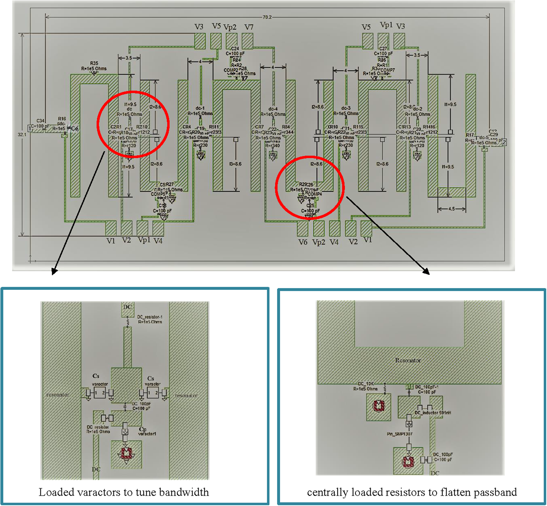
Fig. 1. Proposed six-pole microstrip filter with reconfigurable bandwidth and equivalent high-Q performance.
The tuning mechanism of the proposed filter
For our investigation, firstly a pair of resonators with the proposed tuning network is demonstrated and examined in Fig. 2, where the software Microwave Office (AWR) [25] is used for simulation. As we all know, for the conventional case, i.e. without shunted varactor Cp, if we tune the varactor Cs, only the lower resonance peak is shifted accordingly, as shown in Fig. 3(a). In order to tune the bandwidth while maintaining the center frequency unchanged, most of the reported work, like the design described in [Reference Chiou and Rebeiz4, Reference Chiou and Rebeiz5], usually adopted additional varactors to adjust the frequencies of resonators, leading to the increased complexity of DC bias circuits. However, for our proposed tuning network, it is interesting to see if we kept Cs = 3.4 pF, when tuning Cp from 5 to 23.9 pF, the upper frequency peak is successfully shifted. While if we kept Cp = 5 pF, when tuning Cs from 1 to 3.4 pF, both frequency peaks are shifted together, but the lower one is shifted more significantly than the upper one. These features can be easily understood by using even/odd mode theory [Reference Hong26, chapter 7] and not be repeated here. Apparently, the proposed tuning network offers a possibility to adjust bandwidth without a need to tune the electrical length of resonators anymore. Furthermore, varactors Cs and Cp could be treated to have an independent effect on bandwidth tuning. In other words, by tuning Cp, the upper side of the passband could be controlled; by tuning Cs, the lower side of the passband could be mostly controlled. For better demonstration, Fig. 4(a) describes an example of a three-pole filter model based on the proposed tuning network. A set of tunable responses are given in Figs 4(b) and 4(c). Inspecting the responses given in Fig. 4(b), it is clear to see that individually tuning varactor Cp/Cs results in the upper/lower bandedge shifted, while has little effect on the opposite one. In this way, Fig. 4(c) depicts the simulated S 21 of such a three-pole filter, with bandwidth varying from 300 to 70 MHz. Moreover, it should be highlighted that in comparison to the three-pole reconfigurable filter proposed in [Reference Chiou and Rebeiz4, with 4 DC voltage], the proposed one requires less DC bias (3 DC voltage) due to its simpler bandwidth tuning mechanism.

Fig. 2. The proposed configuration for controlling the internal coupling of the filter.

Fig. 3. S21 of (a) conventional case by only tuning Cs. (b) Proposed case by tuning Cp, with Cs kept fixed. (c) Proposed case by tuning Cs, with Cp kept fixed.

Fig. 4. (a) Ideal model of three-pole tunable filter based on the proposed tuning method. (b) Frequency responses by individually tuning varactors Cs and Cp. (c) The proposed three-pole filter with a wide bandwidth tuning ratio.
Lossy circuit technique
In order to achieve the desired insertion loss variation in the passband at each tuning state, this study adopts a lossy circuit technique by centrally loading resistors at the middle four resonators (see Fig. 1). Indeed, such a lossy technique was firstly presented in [Reference Hong, Ni and Iglesias21] and further discussed in [Reference Rao, Guo, Ni, Hong and Iglesias22] as research outcomes of the author's group. In general, centrally loading resistors at resonators produces more insertion losses at the middle of passband by power absorption, which compensates rounded-off passband edges and thus improves the insertion loss variation. In comparison to other lossy circuit techniques [Reference Guyette, Hunter and Pollard16, Reference Miraftab and Yu17], this one offers an almost unchanged in-band performance until-over flatten. Hence, there is no need to re-adjust the parameters of the reference filter, which means the synthesis processes of filter design and lossy circuit technique can be independently performed. Such characteristics are very promising and convenient to design a tunable lossy filter. As an illustration, Fig. 5 plots simulated responses of the proposed tunable filter at one tuning state, with and without the lossy circuit technique applied. Obviously, by centrally loading resistors of 50 Ohm at 3rd and 4th resonators, the insertion loss variation and return loss in the passband are enhanced, at the cost of an increased absolute insertion loss.

Fig. 5. The impact of centrally loaded resistors on improving passband flatness of the proposed tunable filter.
The associated challenge to design tunable loss filter is ideally the required loaded resistors at different tuning states should be different, since the rounded-off bandedge effect is varied against reconfigurable bandwidth. To this aim, the Pin attenuator SMP1307 from Skyworks is employed in the fabrication, whose obtainable series resistance could be continuously tuned from 10 to 80 Ohm by changing forward current from 100 to 1 mA (see in Fig. 6).

Fig. 6. Series resistance of SMP1307 versus current at 100 MHz [27].
Simulated and measured results
To validate the circuit concept proposed in the above section, a six-order tunable microstrip filter presented in Fig. 1 is demonstrated through both EM simulation and experimentally measured results, where the substrate RT/Duriod 6010 with a relative dielectric constant ɛr = 10.2 and thickness h = 1.27 mm is used. All the EM simulations are performed using a commercially available tool SONNET [28]. Detailed information about the components used for fabrication can be found in Table 2.
Table 2. The detailed information about components used for fabrication

Figure 7 depicts the simulated results of the proposed filter with five selected bandwidth tuning states, where the proposed design can obtain the desired channel bandwidth from 60 to 466 MHz in a continuous way, with center frequency almost unchanged. In general, by loading resistors, each state accomplishes a flat passband. The detailed frequency responses of each state can be found in Fig. 8.

Fig. 7. Simulated results for required bandwidth tuning states from 60 to 466 MHz.

Fig. 8. Simulated full S-parameters of (a) state 1. (b) State 2. (c) State3. (d) State 4. (e) State 5.
For the experimental demonstration, Fig. 9 illustrates the photo of the fabricated tunable filter with enhanced performance. Figure 10 clearly demonstrated a set of measured frequency responses of this fabricated sample, where the lossy circuit technique has been applied. The detailed information about DC bias setting for each state can be found in Table 3. Firstly, it is promising to see this fabricated sample addresses a wide 1 dB-bandwidth tuning range, covering from 49 to 478 MHz, with a tuning ratio around 10:1. Secondly, resulting from different resistors loaded at different tuning states, the filter generally obtains a flat passband within the tuning range. Moreover, it can be noted that the center frequency shift is visible at some states, which can be compensated by improving the resolution of DC supplier. Figure 11 displays the full S-parameters of three selected states, with bandwidth covering from wideband to narrowband. It should be highlighted that for the narrowband states of 49 and 59 MHz, the passband flatness is achieved by detuning resonators (predistortion technique) instead of centrally loading resistors, which is different from the simulated case because the fabricated dispassion losses are much higher than simulation. During the measurement, at the above narrowband states, the fabricated sample showed greater losses (due to tolerance of fabrication tolerance and SPICE models of varactors) than that of the simulated one, under the condition of no techniques to flatten the passband applied. Therefore, in the step to flatten the passband, the required values of centrally loaded resistors are out of range. Instead, it is found that at these narrowband states, the predistortion technique can help to achieve good passband flatness.

Fig. 9. Fabricated six-pole tunable filter with equivalent high-Q performance.

Fig. 10. The measurement results of the proposed six-pole tunable lossy filter.
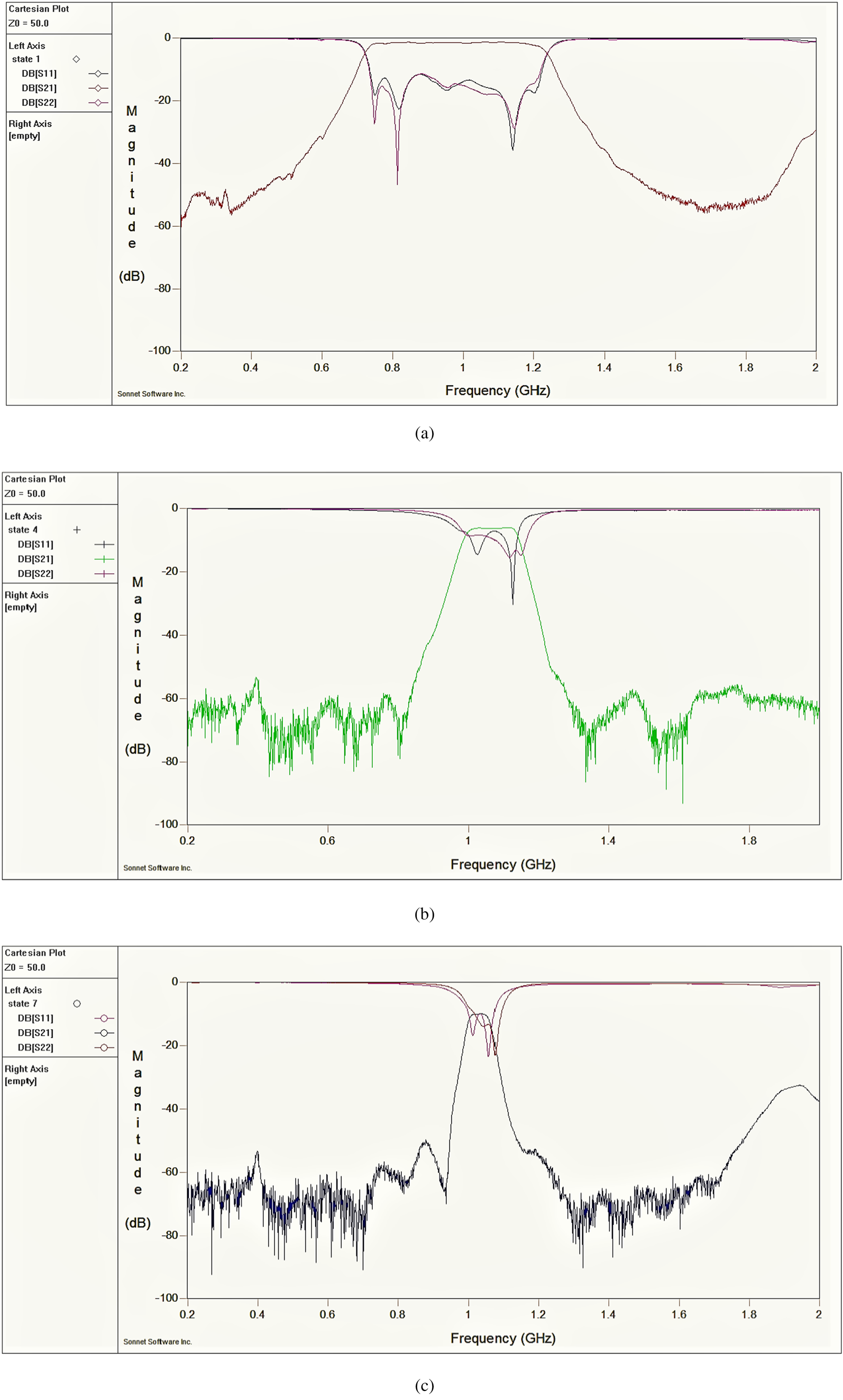
Fig. 11. Full S-parameters of (a) State 1_478 MHz. (b) State 4_125 MHz. (c) State 7_49 MHz.
Table 3. The detailed information about DC bias for each state

Conclusion
In this paper, a novel six-pole tunable IF lossy filter has been presented, analyzed, and experimentally verified, which addressed diverse advantages, including large bandwidth tuning ratio close to 10:1, low insertion loss variation at each tuning state, high selectivity, and simple DC control circuits. Table 4 summarized the detailed normalized performance of the proposed filter at three selected states, in comparison to the desired mask. In general, the proposed design almost successfully meets the required specifications, except for the normalized narrowband isolation achieved at the bandwidth of 49 MHz. To the authors' knowledge, this is the first time to present a tunable lossy filter with such attractive performance, which will find applications in demanding sub-systems including reconfigurable converters for satellite communications.
Table 4. Detailed comparisons among the measured and desired masks

 Jia Ni received the B.Eng. degree in electrical engineering from the Nanjing University of Science and Technology, Nanjing, China, in 2008, and the Ph.D. degree from Heriot-Watt University, Edinburgh, UK, in 2014. From 2014 to 2019, she has been a Post-Doctoral Research Fellow with the Microwave and Antenna Engineering Group, Heriot-Watt University, involved with research on reconfigurable microwave filters, microwave lossy filter, multilayer circuit design, and antenna (array) design. Since 2020, she works as a senior antenna system engineer in CelestiaUK Ltd.
 Jiasheng Hong received the D.Phil. degree in engineering science from the University of Oxford, UK, in 1994. He then joined the University of Birmingham, UK, until 2001 when he moved up to Edinburgh to join Heriot-Watt University, UK, and is currently a Professor leading a team for research into advanced RF/microwave device technologies. He has authored and co-authored over 200 journal and conference papers in this field and has published four relevant books – Microstrip Filters for RF/Microwave Applications (Wiley, 1st ed., 2001, 2nd ed., 2011), RF and Microwave Coupled-Line Circuits (Artech House, 2nd ed., 2007), Balanced Microwave Filters (Wiley, 2018), and Advances in Planar Filters Design (IET, 2019). He is a Fellow of IEEE, a member of the IEEE MTT Technical Committees, the Subject Editor (Microwave) for Electronics Letters, an Associate Editor of IET Microwaves, Antennas & Propagation and International Journal of RF and Microwave Computer Aided Engineering.
 Petronilo Martin Iglesias (M’12) was born in Caceres, Spain, on April 23, 1980. He received the Telecommunication Engineering degree from the Polytechnic University of Madrid, Madrid, Spain, in 2002, and the Master degree from the University of Leeds, Leeds, UK, in 2012. He has been working in the industry for over 10 years as a Microwave Engineer involved with active (high-power amplifiers for radar applications) and passive (filters, multiplexers, couplers, etc.) RF hardware design, including 2 years as a Radar System Engineer with Indra Sistemas, ISDEFE S.A., and Thales Alenia Space Spain. Since Summer 2012, he has been involved with research and development and project support activities related to RF passive hardware developments for the European Space Agency. His research interests are filter synthesis theory, electromagnetic (EM) design, and high-power prediction, as well as advanced manufacturing techniques for RF passive hardware. From January 2021, he is part of the Microwave Instruments Section at ESA-ESTEC.


 Open access