


Introduction
The access of interior regions of glaciers is of interest for many areas of research ranging from terrestrial glaciology to extraterrestrial applications, but it is technologically challenging. For terrestrial applications there are numerous approaches to solutions (Talalay, Reference Talalay2016, Reference Talalay2020). Besides mechanical drilling also melting with hot water is a very successful method. However, both methods usually require a complex and thus expensive infrastructure that is not suitable for use in space or remote locations and usually do not allow for a minimally invasive deployment of instrumentation. Therefore, thermal drills (Ulamec and others, Reference Ulamec, Biele, Funke and Engelhardt2007; Talalay, Reference Talalay2020) are an attractive and well-established technology that is robust and cost-effective, particularly for small-scale applications. To minimize the time in the field and the logistic effort, a high melting speed and a high efficiency are crucial for any kind of drilling operations. In this respect, the shape of the hot point or melting head plays an important role. There are theoretical approaches and comparison measurements to determine the optimal shape (Shreve, Reference Shreve1962; Fomin and Cheng, Reference Fomin and Cheng1991; Talalay and others, Reference Talalay2019). For an equal heat distribution, a parabolic shape is the optimum.
Within the EnEx-RANGE project (Heinen and others, Reference Heinen2016), a swarm of melting probes (APU – Autonomous Pinger Units) was developed. EnEx stands for Enceladus Explorer, which is an initiative from the DLR Space Administration for the technology development for a future space mission to Saturn's moon Enceladus. The EnEx-RANGE project (Robust Acoustic autonomous Navigation in Glacial icE) focused on the positioning within this swarm of melting probes. Thirteen melting probes have been built and tested for autonomous operation and exploration of a glacial area. Each melting probe has a diameter of 8 cm and a length of ~1 m. The positioning of the probes within the network is mostly based on acoustic signals which are exchanged between the probes over distances of several tens of meters. The network provides a reference for the positioning and navigation for robotic probes within the instrumented volume. The tests were conducted on several glaciers in the European Alps and in Antarctica. Each melting probe was equipped with acoustic instrumentation and a local intelligence for ice navigation. In this paper, we report on this efficient melting probe (EMP) as a general device for glacial research. As EMP we refer to these melting probes, without the need of the acoustic instrumentation.
The EMP features a novel melting head geometry that optimizes the mass to surface area (see Fig. 1). As discussed above (Fomin and Cheng, Reference Fomin and Cheng1991), a parabolic shape of the melting head is an optimal geometrical choice for fast melting speeds. However, particularly large radii of the melting probe result in large masses of the head. This increases weight and material costs, but also requires a more efficient heating. This can be addressed by a concave melting head as pursued, e.g. by a probe of the German Aerospace Center (DLR) (Engelhardt, Reference Engelhardt2007). In our approach, we stick to the proposed parabolic shape and follow the concave approach with a melting head implementing a folded parabolic geometry. For a probe radius R, the inner part within $R/\sqrt {2}$ of the parabola is inverted (see Fig. 2). In this way, the length of the head remains shorter than in conventional parabolic designs and the amount of material is reduced. In addition, the heat flow of inserted heating cartridges is optimized by keeping a short distance to all melting surfaces and heat accumulation zones are reduced.

Fig. 1. Cutaway drawing of the melting head of the cylindrical melting probe.
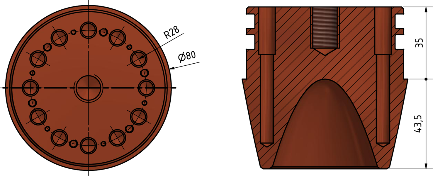
Fig. 2. Scheme of the melting head from the backside and in section view. All dimensions are given in millimeters (mm). Visible is the reversed parabolic shape in the center. The cylindrical body is put over the head from the top and the circular notches around the neck hold two O-rings for water-tightness. Heating cartridges are fed into the inner tubular recesses from the neck toward the front. The central thread was used for mounting the acoustic payload of the EnEx-RANGE system.
In this paper, we focus on the design of this novel melting head which has been registered as a patent (Linder and others, Reference Linder, Zierke, Heinen and Wiebusch2018, Reference Linder, Zierke, Heinen and Wiebusch2019). We present the melting speed performance of this EMP in its configuration within the EnEx-RANGE APU system. These results have been obtained in both laboratory and field measurements that were performed on two temperate Alpine glaciers and the Ross Ice Shelf in Antarctica.
Design and Configuration
In the EnEx-RANGE configuration, the EMP consists of a melting head, a cylindrical tube holding the control systems and a back plate (Heinen and others, Reference Heinen2016). The diameter is 80 mm and the length has been varied depending on the configuration between 0.6 and 1.2 m with the corresponding weight varying between 6 and 10 kg. The pressure housing in the current configuration is depth rated for 200 m (including a safety factor of 3). The back plate is equipped with a connector for the supply cable and an eye bolt for the retaining cable.
As supply cable, we use a standard three stranded copper wire, each with a cross-section of 2.5 mm2. In the tests on the temperate glaciers, 8 mm polypropylene ropes were applied to retain the probes. During expeditions on polar glaciers, a 3 mm steel retaining cable was attached with heat-shrink tubing to the supply cable, to avoid a freezing to melt channel walls. This cable package with a length of 50 m weighs ~10 kg. To prevent the freezing of the probe itself, the inner sides of the tube of the EMP were equipped with heater foils. No problems with respect to freezing of cables or the probe to the ice were encountered for any hole that was drilled during the campaign.
The EMP's pressure housing contains a data system with house-keeping sensors, a low-voltage power supply, a heater control system and a communication module. A commercial embedded computer system (MicroZedFootnote 1 or Raspberry PiFootnote 2 ) works as the data system (Eliseev and others, Reference Eliseev2019). As house-keeping sensors, the EMP uses several temperature sensors, a power sensor, a pressure sensor, an inertial measurement unit and a magnetometer. The heater control is based on TRIACs and controls several groups of heating elements. The communication module works via power line over the supply cable. At the surface, the EMP can be easily controlled with a notebook and a standard power line module. A photo of the whole setup as used in a field test (see below) is shown in Figure 3. Technical details of the system can be found in Weinstock (Reference Weinstock2019).

Fig. 3. Setup of the equipment as used on the Ross Ice Shelf in 2018.
The EMP head is shown in Figure 2. In the standard EnEx-RANGE configuration, the head contains 12 heating cartridges as heating elements. Each heating cartridge has a diameter of 6 mm, a length of 40 mm and nominal heating power of 200 W (typ. ±20 W). Depending on the availability of the voltage feed, cartridges rated for 120 or 230 V, but with the same heating power, were used. In total, this melting probe configuration has a power of 2.4 kW. The power of the probe can be varied by the heater control between zero and the total power in steps of 200 W. The positions of heating cartridges are optimized for good heat flow within the melting head by short distance to all melting surfaces. The positions are arranged on a circle with a radius of ~28.3 mm. This coincides with the turn of the parabola at the probe's radius divided by $\sqrt {2}$ . With this choice, the cross-sectional area projected on the horizontal has the same area within and outside the radius.
Performance in Field Tests and in the Laboratory
The performance of the EMP has been tested in the laboratory and in the field on several glaciers,that is, the Langenferner (Galos and others, Reference Galos2017) and the Mittelbergferner (Fischer and Kuhn, Reference Fischer and Kuhn2013), both glaciers in the European alps, and on the Ross Ice Shelf in Antarctica (Bentley and others, Reference Bentley, Glough, Jezek and Shabtaie1979). It was operated between depths of a few 10 cm (in the laboratory) and depths up to 40 m (limited by the length of the supply cable).
The EMP was tested on the Langenferner glacier in summer in 2017 and 2018. In 2017 seven EMP melting probes and in 2018 13 probes, all equipped with acoustics, were deployed in different swarm configurations. Four holes with a depth between 30 and 40 m and ~30 holes between 5 and 30 m were melted. The melting speed was determined to 3.2 m h−1 close to the surface for an electrical heating power of 1.8 kW. The surface ice at the test side was covered by thin layer of dust. Despite melting through this layer, we have not observed a reduction of the the melting speed. Convex head geometries were successfully tested by Kömle and others (Reference Kömle, Tiefenbacher and Kahr2018) and Li and others (Reference Li2020) to penetrate dust layers of the order of several millimeters to centimeters. Similar tests with this melting head have not been conducted yet.
On the Mittelbergferner, two EMP probes were deployed to depths of 18 m in the winter of 2019. The observed speed for these holes was up to 3.5 m h−1 for a power of 1.9 kW. The temperatures of both glaciers during these tests were close to, but slightly below 0°C as slow refreezing of melted holes was observed.
On the Ross Ice Shelf in 2018, an EMP was utilized for the deployment of radio antennas and emitters in the ice for the ARIANNA project (Barwick, Reference Barwick2007; Anker and others, Reference Anker2019). In total, one hole down to 40 m, three holes down to 20 m and several holes between 5 and 10 m were produced. The ice temperature was ~ −15°C near the surface and ~ −24°C in a depth of ~20 m. The typical speed in the near-surface firn was 7.5 m h−1. This speed reduced down to 4.1 m h−1 for the deepest hole at 40 m due to the higher density of the firn. We have normalized the measured speed in the firn ice to the nominal value of solid ice ρsolid ice = 916.8 kg m−3 assuming v firn × ρfirn = v solid ice × ρsolid ice. For the correction, we assume a depth-dependent ice density between ρfirn = 330 kg m−3 at the surface and ρfirn = 570 kg m−3 at a depth of 20 m, which had been measured in a previous season (Barwick, Reference Barwick2018). In contrast to the other measurements, we observed in the Ross Ice Shelf drilling operations the disappearance of the melt water in the holes due to draining into the firn. Due to the uncertainty in the temperature, the measured speed is an underestimate of the obtainable speed at 0°C.
A measurement of the speed of the EMP in the laboratory has been conducted by Wendland (Reference Wendland2018). For this measurement, ice volumes were created in a plastic barrel, which were situated in a freezer or in a refrigerated container. Ice temperatures were typically −18°C when starting a measurement but slowly increasing with time to 0°C. The EMP was set on top of the ice volumes and melted to ~30 cm depth. These measurements were repeated several times to verify the reproducibility and to measure the speed for different power settings. Also for this measurement, the temperature uncertainty results in an underestimate of the obtainable speed at 0°C.
The observed speed values are shown in Figure 4 as function of the electrical heating power. For reference, we compare the observed melting speed with an idealized maximum model, where the total input power P is spent for melting, i.e. without losses by convection and heat conduction. The enthalpy of fusion of water ice is H = 333.5 kJ kg−1 at 0°C under a wide range of pressures (Lide, Reference Lide1998). For ice colder than 0°C additionally, the heating of the ice by a temperature ΔT has to be taken into account, where the specific heat capacity is C P = 2.1 kJ kg−1 K−1. This results (Ulamec and others, Reference Ulamec, Biele, Funke and Engelhardt2007) in a maximum melting speed of

Using a cross-sectional area of A = 50.3 cm2, corresponding to the diameter of 8 cm of the EMP, and a density of water ice of ρ = 916.8 kg m−3, a maximum melting speed of 2.34 m h−1 kW−1 for ice at 0°C and, respectively, 2.08 m h−1 kW−1 for − 20°C is obtained. The observed speed values correspond to 78.4% of the optimum model for 0°C and to 86.6% for − 20°C, respectively. This represents a high melting efficiency of the EMP.

Fig. 4. Observed speed of the EMP in dependence of the electrical heating power. The ideal model curves and the measurements are marked in the legend with the abbreviations: Lf, Langenferner; Mf, Mittelbergferner; RIS, Ross Ice Shelf; Laboratory. At the Ross Ice Shelf, a correction with respect to the ice density has been applied.
For a more quantitatively comparable result, we define the specific power as the input power per unit area of the cross-section of the melting head. With this specific power, we normalize the speed as speed per specific power [(cm h−1) per (W cm−2) = cm3 W−1 h−1]. The distribution of the resulting speed values is shown in Figure 5. The mean of the obtained values is ~8.76 cm3 W−1 h−1. The spread of values has a standard deviation of 0.73 cm3 W−1 h−1. Measurements for different electrical power and ice temperatures, from the laboratory, and different glacial environments exhibit no systematic trend and are reasonably consistent. The different measurements are subject to various systematic uncertainties. In case of the Ross Ice Shelf measurement, the density correction for the firn ice introduces factors between 1.5 and 2.6 and is intrinsically uncertain. In case of wet holes as on the alpine glaciers and in the laboratory, the hole diameters were found to be larger than the actual probe. As this is equivalent to a larger effective cross-sectional area, the observed speed values per specific power tend to underestimate the actual value.

Fig. 5. Stacked histogram of the observed speed values per specific power as of Figure 4. The ideal model curves and the measurements are marked in the legend with the abbreviations: Lf, Langenferner; Mf, Mittelbergferner; RIS, Ross Ice Shelf.
A comparison of these measurements to other thermal drills with a similar power density is shown in Figure 6. A selection of several drills and measurements from Taylor (Reference Taylor and Splettstoesser1976), Classen (Reference Classen1977), Dachwald and others (Reference Dachwald2014), Kömle and others (Reference Kömle, Tiefenbacher and Kahr2018) and Talalay and others (Reference Talalay2019) is shown. In addition to the here discussed idealized model, the theoretical approach from Talalay (Reference Talalay2020), which accounts for a borehole enlargement during the drilling and an ice temperature of − 10°C, is included. The linear trend from Talalay (Reference Talalay2020) is also shown. It was determined by including 25 different references and a larger range of power density.
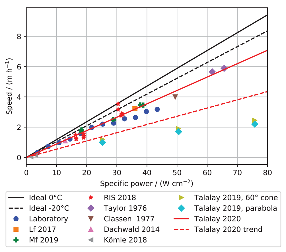
Fig. 6. Observed speed of the EMP and other drills in dependence of the specific power. The ideal model curves and the measurements are marked as before in the legend with the abbreviations: Lf, Langenferner; Mf, Mittelbergferner; RIS, Ross Ice Shelf. In addition to that other results are plotted and explained in the text.
Conclusions and Outlook
We have presented a melting probe that employs a new melting head design. This design combines the large surface contact area of a parabolic geometry with minimal mass and length. The performance has been tested in the laboratory as well as in Alpine and Antarctic glaciers. The tests have demonstrated that the melting probe can be operated with typical equipment of small-scale field camps including a small power generator and also be reliably retrieved. These tests showed a high melting speed which is found in cold ice at ~86.6% of the ideal upper bound that is neglecting possible heat losses. The typically achieved melting speed per specific power is 8.8 cm3 W−1 h−1. In comparison to other thermal drills of a similar power density, this is an excellent performance.
With these performance results combined with very moderate logistical requirements, the EMP system is applicable for the cost-efficient installation of instrumentation in glaciers at depths below a few meters. Based on the experience reported, we are following up on this design within the TRIPLE project line (Waldmann and others, Reference Waldmann2018) that is funded by the DLR Space Administration. Goal is the minimally invasive exploration of sub-glacial lakes in Antarctica, by delivering an autonomous underwater vehicle as payload of a melting probe. Within the TRIPLE-IceCraft project, we are currently developing a melting probe that can reach depths of several hundred meters. As a demonstrator, the penetration of the Ekström Ice Shelf is planned for winter 2021/2022.
Acknowledgments
This work has been accomplished within the framework of the Enceladus Explorer Initiative that is managed by the DLR Space Administration. The EnEx-RANGE project was funded by the German Federal Ministry of Economics and Energy (BMWi) by resolution of the German Federal Parliament under the funding code 50NA1501. We thank the ARIANNA project (US/NSF funded as NSF-1607719) for enabling and supporting the tests on the Ross Ice Shelf. We thank the EnEx-AsGAr project (BMWi funded as 50NA1708-50NA1709) for the support during the Mittelbergferner field test in 2019.


 Open access