

The basic principle of ECMO is to pass blood through an oxygenator to allow gas exchange. If the blood is driven by a pump, the pressure generated by the pump can be used to replace part or all the cardiac function.
When the blood is taken from a vein and returned via a vein, the system is known as veno-venous ECMO (Figure 3.1).
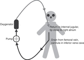
Figure 3.1 Veno-venous ECMO circuit, with drainage from a cannula inserted in the femoral vein (tip in the inferior vena cava) and the return cannula inserted in the internal jugular vein (tip in the superior vena cava, next to the right atrium).
A pump is required to move the blood through the circuit and across the membrane. The returned blood is mixed with the venous blood and then continues as normal (i.e. from vein to right heart to lungs to left heart to systemic circulation). If the proportion of blood going through the ECMO circuit is increased while the patient’s cardiac output remains the same, a greater proportion of ECMO blood will bring a higher concentration of oxygen (O2) to the right side of the heart. If the cardiac output increases while the ECMO blood flow remains the same, the proportion of oxygenated blood that arrives in the right side of the heart will be decreased. Analysis of blood gases in an arterial sample (obtained from the patient) will give the end result of the ECMO blood mixed with the patient’s blood, which has passed through the patient’s own lungs.
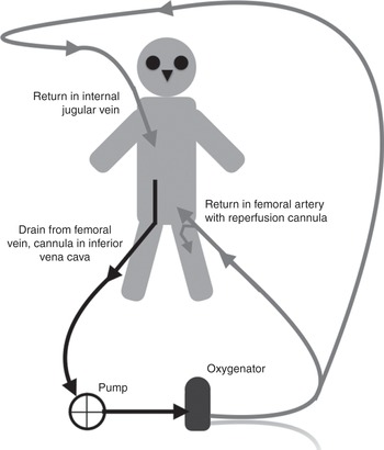
When the blood is taken from a vein and returned via an artery, the system is known as veno-arterial ECMO. The return cannula can be inserted in a peripheral artery (Figures 3.2 and 3.3) or the aorta (Figure 3.4). Alternatively, drainage can be from a cannula inserted in a peripheral vein with the return cannula inserted through the chest into the aorta (Figure 3.5).
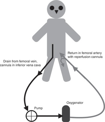
Figure 3.2 Veno-arterial ECMO circuit, with drainage from a cannula inserted in the femoral vein (tip in the inferior vena cava) and the return cannula inserted in the femoral artery.

Figure 3.3 Veno-arterial ECMO circuit, with drainage from a cannula inserted in the femoral vein (tip in the inferior vena cava) and the return cannula inserted in the subclavian artery.

Figure 3.4 Veno-arterial ECMO circuit, with drainage from a cannula inserted in the right atrium and the return cannula inserted into the aorta, through an open chest.
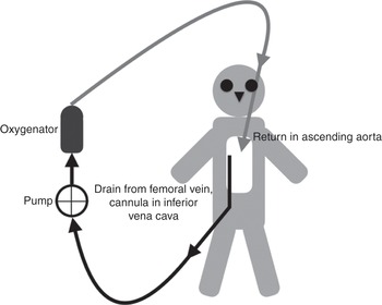
Figure 3.5 Veno-arterial ECMO circuit, with drainage from a cannula inserted in the femoral vein (tip in the inferior vena cava) and the return cannula inserted into the aorta, through an open chest.
In the absence of a pump, the blood would flow in the opposite direction, driven by the patient’s own blood pressure. If the pump generates a higher pressure than the patient’s own, the blood will go from vein to artery and bypass the function of the heart. This would introduce a shunt with the injection of venous blood (non-oxygenated) straight into the arterial system. An oxygenator is indispensable to add O2 into the returned blood. This system can then support a failed heart (by providing the pump support) or a failed lung (by providing the required gas exchange), or both a failed heart and lungs. Of note, the system can pump in line with the normal circulation (such as when a return cannula is inserted in the ascending aorta; Figure 3.4) or pump against the normal circulation (such as when a return cannula is inserted in the femoral artery; Figure 3.2).
Analysis of blood gases in an arterial sample (obtained from the patient) may lead to misinterpretation, as the sampled blood could be coming from the ECMO circuit only, the patient’s own circulation only, or both.
From these two basic approaches, a combination of drainage and access can be configured, including return in both an artery and vein. The chosen configuration will determine what support is provided, hence the mixed (and confusing) terminology of cardiac ECMO, respiratory ECMO, veno-venous ECMO, veno-arterial ECMO, veno-veno-arterial ECMO, etc. We prefer to refer only to the support being provided, rather than the type of ECMO, using cardiac ECMO when supporting the heart and lungs, and respiratory ECMO when supporting gas exchange.
Examples of the various configurations are shown in Figures 3.6, 3.7, 3.8 and 3.9.


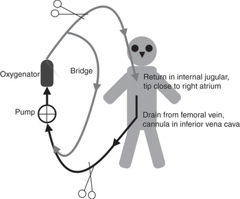
Figure 3.7 Veno-venous ECMO circuit, with drainage from a cannula inserted in the jugular vein and the return cannula inserted in the femoral vein (tip in the superior vena cava, next to the right atrium).

Figure 3.8 Veno-venous ECMO circuit, with drainage from two cannulas, each inserted in one of the femoral veins (one long cannula with the tip in the inferior vena cava and one short cannula with the tip in the iliac vein) and the return cannula inserted in the internal jugular vein (tip in the superior vena cava, next to the right atrium).
In the absence of a pump, a veno-arterial approach will become arterio-venous with the patient’s own blood pressure driving the blood through the oxygenator. This equates to introducing a new vascular bed through which part of the blood is diverted (blood will be pumped through the liver, kidneys, gut, skin and the ECMO circuit). Gas exchange will happen in the oxygenator.
In terms of circuitry, veno-venous and veno-arterial ECMO are identical and this will be discussed further in this chapter. Arterio-venous circuits are discussed in Chapter 13.
The principle components of the ECMO circuit include the cannula (discussed in Chapter 6), tubing, blood pump, oxygenator and heater/cooler (all discussed in this chapter). A diagram illustrating the circuit is shown in Figure 3.10.
Components of the ECMO circuit (except the cannula)
Tubing
The tubing comprises the pipes connecting the various elements of the ECMO circuit. Blood flows through them and they are joined to other components, such as the cannula and oxygenator. ECMO centres may have slightly differing configurations of tubing, but the basic principle is similar.
The tubing is transparent to allow clinicians to observe the blood colour and detect the accumulation of a thrombus. The tubing should be as short as possible but long enough not to impede the patient’s movement. Shorter tubing allows for less priming volume and decreases exposure of the blood to foreign surfaces and heat loss. Patient movements include passive mobilization (e.g. transport to the CT scanner) or active exercise (e.g. a patient on a fixed bike). Modifying the length of the circuit is possible but dangerous, as cutting the tubing can lead to air entrainment, blood loss, thrombosis or infection, as well as subsequent circuit rupture or disconnection.
The majority of tubing is made of polyvinyl chloride. The tubing is often heparin coated to improve biocompatibility, reducing the risk of thrombosis and a systemic inflammatory response as the blood is exposed to foreign material. The search for a more biocompatible material is ongoing, and different types of coating are being tested.
By convention, and to allow sufficient blood flow, adult tubing has an internal diameter of 3/8 inch.
The tubes can have side ports (Figure 3.11) to allow access for blood sampling or connection of other circuits, such as continuous renal replacement therapy. The side ports can also be used to give drugs or fluids.

Figure 3.11 Illustration of the side ports that can be added to an ECMO circuit.
Connections and divisions are areas of increased blood turbulence, increasing haemolysis and thrombus formation.
The high pressures on the arterial (return or after the pump) side of the ECMO circuit limit the use of access ports on this side. Rapid blood loss will occur if inadvertently opened.
The negative pressures generated on the venous side (drainage from the patient with negative pressure generated by the pump) means that air can be entrained into the circuit when accessing a port on this side. Air can cause pump malfunction or even return to the patient. Clear guidelines and careful handling of these ports are required. Protocols should be in place to manage inadvertent air entrainment, and qualified staff should be trained to deal with these situations (practising it repeatedly to be ready for the rare times it happens).
A bridge between the venous and the arterial lines (Figure 3.12) allows recirculation of blood within the ECMO circuit (note: many clinicians wrongly assume initially that the recirculation of blood is on the patient side).
The bridge could, in theory, be used during weaning of a patient from ECMO, maintaining high blood flow through the oxygenator. This is a dangerous manoeuvre, as the blood flow will be lower in some components of the circuit, such as the cannula, leading to the formation of a thrombus. A bridge can be used to recirculate blood while removing air, a technique that can prove life-saving when air has suddenly been entrained into the system. When not in use, the bridge is filled with priming fluid. Bridge tubing not in use should not be left full of stagnant blood.
Blood pump
Blood flow through the ECMO circuit is driven by a pump. Centrifugal pumps are now preferred to roller pumps as they cause less haemolysis and require less anticoagulation. This book assumes you will only use centrifugal pumps.
Centrifugal pumps operate by creating a fluid vortex formed by a rapidly spinning impeller. The impeller is magnetically levitated or spins on a small bearing (Figure 3.13). Magnetically levitated centrifugal pumps require no direct contact between the impeller and the pump housing, eliminating particle or heat generation. This reduces haemolysis and thrombus formation, and has a lower risk of mechanical failure.

Figure 3.13 Centrifugal pumps operate by creating a fluid vortex formed by a rapidly spinning impeller. The impeller is magnetically levitated or spins on a small bearing.
The impeller energy can dissipate in heat if no flow is created, but will usually be transformed into kinetic energy. This creates a negative pressure before the pump, entraining blood from the patient. The blood is then moved forward and positive pressure is generated in the returning limb of the circuit.
Centrifugal pumps are preload dependent and afterload sensitive. This means that the number of revolutions per minute of the impeller will not be the sole determinant of the flow through the circuit. If the circuit is occluded, the pump will continue to spin. If the occlusion is after the pump, the impeller will continue to spin but the pressure will increase.
The pump preload will decrease if the patient is hypovolaemic or if there is any obstruction to blood flow entering the pump (e.g. reduced venous filling due to a tension pneumothorax or kinking of the cannula/tubing). As the interruption is before the pump, the spin will continue but the energy from the impeller will dissipate in heat rather than flow, as no fluid will be sucked in.
The pump afterload will increase if the resistance to flow after the pump increases. This could be between the pump and the patient, such as observed in the case of a thrombus or kinks in the return cannula/tubing, or thrombus build-up in the oxygenator. In veno-arterial ECMO, when the cannula ends are not in the same vascular compartment, an increase in the patient’s own blood pressure will increase the afterload, and this in turn will decrease blood flow, even if the impeller is still revolving at the same rate.
Cannula choice (see Chapter 6) will therefore affect the pump flow as the length and diameter of the cannula will create a resistance to flow. In all circuits, the drainage cannula should always be wider than the return cannula to optimize potential flow.
Blood flow through a circuit driven by a centrifugal pump must be continually monitored with an ultrasonic flow meter. The pump speed will be constant, but the blood flow will be dependent on resistance before and after the pump.
Circuits with centrifugal pumps are completely non-occlusive; this means that there is a continuity from one end to the other, without one-way valves. If the pump stops, the blood can stagnate (such as in a veno-venous configuration) or flow in the reverse direction (such as in a veno-arterial configuration as the arterial blood pressure will be higher than the venous pressure, driving the blood from artery to vein). This can have catastrophic consequences in veno-arterial ECMO. The energy generated by the pump in a veno-arterial ECMO circuit must create a higher pressure than the patient’s own mean arterial pressure.
Oxygenator
Gas exchange occurs within the oxygenator (Figure 3.14). It is often referred to as an artificial lung, but all astute physicians will know that the lungs do much more than exchange gases. The oxygenator is only a gas-exchange interface.

Early oxygenators used to mix blood and gas bubbles, but membrane oxygenators have proven to be safer and more efficient (the blood and gas are separated by a membrane, allowing only the passage of gas).
Current oxygenators are based on the positioning of multiple hollow fibres creating channels, with the most commonly used material being polymethylpentene fibres. These fibres have better durability and cause less haemolysis. The incidence of plasma leakage is also reduced.
As blood is pumped through the oxygenator casing, the gas (known as sweep gas) flows through the inside of the hollow fibres. The fibre walls (of polymethylpentene) are then the interface through which O2 and CO2 transfer occurs.
Oxygenators are made of a case through which the blood is passing and fibres immersed in it, with gas flowing through the fibres. The case will be immersed in a heating/cooling bath to allow thermoregulation.
Gas is delivered to the oxygenator via a blender with a flowmeter that is titrated to regulate gas flow.
In the oxygenator, O2 transfer is dependent on: (1) the surface area of the membrane; (2) the fraction of delivered O2 in the sweep gas; and (3) the time the blood is in contact with the membrane. The surface area has been substantially increased by using hollow fibres and should not be a limiting factor in current adult oxygenators. In fact, increasing blood flow increases the number of fibres used and maximizes contact (so higher blood flow usually means a higher O2 concentration in the blood). This impact of increased surface area is greater than the decrease in transfer related to the blood flowing faster in the oxygenator (faster transit time decreases the available time to transfer). If all the fibres were to be used, decreasing the blood flow would probably increase oxygenation, allowing full blood saturation, but this situation is never seen clinically (if one can ever say ‘never’ in a clinical situation…). If all the fibres are used, or too many are out of action due to the presence of microthrombi, a second oxygenator will increase the surface area and improve O2 delivery (Figure 3.15). The efficacy of adding an oxygenator (in parallel) is disputed, as modern oxygenators are built in such a way as to maximize use of the possible flow attainable with a 3/8 inch tubing. In practice, a second oxygenator is used when everything else has failed. The key benefit is that it gives reassurance that one oxygenator can act as a back-up if the other one was to fail. The risk is the increased number of connectors in the circuit (weak points) and ensuring that high enough blood flow is maintained in all parts of the circuit to prevent thrombosis.

Figure 3.15 A second oxygenator inserted in the ECMO circuit to increase overall membrane surface area. It is important for the blood flow to be maintained at a high enough rate to avoid a thrombus building up in the fibres.
CO2 is quickly transferred from the blood to the gas, as long as the concentration of CO2 is lower in the gas than in the blood. This means that CO2 elimination will primarily be determined by the sweep gas flow. If the gas flow is high, the gas will always have less CO2 than the blood and a gradient of diffusion will be maintained. The entire dissolved CO2 can be eliminated in an ECMO circuit and can easily match the physiological CO2 production.
Condensation of water within the oxygenator will decrease efficiency and the oxygenator needs to be regularly flushed with a high gas flow to remove the accumulated moisture.
Heat exchangers
Heat exchangers are essential to keep the patient warm. Various systems are available, but most are based on circulating warm water around the oxygenator or tubing.
The water used in these circuits can be contaminated by various organisms. While the water is usually not in contact with the blood, these organisms can be released into the atmosphere and may be a danger to the patient(s), staff and relatives. Local decontamination procedures should not be ignored.
A recognized complication is the failure of the heat exchanger (occurring in around 2% of patients). This is not always recognized immediately, as it is often wrongly attributed to the overall condition of the patient.
Heat exchangers allow the control of temperature within a tight, predefined range, such as is required after cardiac arrest.
Heat exchangers also allow cooling of the patient to decrease overall metabolism, leading to less CO2 production and less O2 consumption.
Circuit monitoring
The primary goal in monitoring the circuit is to prevent patient complications. The various elements that require monitoring are listed in Table 3.1.
| Measurement/assessment | Rationale |
|---|---|
| Blood flow rate (L/min) through ECMO circuit, measured using ultrasonic flowmeter | Main determinant of arterial oxygenation; loss of flow requires urgent intervention |
| Pump motor speed (revolutions/min) | Adjusted to provide optimum flow; indicator of motor failure |
| Sweep gas flow rate (L/min) and O2 concentration | Important factors determining CO2 removal and oxygenation |
| Transmembrane gradient (difference between pre- and post-oxygenator circuit pressure) (mmHg) | Increasing transmembrane pressure gradient may indicate failing oxygenator |
| Post-oxygenator O2 saturation if patient not achieving target partial pressure of O2 in arterial blood (PaO2) | Less than fully saturated blood on 100% O2 may indicate failing oxygenator |
| Plasma-free haemoglobin (if available) | To assess degree of intravascular haemolysis |
| Bedside point-of-care anticoagulation testing (e.g. activated clotting time, thromboelastography) | To allow titration of heparin dosing and guide administration of blood products |
| Temperature of water bath (warming of blood passing through oxygenator) | To allow adjustment of blood temperature to desired levels |
| Inspection of circuit, oxygenator and cannula site | Presence of thrombus, fibrinous deposits, air, mechanical problems, infection and decannulation |
Monitoring of the circuit is coupled with monitoring of the patient. Monitoring allows troubleshooting of issues, prevention of problems and an understanding of how the patient is progressing. Various pressures and flows can be measured in the circuit but the ‘human touch’ is important (or visual inspection, to be more precise). Monitoring of other parameters and the patient is discussed in Chapter 4.
Pressure monitoring
Pressure can be measured in three locations in an ECMO circuit as shown in Figure 3.16.
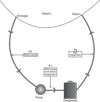
Figure 3.16 Pressure can be monitored in various locations in the ECMO circuit: after the pump and before the oxygenator (P1), after the oxygenator (P2) and before the pump (P3).
Pre-oxygenator pressure is measured after the pump and before the oxygenator. This pressure will increase as a result of resistance downstream, such as if thrombi have built up in the oxygenator or the return tubing is occluded.
Post-oxygenator pressure is measured after the oxygenator and will increase if any obstruction occurs in the tubing and/or cannula returning the blood to the patient.
Pre-centrifugal pump pressure is measured in the tubing before the pump. This pressure will be negative, as the pump is creating a negative pressure that entrains blood from the patient to the pump. A more negative pressure indicates that more force is required to drain the blood. Ideally this pressure will read around –60 mmHg. A value that is more negative than –100 mmHg will increase blood trauma and the release of free haemoglobin. There is a risk of entraining air in the circuit through the measuring port, and some centres have decided not to measure this pressure. It is, however, an invaluable clinical indicator of patient intravascular volume status, and of potential blood trauma. Collapse of the veins on the drainage cannula because of excessive suction should not happen when using this measurement. ‘Chattering’ or ‘fluttering’ of the drainage line should not be seen. Some systems (e.g. CardioHelp/HLS; Maquet) have an integral negative-pressure monitoring in an all-in-one circuit (see ECMO circuit selection, this chapter).
The calculated difference between pre- and post-oxygenator pressure is called the transmembrane pressure. An increase in transmembrane pressure indicates an occlusion in the oxygenator, usually due to thrombus formation. The trend should be observed on a regular basis, in conjunction with post-oxygenator blood gas measurements, to detect potential oxygenator failure.
Blood gas monitoring
Blood gases can be obtained intermittently or measured continuously from the circuit and are used to monitor the function of the oxygenator. A deteriorating partial pressure of O2 in arterial blood (PaO2) after the oxygenator indicates failure and is sometimes coupled to an increase in transmembrane pressure (Figure 3.17). The PaO2 measured before the oxygenator indicates how desaturated the venous blood is. Measuring the partial pressure of CO2 in the arterial blood (PaCO2) before and after the oxygenator gives a good indication of the ventilatory property of the oxygenator.

Sampling is done carefully to avoid excessive loss of blood, as the pressure at the sampling point can be very high. To ensure reliable and comparable results, blood gases obtained from the circuit are measured with the sweep gas set at 100% oxygen.
Changing an oxygenator is a relatively straightforward procedure involving cutting the connecting tubing. It is always carried out in aseptic conditions by perfusionists or ECMO specialists. Predicting oxygenator failure is vital to ensure that the change of oxygenator is a planned procedure rather than having to be carried out as an emergency.
In addition to blood gases, other components of the blood that influence circuit management can be analysed. This includes an assessment of the anticoagulation (see Chapter 7) or products of blood degradation. The level of free haemoglobin is a good indicator of stress on the circuit and will decrease with lower blood flow. A higher level of free haemoglobin will often be seen when the suction pressure is more negative.
Flow rate
Total blood flow through the circuit is continuously monitored with an ultrasonic flow meter placed on the return tubing between the pump and the patient.
When the circuit is configured to include more than one return or access cannula, the flow in each arm should be measured and recorded (Figure 3.18).

Figure 3.18 ECMO circuit with two drainage cannulas and one return cannula. Flow probes are positioned so that the flow in each arm can be measured.
The flow rate through any tubing should not fall below 1.5 L/min (we advocate at least 2 L/min and usually run the flow at no less than 2.5 L/min). A low blood flow will lead to blood stagnation and thrombus development.
In cases of configuration with multiple cannulas, it may be appropriate to simplify the circuit as soon as the flow can be decreased. (It is better to remove a cannula than to keep flow rates high leading to blood trauma. A venous cannula can be removed easily, even when the ECMO is running; see Chapter 6.)
Low-flow alarms may be caused by a low pump preload (not enough blood being sucked in, e.g. caused by massive bleeding leading to the vein collapsing on the drainage cannula, or an intense inflammatory response leading to intense vascular extravasation), a high pump afterload (patient hypertension, a kink in the return lines, a thrombus in the oxygenator) or pump failure, including air being trapped in the pump head. A low flow rate can simply be due to a pump being incorrectly set and revolving at a too low rate. Another reason is the alarm limits being set incorrectly in relation to the required blood flow.
‘Human touch’ or clinical inspection
Regular and methodical visual checks of the integrity of the circuit and all components should not be underestimated.
The blood colour in the drainage and return cannula should differ when the oxygenator is in use.
The gas tubing should be connected and the gas flowmeter should indicate the correct flow rate.
The temperature of the heat exchanger should remain as set.
Thrombus formation in the circuitry will be noticed first by a nurse conducting hourly routine checks of the tubing and oxygenator with a pen torch.
Kinks or damage to the circuit can be prevented by regular visual checks.
The integrity of all connections and ensuring sutures and tapes are in place can be life-saving. Dislodgement of a cannula can be prevented by regular careful inspection of all sutures (Figure 3.19).

Figure 3.19 Sudden dislodgement of a venous cannula that led to thrombosis.
The distinctive sound of air in a centrifugal pump may trigger emergency intervention before any alarms are set off.
ECMO circuit selection
ECMO use has increased due to the developments made in circuit design. Fully integrated systems are now available, rendering training and monitoring easier. Smaller, more compact systems facilitate patient transport and mobilization (Figure 3.20).

Figure 3.20 Fully integrated circuits are now available.
All circuits provide the same function, and choice will be guided by cost and training requirements. Fully integrated systems are ideal for units with low usage or high staff turnover. Bespoke systems (Figure 3.21) are suited for units with complex patients or when undertaking complex types of support requiring greater versatility. These bespoke units allow the incorporation of a second oxygenator and the addition of other devices to the ECMO circuit. Some of the pumps on offer can be used as ventricular assist devices. Most of them have excellent safety and longevity records.

Figure 3.21 A bespoke ECMO circuit.
ECMO circuit maintenance
A rigorous programme of maintenance needs to be in place to ensure the pumps and other components are in perfect working order, and sufficient stocks of tubing, connectors and oxygenators are required.
An ECMO circuit can be primed with crystalloid fluids in advance of its use, as long as a strict aseptic technique is used. This circuit can be kept in a safe area for several weeks. The benefit of a primed circuit that is immediately available is obvious in case of sudden mechanical failure.
Failure is often not an option (back-up equipment must be available, as mechanical failure may happen even in perfectly maintained devices). Bespoke systems allow greater flexibility, as only the broken component (usually the pump motor) needs replacing.
Key points
ECMO circuits should be as simple as possible.
Modern centrifugal pumps are used in most systems. These are preload dependent and afterload sensitive.
Monitoring of circuit pressures and blood flow is vital.
Visual inspection is paramount to ensure circuit integrity.


