


1 Introduction
The wake flow of a wind turbine features a velocity deficit owing to the energy extraction. As a result, a downstream turbine experiences lower wind speeds and generates less power. The far-wake flow of a turbine has been extensively reported to present low-frequency oscillations, usually referred to as wake meandering. The Strouhal number of the meandering is reported to be 0.15–0.25 (Medici & Alfredsson Reference Medici and Alfredsson2008), and its peak is estimated to be 0.28 (Chamorro et al. Reference Chamorro, Hill, Morton, Ellis, Arndt and Sotiropoulos2013) or 0.23 (Okulov et al. Reference Okulov, Naumov, Mikkelsen, Kabardin and Sørensen2014), both at five diameters downstream of the turbine. The wake meandering induces large-scale unsteadiness and modifies the interaction of aligned turbines. Furthermore, the strong turbulence production within the oscillating wake flow enhances the fatigue loading on downstream turbines (Larsen et al. Reference Larsen, Madsen, Thomsen and Larsen2008). Therefore it is of critical importance to predict the development of the turbine far-wake flow and the associated meandering motion (España et al. Reference España, Aubrun, Loyer and Devinant2012; Larsen et al. Reference Larsen, Madsen, Larsen and Hansen2013).
Low-frequency oscillation of turbine wake flow can be induced by intrinsic wake instabilities, originating from, e.g. the instability of helical vortices shed from the tip of each turbine blade. These vortices interact with the vorticity field due to the root vortices and the rotor hub, and are subject to long-wave, short-wave and mutual inductance instabilities before breaking down to coherent and turbulent structures that can travel up to 30–40 rotor diameters downstream of the turbine (Widnall Reference Widnall1972; Okulov & Sørensen Reference Okulov and Sørensen2007; Ivanell et al. Reference Ivanell, Mikkelsen, Sørensen and Henningson2010; Sørensen, Naumov & Okulov Reference Sørensen, Naumov and Okulov2011; Sherry et al. Reference Sherry, Nemes, Jacono, Blackburn and Sheridan2013; Hattori & Fukumoto Reference Hattori and Fukumoto2014; Sarmast et al. Reference Sarmast, Dadfar, Mikkelsen, Schlatter, Ivanell, Sørensen and Henningson2014; Quaranta, Bolnot & Leweke Reference Quaranta, Bolnot and Leweke2015). Vortex meandering resulting from mutual induction of helical vortices followed by downstream large-scale coherent structures has been reported (Bhaganagar & Debnath Reference Bhaganagar and Debnath2014). However, as revealed in experiments, the signature of tip vortices is only significant up to 1–2 rotor diameters downstream of the turbine, and the frequency of the far-wake meandering motion is independent on the operating conditions of the turbine (Chamorro & Porté-Agel Reference Chamorro and Porté-Agel2010; Okulov et al. Reference Okulov, Naumov, Mikkelsen, Kabardin and Sørensen2014). It is therefore doubtful if these relatively small-scale near-wake tip vortices may induce large-scale far-wake oscillations. For the far-wake flow, Schröttle, D”ornbrack & Schumann (Reference Schröttle, D”ornbrack and Schumann2015) simplified it as the combination of an atmospheric shear and a Lamb–Oseen vortex, and observed an instability induced flow oscillation. Since the frequency of far-wake meandering typically is lower than that of the turbine rotation, Iungo et al. (Reference Iungo, Viola, Camarri, Porté-Agel and Gallaire2013), Viola et al. (Reference Viola, Iungo, Camarri, Porté-Agel and Gallaire2014) have studied the instability of turbine hub vortices, which also oscillate at low frequencies. However the modes associated with these instabilities are concentrated around the wake centre.
Another hypothetical mechanism for far-wake meandering is the development of large-scale free-stream eddies. This hypothesis is based on the observation that the meandering is intermittent and dominated by a stochastic pattern (Larsen et al. Reference Larsen, Madsen, Bingöl, Mann, Ott, Sørensen, Okulov, Troldborg, Nielsen, Thomsen, Larsen and Mikkelsen2007), nevertheless a periodic signature of the meandering related to vortex shedding has been observed in wind tunnel studies (Medici & Alfredsson Reference Medici and Alfredsson2006). It is assumed that small-scale eddies (i.e. smaller than the rotor diameter), which constitute the high-frequency part of the turbulence spectrum, are responsible for diffusive effects in the wake only, whereas the low-frequency part, composed of eddies larger than the rotor diameter, contributes mainly to transport the wake as a whole (España et al. Reference España, Aubrun, Loyer and Devinant2012). Larsen et al. (Reference Larsen, Madsen, Bingöl, Mann, Ott, Sørensen, Okulov, Troldborg, Nielsen, Thomsen, Larsen and Mikkelsen2007, Reference Larsen, Madsen, Thomsen and Larsen2008) have established a physically based theory and subsequently a dynamic wake meandering model to predict the wake meandering induced by large turbulent eddies. The large-scale perturbations have also been found to induce meandering of a vortex flow via non-modal perturbation growth (Mao & Sherwin Reference Mao and Sherwin2012). In the present work, the most energetic inflow perturbation is calculated to examine effects of large-scale atmospheric eddies on far-wake oscillations, in order to verify this potential mechanism of meandering.
Most of the perturbation studies, e.g. linear stability and non-normality, have been related to the initial form of perturbations, computed by solving the linearized Navier–Stokes (NS) equations and their adjoint (Schmid & Henningson Reference Schmid and Henningson2001). There are a limited number of nonlinear exceptions, mainly related to nonlinear optimal initial conditions in pipe or boundary layer flow (Cherubini et al. Reference Cherubini, Palma, Robinet and Bottaro2010; Pringle & Kerswell Reference Pringle and Kerswell2010; Monokrousos et al. Reference Monokrousos, Bottaro, Brandt, Vita and Henningson2011; Rabin, Caulfield & Kerswell Reference Rabin, Caulfield and Kerswell2012; Kerswell, Pringle & Willis Reference Kerswell, Pringle and Willis2014). For boundary perturbations, the linear most energetic solution has been calculated in vortex flow and channel flow (Mao, Blackburn & Sherwin Reference Mao, Blackburn and Sherwin2013), and a two-dimensional (2-D) nonlinear optimal solution to suppress vortex shedding in the cylinder wake flow has been reported (Mao, Blackburn & Sherwin Reference Mao, Blackburn and Sherwin2015).
In this work, a three-dimensional (3-D) nonlinear solver to calculate the optimal inflow perturbation is developed based on a well established linear counterpart (Mao et al.
Reference Mao, Blackburn and Sherwin2013). The numerical challenge of such a nonlinear calculation is that the developing history of the flow, which easily exceeds
 $10^{4}$
gigabytes, has to be saved for the integration of the adjoint equation. The benefit of this nonlinear calculation is that the dynamics of large-magnitude free-stream perturbations can be studied and nonlinear phenomena during perturbation developments, e.g. vortex shedding, transition to turbulence, can be taken into account, which is not possible using linear perturbation analyses. Besides revealing the mechanisms of wake meandering, the upper limit of the magnitude of meandering induced by free-stream eddies can be estimated in this nonlinear optimization study.
$10^{4}$
gigabytes, has to be saved for the integration of the adjoint equation. The benefit of this nonlinear calculation is that the dynamics of large-magnitude free-stream perturbations can be studied and nonlinear phenomena during perturbation developments, e.g. vortex shedding, transition to turbulence, can be taken into account, which is not possible using linear perturbation analyses. Besides revealing the mechanisms of wake meandering, the upper limit of the magnitude of meandering induced by free-stream eddies can be estimated in this nonlinear optimization study.
2 Algorithm
2.1 Governing equations
A cylindrical coordinate system, with
 $x$
,
$x$
,
 $r$
and
$r$
and
 $\unicode[STIX]{x1D703}$
representing the streamwise, radial and azimuthal coordinates, respectively, is adopted to study the flow around a wind turbine. The governing equations are the non-dimensional incompressible NS equations with a volume force term representing the wind turbine:
$\unicode[STIX]{x1D703}$
representing the streamwise, radial and azimuthal coordinates, respectively, is adopted to study the flow around a wind turbine. The governing equations are the non-dimensional incompressible NS equations with a volume force term representing the wind turbine:
 $$\begin{eqnarray}\unicode[STIX]{x2202}_{t}\boldsymbol{u}+\boldsymbol{u}\boldsymbol{\cdot }\unicode[STIX]{x1D735}\boldsymbol{u}+\unicode[STIX]{x1D735}p-Re^{-1}\unicode[STIX]{x1D6FB}^{2}\boldsymbol{u}=\boldsymbol{f}\quad \text{with}~\unicode[STIX]{x1D735}\boldsymbol{\cdot }\boldsymbol{u}=0,\end{eqnarray}$$
where
 $\boldsymbol{u}$
,
$\boldsymbol{u}$
,
 $p$
and
$p$
and
 $\boldsymbol{f}$
are velocity, pressure and volume force, respectively.
$\boldsymbol{f}$
are velocity, pressure and volume force, respectively.
 $Re$
is the Reynolds number based on the free-stream velocity and the radius of the turbine rotating disc.
$Re$
is the Reynolds number based on the free-stream velocity and the radius of the turbine rotating disc.
The variables in (2.1) can be decomposed as the sum of a steady base term and a perturbation term,
 $$\begin{eqnarray}(\boldsymbol{u},p,\boldsymbol{f})=(\boldsymbol{U},P,\boldsymbol{F})+(\boldsymbol{u}^{\prime },p^{\prime },\boldsymbol{f}^{\prime }).\end{eqnarray}$$
The base terms can be obtained by implementing a uniform free-stream inflow condition and integrating (2.1) until reaching a steady solution. Substituting (2.2) into (2.1) and removing the base components, the governing equations for perturbations are obtained,
 $$\begin{eqnarray}\unicode[STIX]{x2202}_{t}\boldsymbol{u}^{\prime }+\boldsymbol{U}\boldsymbol{\cdot }\unicode[STIX]{x1D735}\boldsymbol{u}^{\prime }+\boldsymbol{u}^{\prime }\boldsymbol{\cdot }\unicode[STIX]{x1D735}\boldsymbol{U}+\boldsymbol{u}^{\prime }\boldsymbol{\cdot }\unicode[STIX]{x1D735}\boldsymbol{u}^{\prime }+\unicode[STIX]{x1D735}p^{\prime }-Re^{-1}\unicode[STIX]{x1D6FB}^{2}\boldsymbol{u}^{\prime }=\boldsymbol{f}^{\prime }\quad \text{with}~\unicode[STIX]{x1D735}\boldsymbol{\cdot }\boldsymbol{u}^{\prime }=0.\end{eqnarray}$$
For clarity, these equations are denoted more compactly as
 $$\begin{eqnarray}\unicode[STIX]{x2202}_{t}\boldsymbol{u}^{\prime }-L(\boldsymbol{U})\boldsymbol{u}^{\prime }-\boldsymbol{u}^{\prime }\boldsymbol{\cdot }\unicode[STIX]{x1D735}\boldsymbol{u}^{\prime }-\boldsymbol{f}^{\prime }=0,\end{eqnarray}$$
where
 $L(\boldsymbol{U})$
is a linearized operator, which depends on the base flow and acts on the perturbations. This operator has been well investigated in stability analyses to calculate the linear unstable eigenmodes or optimal perturbations. The inflow perturbation and initial perturbation can be modelled as the inflow boundary condition and initial condition of (2.4), respectively. Since the present work focuses on the inflow perturbations, the initial condition of
$L(\boldsymbol{U})$
is a linearized operator, which depends on the base flow and acts on the perturbations. This operator has been well investigated in stability analyses to calculate the linear unstable eigenmodes or optimal perturbations. The inflow perturbation and initial perturbation can be modelled as the inflow boundary condition and initial condition of (2.4), respectively. Since the present work focuses on the inflow perturbations, the initial condition of
 $\boldsymbol{u}^{\prime }$
in (2.4) is set to zero so as to isolate effects of the inflow perturbations.
$\boldsymbol{u}^{\prime }$
in (2.4) is set to zero so as to isolate effects of the inflow perturbations.
The computational domain around the turbine disc, in which the governing equations are solved, is denoted as
 $\unicode[STIX]{x1D6FA}$
, the boundary of the domain is represented as
$\unicode[STIX]{x1D6FA}$
, the boundary of the domain is represented as
 $\unicode[STIX]{x2202}\unicode[STIX]{x1D6FA}$
and the inflow boundary is denoted as
$\unicode[STIX]{x2202}\unicode[STIX]{x1D6FA}$
and the inflow boundary is denoted as
 $\boldsymbol{B}$
. To simplify notation in the following derivations, introduce scalar products
$\boldsymbol{B}$
. To simplify notation in the following derivations, introduce scalar products
 $$\begin{eqnarray}\displaystyle \left.\begin{array}{@{}c@{}}\displaystyle (\boldsymbol{a},\boldsymbol{b})=\int _{\unicode[STIX]{x1D6FA}}\boldsymbol{a}\boldsymbol{\cdot }\boldsymbol{b}\,\text{d}\unicode[STIX]{x1D6FA},\quad \langle \boldsymbol{a},\boldsymbol{b}\rangle =T^{-1}\int _{0}^{T}\int _{\unicode[STIX]{x1D6FA}}\boldsymbol{a}\boldsymbol{\cdot }\boldsymbol{b}\,\text{d}\unicode[STIX]{x1D6FA}\,\text{d}t,\\ \displaystyle [\boldsymbol{a},\boldsymbol{b}]=\int _{\boldsymbol{B}}\boldsymbol{a}\boldsymbol{\cdot }\boldsymbol{b}\,\text{d}\boldsymbol{B},\quad \{\boldsymbol{a},\boldsymbol{b}\}=T^{-1}\int _{0}^{T}\int _{\unicode[STIX]{x2202}\unicode[STIX]{x1D6FA}}\boldsymbol{a}\boldsymbol{\cdot }\boldsymbol{b}\,\text{d}\unicode[STIX]{x2202}\,\unicode[STIX]{x1D6FA}\,\text{d}t,\end{array}\right\} & & \displaystyle\end{eqnarray}$$
where
 $T$
is a final time and
$T$
is a final time and
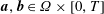 $\boldsymbol{a},\boldsymbol{b}\in \unicode[STIX]{x1D6FA}\times [0,T]$
.
$\boldsymbol{a},\boldsymbol{b}\in \unicode[STIX]{x1D6FA}\times [0,T]$
.
2.2 Actuator-disc model
An actuator-disc model with radius
 $R$
and streamwise thickness
$R$
and streamwise thickness
 $\unicode[STIX]{x0394}x$
is adopted to represent the wind turbine. Note that since the disc radius is used to define the Reynolds number, it has a unit value after non-dimensionalization. The aerodynamic force acting on the flow by the disc is
$\unicode[STIX]{x0394}x$
is adopted to represent the wind turbine. Note that since the disc radius is used to define the Reynolds number, it has a unit value after non-dimensionalization. The aerodynamic force acting on the flow by the disc is
 $$\begin{eqnarray}F_{aero}=-{\textstyle \frac{1}{2}}\unicode[STIX]{x03C0}C_{T}u_{d}^{2}R^{2},\end{eqnarray}$$
where
 $C_{T}$
is the modified thrust coefficient and
$C_{T}$
is the modified thrust coefficient and
 $u_{d}$
is the spatially averaged wind speed inside the disc. When the turbine operates at the Betz limit, the thrust coefficient based on free-stream velocity takes the maximum value
$u_{d}$
is the spatially averaged wind speed inside the disc. When the turbine operates at the Betz limit, the thrust coefficient based on free-stream velocity takes the maximum value
 $8/9$
. However in (2.6), the modified thrust coefficient
$8/9$
. However in (2.6), the modified thrust coefficient
 $C_{T}$
is defined based on the local averaged velocity on the rotor disc and therefore has a maximum value
$C_{T}$
is defined based on the local averaged velocity on the rotor disc and therefore has a maximum value
 $C_{T}=2$
(Calaf, Meneveau & Meyers Reference Calaf, Meneveau and Meyers2010). In this actuator-disc model, the atmospheric shear and the rotation of the turbine are not taken into account.
$C_{T}=2$
(Calaf, Meneveau & Meyers Reference Calaf, Meneveau and Meyers2010). In this actuator-disc model, the atmospheric shear and the rotation of the turbine are not taken into account.
Since the volume of the disc is
 $\unicode[STIX]{x03C0}R^{2}\unicode[STIX]{x0394}x$
, the aerodynamic force per unit volume, denoted as
$\unicode[STIX]{x03C0}R^{2}\unicode[STIX]{x0394}x$
, the aerodynamic force per unit volume, denoted as
 $\boldsymbol{f}$
in (2.1), is
$\boldsymbol{f}$
in (2.1), is
 $$\begin{eqnarray}\boldsymbol{f}=\frac{F_{aero}}{\unicode[STIX]{x03C0}R^{2}\unicode[STIX]{x0394}x}\boldsymbol{s},\end{eqnarray}$$
where
 $\boldsymbol{s}$
is a vector in the streamwise direction with unit value inside the disc and decaying to zero outside the disc as will be shown in figure 3(a).
$\boldsymbol{s}$
is a vector in the streamwise direction with unit value inside the disc and decaying to zero outside the disc as will be shown in figure 3(a).
The term
 $u_{d}^{2}$
can be evaluated as
$u_{d}^{2}$
can be evaluated as
 $$\begin{eqnarray}u_{d}^{2}=\frac{(\boldsymbol{s}\boldsymbol{\cdot }\boldsymbol{u},\boldsymbol{s}\boldsymbol{\cdot }\boldsymbol{u})}{(\boldsymbol{s},\boldsymbol{s})}.\end{eqnarray}$$
Combining (2.6), (2.7) and (2.8), the volume force is
 $$\begin{eqnarray}\boldsymbol{f}=k(\boldsymbol{s}\boldsymbol{\cdot }\boldsymbol{u},\boldsymbol{s}\boldsymbol{\cdot }\boldsymbol{u})\boldsymbol{s}\quad \text{with}\quad k=-\frac{1}{\unicode[STIX]{x03C0}R^{2}\unicode[STIX]{x0394}x^{2}}\end{eqnarray}$$
if the turbine works at the Betz limit. In the derivation,
 $(\boldsymbol{s},\boldsymbol{s})=\unicode[STIX]{x03C0}R^{2}\unicode[STIX]{x0394}x$
is used. Clearly
$(\boldsymbol{s},\boldsymbol{s})=\unicode[STIX]{x03C0}R^{2}\unicode[STIX]{x0394}x$
is used. Clearly
 $\boldsymbol{f}$
is non-zero only for its streamwise component inside the disc. Removing the base component, the perturbation force term is obtained,
$\boldsymbol{f}$
is non-zero only for its streamwise component inside the disc. Removing the base component, the perturbation force term is obtained,
 $$\begin{eqnarray}\boldsymbol{f}^{\prime }=k\boldsymbol{s}[2(\boldsymbol{s}\boldsymbol{\cdot }\boldsymbol{U},\boldsymbol{s}\boldsymbol{\cdot }\boldsymbol{u}^{\prime })+(\boldsymbol{s}\boldsymbol{\cdot }\boldsymbol{u}^{\prime },\boldsymbol{s}\boldsymbol{\cdot }\boldsymbol{u}^{\prime })].\end{eqnarray}$$
Note that this term is not linear with respect to the perturbation velocity.
2.3 Optimal inflow perturbation
As stated above, the atmospheric eddies upstream of the disc can be modelled as the inflow boundary condition of (2.4). Since the perturbation varies spatially and temporally, it can be decomposed as
 $$\begin{eqnarray}\boldsymbol{u}^{\prime }(\boldsymbol{B},t)=G(t)\boldsymbol{u}_{B}(\boldsymbol{B}),\end{eqnarray}$$
in order to reduce the dimension of its discretized form.
 $\boldsymbol{u}_{B}(\boldsymbol{B})$
is the spatial dependence of the inflow perturbation, while
$\boldsymbol{u}_{B}(\boldsymbol{B})$
is the spatial dependence of the inflow perturbation, while
 $G(t)$
is a prescribed temporal-dependence function defined as
$G(t)$
is a prescribed temporal-dependence function defined as
 $$\begin{eqnarray}G(t)=(1-\text{e}^{-\unicode[STIX]{x1D70E}t^{2}})(1-\text{e}^{-\unicode[STIX]{x1D70E}(T-t)^{2}})\text{e}^{\text{i}\unicode[STIX]{x1D714}t},\end{eqnarray}$$
where
 $\unicode[STIX]{x1D70E}$
is a relaxation factor and
$\unicode[STIX]{x1D70E}$
is a relaxation factor and
 $\unicode[STIX]{x1D70E}=100$
is adopted throughout this work. This time-dependence function is illustrated in figure 1. It has been tested that a further increase of
$\unicode[STIX]{x1D70E}=100$
is adopted throughout this work. This time-dependence function is illustrated in figure 1. It has been tested that a further increase of
 $\unicode[STIX]{x1D70E}$
does not change the form of the computed optimal inflow perturbation. The first two terms on the right ensures that
$\unicode[STIX]{x1D70E}$
does not change the form of the computed optimal inflow perturbation. The first two terms on the right ensures that
 $\boldsymbol{u}^{\prime }(\boldsymbol{B},0)=0$
and
$\boldsymbol{u}^{\prime }(\boldsymbol{B},0)=0$
and
 $\boldsymbol{u}^{\prime }(\boldsymbol{B},T)=0$
, so as to eliminate discontinuity when integrating the governing equations (Mao et al.
Reference Mao, Blackburn and Sherwin2013). The last term implies a temporal Fourier decomposition and specifies the frequency of the inflow perturbation as
$\boldsymbol{u}^{\prime }(\boldsymbol{B},T)=0$
, so as to eliminate discontinuity when integrating the governing equations (Mao et al.
Reference Mao, Blackburn and Sherwin2013). The last term implies a temporal Fourier decomposition and specifies the frequency of the inflow perturbation as
 $\unicode[STIX]{x1D714}$
, provided that the final time
$\unicode[STIX]{x1D714}$
, provided that the final time
 $T$
is large enough. This term enables the study of low-frequency wake meandering by isolating a low-frequency inflow perturbation from high-frequency ones.
$T$
is large enough. This term enables the study of low-frequency wake meandering by isolating a low-frequency inflow perturbation from high-frequency ones.

Figure 1. The temporal variation function defined in (2.12) at
 $\unicode[STIX]{x1D70F}=20$
and
$\unicode[STIX]{x1D70F}=20$
and
 $\unicode[STIX]{x1D714}=1$
. Dashed lines represent the envelope of the function.
$\unicode[STIX]{x1D714}=1$
. Dashed lines represent the envelope of the function.
To evaluate the magnitude of the inflow perturbation, a boundary norm is defined upon the spatial-dependence function as
 $$\begin{eqnarray}\Vert \boldsymbol{u}_{B}\Vert _{b}=[\boldsymbol{u}_{B},\boldsymbol{u}_{B}]^{1/2}.\end{eqnarray}$$
This norm will be denoted as
 $b$
-norm in the following.
$b$
-norm in the following.
As have been well used in previous perturbation analyses, the ‘optimal’ perturbation in this work is referred to as the most energetic one. Therefore the optimal inflow perturbation is the one that induces maximum perturbation energy at the final time
 $T$
$T$
 $$\begin{eqnarray}E(T)=(\boldsymbol{u}_{T}^{\prime },W\boldsymbol{u}_{T}^{\prime }),\end{eqnarray}$$
where
 $W$
is a weight function defined in the domain
$W$
is a weight function defined in the domain
 $\unicode[STIX]{x1D6FA}$
, ranging from 0 to 1. This function is used to isolate the region of interest, e.g. the downstream region of a turbine, and filter out the perturbation energy in other regions. If the whole computational domain is taken into account,
$\unicode[STIX]{x1D6FA}$
, ranging from 0 to 1. This function is used to isolate the region of interest, e.g. the downstream region of a turbine, and filter out the perturbation energy in other regions. If the whole computational domain is taken into account,
 $W$
has unit value across the domain.
$W$
has unit value across the domain.
2.4 Lagrangian functional
To calculate the optimal inflow perturbation, define a Lagrangian functional
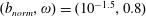
 $$\begin{eqnarray}{\mathcal{L}}=E(T)-\langle \boldsymbol{u}^{\ast },\unicode[STIX]{x2202}_{t}\boldsymbol{u}^{\prime }-L(\boldsymbol{U})\boldsymbol{u}^{\prime }-\boldsymbol{u}^{\prime }\boldsymbol{\cdot }\unicode[STIX]{x1D735}\boldsymbol{u}^{\prime }-\boldsymbol{f}^{\prime }\rangle -(\unicode[STIX]{x1D706},\Vert \boldsymbol{u}_{B}\Vert _{b}^{2}-b_{norm}^{2}),\end{eqnarray}$$
where the first term is the final energy to be maximized; the secondary term is a constraint that the perturbation satisfies (2.4) and
 $\boldsymbol{u}^{\ast }$
is an adjoint velocity vector; the last term constrains the
$\boldsymbol{u}^{\ast }$
is an adjoint velocity vector; the last term constrains the
 $b$
-norm of the inflow perturbation as a prescribed value
$b$
-norm of the inflow perturbation as a prescribed value
 $b_{norm}$
and
$b_{norm}$
and
 $\unicode[STIX]{x1D706}$
is a Lagrangian multiplier.
$\unicode[STIX]{x1D706}$
is a Lagrangian multiplier.
Through integration by parts, the second term can be reformulated as
 $$\begin{eqnarray}\displaystyle & & \displaystyle -\langle \boldsymbol{u}^{\ast },\unicode[STIX]{x2202}_{t}\boldsymbol{u}^{\prime }-L(\boldsymbol{U})\boldsymbol{u}^{\prime }-\boldsymbol{u}^{\prime }\boldsymbol{\cdot }\unicode[STIX]{x1D735}\boldsymbol{u}^{\prime }-\boldsymbol{f}^{\prime }\rangle =-T^{-1}(\boldsymbol{u}_{T}^{\ast },\boldsymbol{u}_{T}^{\prime })+\langle \boldsymbol{u}^{\prime },\unicode[STIX]{x2202}_{t}\boldsymbol{u}^{\ast }+L^{\ast }(\boldsymbol{U})\boldsymbol{u}^{\ast }\rangle \nonumber\\ \displaystyle & & \displaystyle \qquad \quad +\langle \boldsymbol{u}^{\prime },\boldsymbol{u}^{\prime }\boldsymbol{\cdot }\unicode[STIX]{x1D735}\boldsymbol{u}^{\ast }\rangle +\,\langle \boldsymbol{u}^{\prime },\boldsymbol{s}(2\boldsymbol{s}\boldsymbol{\cdot }\boldsymbol{U}+\boldsymbol{s}\boldsymbol{\cdot }\boldsymbol{u}^{\prime })(\boldsymbol{u}^{\ast },k\boldsymbol{s})\rangle \nonumber\\ \displaystyle & & \displaystyle \qquad \quad +\,\{\boldsymbol{n},-\boldsymbol{u}(\boldsymbol{u}^{\prime }\boldsymbol{\cdot }\boldsymbol{u}^{\ast })+\boldsymbol{u}^{\prime }p^{\ast }-\boldsymbol{u}^{\ast }p+Re^{-1}(\unicode[STIX]{x1D735}\boldsymbol{u}^{\prime }\boldsymbol{\cdot }\boldsymbol{u}^{\ast }-\unicode[STIX]{x1D735}\boldsymbol{u}^{\ast }\boldsymbol{\cdot }\boldsymbol{u}^{\prime })\},\end{eqnarray}$$
where
 $p^{\ast }$
is the adjoint pressure,
$p^{\ast }$
is the adjoint pressure,
 $\boldsymbol{u}_{T}$
(or
$\boldsymbol{u}_{T}$
(or
 $\boldsymbol{u}_{T}^{\ast }$
) is the velocity (or adjoint velocity) at time
$\boldsymbol{u}_{T}^{\ast }$
) is the velocity (or adjoint velocity) at time
 $T$
,
$T$
,
 $\boldsymbol{n}$
is the unit outward norm on the boundary
$\boldsymbol{n}$
is the unit outward norm on the boundary
 $\unicode[STIX]{x2202}\unicode[STIX]{x1D6FA}$
and
$\unicode[STIX]{x2202}\unicode[STIX]{x1D6FA}$
and
 $L^{\ast }$
is the adjoint operator of
$L^{\ast }$
is the adjoint operator of
 $L$
, depending on the base flow and acting on the adjoint variables. This adjoint operator has been extensively investigated in non-normality, receptivity, sensitivity and flow control studies.
$L$
, depending on the base flow and acting on the adjoint variables. This adjoint operator has been extensively investigated in non-normality, receptivity, sensitivity and flow control studies.
Setting the first variation of the Lagrangian with respect to
 $\boldsymbol{u}^{\prime }$
to zero, an adjoint equation is obtained,
$\boldsymbol{u}^{\prime }$
to zero, an adjoint equation is obtained,
 $$\begin{eqnarray}\unicode[STIX]{x2202}_{t}\boldsymbol{u}^{\ast }+\boldsymbol{u}\boldsymbol{\cdot }\unicode[STIX]{x1D735}\boldsymbol{u}^{\ast }-\unicode[STIX]{x1D735}\boldsymbol{u}\boldsymbol{\cdot }\boldsymbol{u}^{\ast }-\unicode[STIX]{x1D735}p^{\ast }+Re^{-1}\unicode[STIX]{x1D6FB}^{2}\boldsymbol{u}^{\ast }+2k\boldsymbol{s}\boldsymbol{\cdot }\boldsymbol{u}(\boldsymbol{s},\boldsymbol{u}^{\ast })\boldsymbol{s}=0\quad \text{with}~\unicode[STIX]{x1D735}\boldsymbol{\cdot }\boldsymbol{u}^{\ast }=0.\end{eqnarray}$$
The adjoint variables, which are used to calculate the optimal perturbations as detailed in the next section, can be obtained by integrating this equation, which requires the full developing history of
 $\boldsymbol{u}$
. Since
$\boldsymbol{u}$
. Since
 $\boldsymbol{u}=\boldsymbol{U}+\boldsymbol{u}^{\prime }$
and
$\boldsymbol{u}=\boldsymbol{U}+\boldsymbol{u}^{\prime }$
and
 $\boldsymbol{U}$
is steady, the perturbation velocity has to be saved at every step when integrating (2.4). Therefore large memory or space (
$\boldsymbol{U}$
is steady, the perturbation velocity has to be saved at every step when integrating (2.4). Therefore large memory or space (
 ${\sim}10^{4}$
GB in the present case) is required when solving the adjoint. Note that this constraint on memory can be mitigated by implementing a checkpointing scheme at the cost of extra calls of equations (2.4) (Schanen et al.
Reference Schanen, Marin, Zhang and Anitescu2016). Considering the sign of the viscous term and the time derivative term of this adjoint equation, it should be integrated backwards from
${\sim}10^{4}$
GB in the present case) is required when solving the adjoint. Note that this constraint on memory can be mitigated by implementing a checkpointing scheme at the cost of extra calls of equations (2.4) (Schanen et al.
Reference Schanen, Marin, Zhang and Anitescu2016). Considering the sign of the viscous term and the time derivative term of this adjoint equation, it should be integrated backwards from
 $t=T$
to
$t=T$
to
 $t=0$
. The initial condition of the adjoint equation,
$t=0$
. The initial condition of the adjoint equation,
 $\boldsymbol{u}_{T}^{\ast }=2TW\boldsymbol{u}_{T}^{\prime }$
, can be obtained by setting the first variation of the Lagrangian to
$\boldsymbol{u}_{T}^{\ast }=2TW\boldsymbol{u}_{T}^{\prime }$
, can be obtained by setting the first variation of the Lagrangian to
 $\boldsymbol{u}_{T}^{\prime }$
to zero.
$\boldsymbol{u}_{T}^{\prime }$
to zero.
On both the inflow and far-field boundaries, zero Dirichlet and computed Neumann conditions are used for adjoint velocity and pressure, respectively; on the outflow, a mixed velocity boundary condition
 $Re^{-1}\unicode[STIX]{x2202}_{\boldsymbol{n}}\boldsymbol{u}^{\ast }+\boldsymbol{n}\boldsymbol{\cdot }\boldsymbol{u}\boldsymbol{u}^{\ast }=0$
and a zero Dirichlet pressure condition are implemented (Mao et al.
Reference Mao, Blackburn and Sherwin2013); on the inflow boundary, Dirichlet and computed Neumann conditions are used for adjoint velocity and pressure terms, respectively. The choice of boundary conditions ensures that the boundary term, i.e. the last one in (2.16), is zero on all the boundaries except on the inflow boundary.
$Re^{-1}\unicode[STIX]{x2202}_{\boldsymbol{n}}\boldsymbol{u}^{\ast }+\boldsymbol{n}\boldsymbol{\cdot }\boldsymbol{u}\boldsymbol{u}^{\ast }=0$
and a zero Dirichlet pressure condition are implemented (Mao et al.
Reference Mao, Blackburn and Sherwin2013); on the inflow boundary, Dirichlet and computed Neumann conditions are used for adjoint velocity and pressure terms, respectively. The choice of boundary conditions ensures that the boundary term, i.e. the last one in (2.16), is zero on all the boundaries except on the inflow boundary.
2.5 Gradient of the Lagrangian
The variation of
 ${\mathcal{L}}$
with respect to the inflow perturbation term
${\mathcal{L}}$
with respect to the inflow perturbation term
 $\boldsymbol{u}_{B}$
is
$\boldsymbol{u}_{B}$
is
 $$\begin{eqnarray}\unicode[STIX]{x1D6FF}{\mathcal{L}}(\unicode[STIX]{x1D6FF}\boldsymbol{u}_{B})=[\boldsymbol{g}-2\unicode[STIX]{x1D706}\boldsymbol{u}_{B},\unicode[STIX]{x1D6FF}\boldsymbol{u}_{B}],\quad \text{where}~\boldsymbol{g}=T^{-1}\int _{0}^{T}(p^{\ast }\boldsymbol{n}-Re^{-1}\unicode[STIX]{x1D735}_{\boldsymbol{n}}\boldsymbol{u}^{\ast })G\,\text{d}t.\end{eqnarray}$$
Then the gradient of the Lagrangian with respect to
 $\boldsymbol{u}_{B}$
can be expressed as
$\boldsymbol{u}_{B}$
can be expressed as
 $$\begin{eqnarray}\unicode[STIX]{x1D735}_{\boldsymbol{u}_{B}}{\mathcal{L}}=\boldsymbol{g}-2\unicode[STIX]{x1D706}\boldsymbol{u}_{B}.\end{eqnarray}$$
Since the second term on the right-hand side of the equality does not change the form of
 $\boldsymbol{u}_{B}$
, it will be omitted in the following derivations. The first term can be decomposed into two parts, one parallel with
$\boldsymbol{u}_{B}$
, it will be omitted in the following derivations. The first term can be decomposed into two parts, one parallel with
 $\boldsymbol{u}_{B}$
and the other normal to
$\boldsymbol{u}_{B}$
and the other normal to
 $\boldsymbol{u}_{B}$
, by projecting
$\boldsymbol{u}_{B}$
, by projecting
 $\boldsymbol{g}$
onto
$\boldsymbol{g}$
onto
 $\boldsymbol{u}_{B}$
,
$\boldsymbol{u}_{B}$
,
 $$\begin{eqnarray}\boldsymbol{g}=c\boldsymbol{u}_{B}+d\tilde{\boldsymbol{g}},\end{eqnarray}$$
where
 $\tilde{\boldsymbol{g}}$
satisfies
$\tilde{\boldsymbol{g}}$
satisfies
 $[\tilde{\boldsymbol{g}},\boldsymbol{u}_{B}]=0$
; both
$[\tilde{\boldsymbol{g}},\boldsymbol{u}_{B}]=0$
; both
 $\boldsymbol{u}_{B}$
and
$\boldsymbol{u}_{B}$
and
 $\tilde{\boldsymbol{g}}$
are normalized to have norm
$\tilde{\boldsymbol{g}}$
are normalized to have norm
 $b_{norm}$
;
$b_{norm}$
;
 $c$
and
$c$
and
 $d$
are scale coefficients.
$d$
are scale coefficients.
When optimizing the boundary perturbation iteratively from step
 $n$
to
$n$
to
 $n+1$
,
$n+1$
,
 $\boldsymbol{u}_{B}$
is updated following the direction
$\boldsymbol{u}_{B}$
is updated following the direction
 $\tilde{\boldsymbol{g}}$
,
$\tilde{\boldsymbol{g}}$
,
 $$\begin{eqnarray}\boldsymbol{u}_{B}^{n+1}=b_{norm}\frac{\boldsymbol{u}_{B}^{n}+\unicode[STIX]{x1D6FC}\tilde{\boldsymbol{g}}}{\Vert \boldsymbol{u}_{B}^{n}+\unicode[STIX]{x1D6FC}\tilde{\boldsymbol{g}}\Vert _{b}}=\frac{\boldsymbol{u}_{B}^{n}+\unicode[STIX]{x1D6FC}\tilde{\boldsymbol{g}}}{\sqrt{1+\unicode[STIX]{x1D6FC}^{2}}},\end{eqnarray}$$
where
 $\unicode[STIX]{x1D6FC}$
is a step length. When the update of the perturbation
$\unicode[STIX]{x1D6FC}$
is a step length. When the update of the perturbation
 $\boldsymbol{u}_{B}^{n+1}-\boldsymbol{u}_{B}^{n}$
is small enough compared with
$\boldsymbol{u}_{B}^{n+1}-\boldsymbol{u}_{B}^{n}$
is small enough compared with
 $\boldsymbol{u}_{B}^{n}$
, there is an optimal value of
$\boldsymbol{u}_{B}^{n}$
, there is an optimal value of
 $\unicode[STIX]{x1D6FC}$
, which is the ratio of
$\unicode[STIX]{x1D6FC}$
, which is the ratio of
 $d$
and
$d$
and
 $c$
, as proved in the appendix A.
$c$
, as proved in the appendix A.
3 Convergence and discretization

Figure 2. Spectral elements in the
 $x$
–
$x$
–
 $r$
plane for (a) the full domain and (b) a subdomain surrounding the disc and the inflow boundary.
$r$
plane for (a) the full domain and (b) a subdomain surrounding the disc and the inflow boundary.
A spectral element method is used to discretize the governing equations, e.g. the NS equations and the adjoint equation (Karniadakis & Sherwin Reference Karniadakis and Sherwin2005). A decomposition of the domain into 4730 spectral elements is shown in figure 2(a), while the subdomain around the actuator disc is illustrated in figure 2(b).
The computational domain spans from
 $x=-3$
to
$x=-3$
to
 $x=60$
and
$x=60$
and
 $r=0$
to
$r=0$
to
 $r=35$
in streamwise and radial directions, respectively. The 2-D domain is used in the calculation of the base flow, while in 3-D computations, a Fourier decomposition is adopted to discretize the azimuthal direction. For all results and computations shown in the following, 64 Fourier modes are employed.
$r=35$
in streamwise and radial directions, respectively. The 2-D domain is used in the calculation of the base flow, while in 3-D computations, a Fourier decomposition is adopted to discretize the azimuthal direction. For all results and computations shown in the following, 64 Fourier modes are employed.

Figure 3. Contours of the streamwise component of
 $\boldsymbol{s}$
(see (2.7)) and the base flow velocity
$\boldsymbol{s}$
(see (2.7)) and the base flow velocity
 $\boldsymbol{U}$
at
$\boldsymbol{U}$
at
 $Re=1000$
in (a) and (b), respectively.
$Re=1000$
in (a) and (b), respectively.
The actuator disc is located at
 $x=0$
, with a streamwise thickness
$x=0$
, with a streamwise thickness
 $\unicode[STIX]{x0394}x=0.02$
and a unit radius. The streamwise vector
$\unicode[STIX]{x0394}x=0.02$
and a unit radius. The streamwise vector
 $\boldsymbol{s}$
used to define the disc model in (2.7) has unit value inside the disc and decays to zero outside the disc, as shown in figure 3(a). The 2-D base flow used in calculating the optimal inflow noise is presented in figure 3(b). Here the Reynolds number is set to
$\boldsymbol{s}$
used to define the disc model in (2.7) has unit value inside the disc and decays to zero outside the disc, as shown in figure 3(a). The 2-D base flow used in calculating the optimal inflow noise is presented in figure 3(b). Here the Reynolds number is set to
 $Re=1000$
, which will be used in the following unless otherwise specified. The deficit of streamwise velocity in the wake can be clearly observed. In a separate global stability study (Mao & Blackburn Reference Mao and Blackburn2014), it was verified that this base flow is asymptotically stable and does not support absolute instabilities.
$Re=1000$
, which will be used in the following unless otherwise specified. The deficit of streamwise velocity in the wake can be clearly observed. In a separate global stability study (Mao & Blackburn Reference Mao and Blackburn2014), it was verified that this base flow is asymptotically stable and does not support absolute instabilities.
The weight function
 $W$
(see (2.14)) is defined as
$W$
(see (2.14)) is defined as
 $$\begin{eqnarray}W(\boldsymbol{x})=\left\{\begin{array}{@{}ll@{}}1\quad & \text{for}~x<15,\\ \exp (-(x-15)^{2})\quad & \text{for}~x\geqslant 15,\end{array}\right.\end{eqnarray}$$
which filters out the perturbations far downstream of the disc in order to isolate a ‘region of interest’ where the resolution is concentrated. A final time
 $T=20$
, which is enough for the inflow noise to reach the boundary of the region of interest, is adopted throughout this work unless otherwise stated.
$T=20$
, which is enough for the inflow noise to reach the boundary of the region of interest, is adopted throughout this work unless otherwise stated.
In each element, a spectral method is used to further decompose the element to a
 $({\mathcal{P}}+1)\times ({\mathcal{P}}+1)$
grid, where
$({\mathcal{P}}+1)\times ({\mathcal{P}}+1)$
grid, where
 ${\mathcal{P}}$
represents a polynomial order and can be used to refine the resolution in the convergence test (Karniadakis & Sherwin Reference Karniadakis and Sherwin2005). The dependence of the maximum energy growth
${\mathcal{P}}$
represents a polynomial order and can be used to refine the resolution in the convergence test (Karniadakis & Sherwin Reference Karniadakis and Sherwin2005). The dependence of the maximum energy growth
 $E$
with respect to
$E$
with respect to
 ${\mathcal{P}}$
is illustrated in table 1. It is seen that
${\mathcal{P}}$
is illustrated in table 1. It is seen that
 $E$
has converged to within a tolerance of 1 % at
$E$
has converged to within a tolerance of 1 % at
 ${\mathcal{P}}=5$
. In the following studies
${\mathcal{P}}=5$
. In the following studies
 ${\mathcal{P}}=5$
will be applied.
${\mathcal{P}}=5$
will be applied.
Table 1. Convergence of the perturbation energy
 $E$
with respect to the polynomial order
$E$
with respect to the polynomial order
 ${\mathcal{P}}$
in the spectral element method and time step
${\mathcal{P}}$
in the spectral element method and time step
 $\text{d}t$
at
$\text{d}t$
at
 $b$
-norm
$b$
-norm
 $10^{-3.5}$
, frequency
$10^{-3.5}$
, frequency
 $\unicode[STIX]{x1D714}=2$
, final time
$\unicode[STIX]{x1D714}=2$
, final time
 $T=20$
and Reynolds number
$T=20$
and Reynolds number
 $Re=1000$
.
$Re=1000$
.

4 Results and discussion
4.1 Optimal perturbation energy

Figure 4. Contours of the logarithm of the perturbation energy
 $\text{log}(E)$
. The points marked as ‘a’, ‘b’, ‘c’ and ‘d’ are studied in detail in the following. The final time and Reynolds number are set to
$\text{log}(E)$
. The points marked as ‘a’, ‘b’, ‘c’ and ‘d’ are studied in detail in the following. The final time and Reynolds number are set to
 $T=20$
and
$T=20$
and
 $Re=1000$
, which will be used in the following unless otherwise specified.
$Re=1000$
, which will be used in the following unless otherwise specified.
The optimal perturbation energy is illustrated in figure 4. When the inflow perturbation is small (small values of
 $b_{norm}$
), the contour lines of
$b_{norm}$
), the contour lines of
 $\text{log}(E)$
are evenly distributed with respect to
$\text{log}(E)$
are evenly distributed with respect to
 $\text{log}(b_{norm})$
, indicating that the gain
$\text{log}(b_{norm})$
, indicating that the gain
 $\sqrt{E}/b_{norm}$
is independent of
$\sqrt{E}/b_{norm}$
is independent of
 $b_{norm}$
and that the perturbation dynamics is linear. As the inflow perturbation becomes larger, the contour lines become sparser, indicating that
$b_{norm}$
and that the perturbation dynamics is linear. As the inflow perturbation becomes larger, the contour lines become sparser, indicating that
 $\sqrt{E/}b_{norm}$
reduces owing to the nonlinear interaction of the perturbation with itself.
$\sqrt{E/}b_{norm}$
reduces owing to the nonlinear interaction of the perturbation with itself.
At the smallest inflow perturbation magnitude considered,
 $b_{norm}=10^{-4}$
, the final energy maximizes at
$b_{norm}=10^{-4}$
, the final energy maximizes at
 $\unicode[STIX]{x1D714}=2$
. This optimal frequency gradually reduces to
$\unicode[STIX]{x1D714}=2$
. This optimal frequency gradually reduces to
 $\unicode[STIX]{x1D714}=0.8$
as the inflow magnitude increases to
$\unicode[STIX]{x1D714}=0.8$
as the inflow magnitude increases to
 $b_{norm}=10^{-1.5}$
. It is worth noting that
$b_{norm}=10^{-1.5}$
. It is worth noting that
 $\unicode[STIX]{x1D714}=0.8$
corresponds to a Strouhal number (based on the turbine diameter and free-stream velocity)
$\unicode[STIX]{x1D714}=0.8$
corresponds to a Strouhal number (based on the turbine diameter and free-stream velocity)
 $St=\unicode[STIX]{x1D714}/\unicode[STIX]{x03C0}=0.25$
. This Strouhal number will be discussed further in § 4.5.
$St=\unicode[STIX]{x1D714}/\unicode[STIX]{x03C0}=0.25$
. This Strouhal number will be discussed further in § 4.5.

Figure 5. Logarithm of the perturbation energy
 $\text{log}(E)$
at
$\text{log}(E)$
at
 $b_{norm}=10^{-2}$
. The dotted lines mark the inflow perturbation frequency
$b_{norm}=10^{-2}$
. The dotted lines mark the inflow perturbation frequency
 $\unicode[STIX]{x1D714}$
at which
$\unicode[STIX]{x1D714}$
at which
 $E$
reaches maximum.
$E$
reaches maximum.
Then the final time is varied from the default value
 $T=20$
with the inflow perturbation magnitude fixed at
$T=20$
with the inflow perturbation magnitude fixed at
 $b_{norm}=10^{-2}$
. As shown in figure 5, for increasing
$b_{norm}=10^{-2}$
. As shown in figure 5, for increasing
 $T$
, the frequency
$T$
, the frequency
 $\unicode[STIX]{x1D714}$
at which the perturbation energy maximizes reduces. Since the inflow perturbation can be convected further downstream at higher
$\unicode[STIX]{x1D714}$
at which the perturbation energy maximizes reduces. Since the inflow perturbation can be convected further downstream at higher
 $T$
, this observation indicates that the lower-frequency inflow perturbation can generate larger impacts to the far wake.
$T$
, this observation indicates that the lower-frequency inflow perturbation can generate larger impacts to the far wake.
4.2 Optimal inflow perturbation

Figure 6. (a–d) Streamwise components of the optimal inflow perturbation at
 $(b_{norm},\unicode[STIX]{x1D714})=(10^{-4},2)$
,
$(b_{norm},\unicode[STIX]{x1D714})=(10^{-4},2)$
,
 $(10^{-3},1.5)$
,
$(10^{-3},1.5)$
,
 $(10^{-2},1)$
and
$(10^{-2},1)$
and
 $(10^{-1.5},0.8)$
, respectively, as marked in figure 4. (e,f) Radial and azimuthal components of the optimal inflow velocity at
$(10^{-1.5},0.8)$
, respectively, as marked in figure 4. (e,f) Radial and azimuthal components of the optimal inflow velocity at
 $(b_{norm},\unicode[STIX]{x1D714})=(10^{-1.5},0.8)$
.
$(b_{norm},\unicode[STIX]{x1D714})=(10^{-1.5},0.8)$
.
The distribution of the optimal inflow perturbations is presented in figure 6. Here Cartesian coordinates
 $(x,y,z)$
are adopted and
$(x,y,z)$
are adopted and
 $y=r\,\text{cos}(\unicode[STIX]{x1D703})$
and
$y=r\,\text{cos}(\unicode[STIX]{x1D703})$
and
 $z=r\,\text{sin}(\unicode[STIX]{x1D703})$
denote the vertical and lateral coordinates, respectively. Clearly at small enough perturbation magnitudes, the optimal solution consists of a single azimuthal wave with wavenumber
$z=r\,\text{sin}(\unicode[STIX]{x1D703})$
denote the vertical and lateral coordinates, respectively. Clearly at small enough perturbation magnitudes, the optimal solution consists of a single azimuthal wave with wavenumber
 $m=1$
. This is because the base flow is homogenous in the azimuthal direction, and in the linear limit, waves with different azimuthal wavenumbers are orthogonal and therefore the linearly optimal perturbation takes the form of the most energetic azimuthal mode. As the magnitude increases, the distribution becomes more complicated and can be interpreted as a superposition of multiple azimuthal waves, even though the mode
$m=1$
. This is because the base flow is homogenous in the azimuthal direction, and in the linear limit, waves with different azimuthal wavenumbers are orthogonal and therefore the linearly optimal perturbation takes the form of the most energetic azimuthal mode. As the magnitude increases, the distribution becomes more complicated and can be interpreted as a superposition of multiple azimuthal waves, even though the mode
 $m=1$
is still dominant. The optimal perturbation is mainly in the streamwise and radial directions while the component in the azimuthal direction is smaller but more localized (see figure 6
d–f). All the optimal inflow perturbations are located within an annular region with a unit radius. Such structures can be convected by the base flow to the tip region of the turbine. In this region the shear maximizes (see figure 3
b) and acts as an amplifier to upstream noise, as will be discussed later. It is worth noting that the azimuthal orientation of the optimal perturbation shown in figure 6 is random and rotating the inflow perturbation in the azimuthal direction does not change the results.
$m=1$
is still dominant. The optimal perturbation is mainly in the streamwise and radial directions while the component in the azimuthal direction is smaller but more localized (see figure 6
d–f). All the optimal inflow perturbations are located within an annular region with a unit radius. Such structures can be convected by the base flow to the tip region of the turbine. In this region the shear maximizes (see figure 3
b) and acts as an amplifier to upstream noise, as will be discussed later. It is worth noting that the azimuthal orientation of the optimal perturbation shown in figure 6 is random and rotating the inflow perturbation in the azimuthal direction does not change the results.
4.3 Wake meandering

Figure 7. Iso-surfaces of streamwise velocity
 $0.3$
,
$0.3$
,
 $0.5$
and
$0.5$
and
 $0.8$
at
$0.8$
at
 $(b_{norm},\unicode[STIX]{x1D714})=(10^{-4},2)$
,
$(b_{norm},\unicode[STIX]{x1D714})=(10^{-4},2)$
,
 $(10^{-3},1.5)$
,
$(10^{-3},1.5)$
,
 $(10^{-2},1)$
and
$(10^{-2},1)$
and
 $(10^{-1.5},0.8)$
for (a), (b), (c) and (d), respectively (see the points marked in figure 4).
$(10^{-1.5},0.8)$
for (a), (b), (c) and (d), respectively (see the points marked in figure 4).
The corresponding perturbed velocities are illustrated in figure 7. At
 $b_{norm}=10^{-4}$
, the wake flow is almost columnar and unperturbed. As the perturbation magnitude increases, a significant wake meandering motion appears in the wake and spreads upstream. This observation suggests that the wake meandering observed in wind farm fields is related to large-scale (the same size as the turbine rotor) and low-frequency (Strouhal number below 0.25) atmospheric eddies, which can be considered as a component of atmospheric turbulence. This meandering affects the performance of downstream turbines in terms of both energy output and fatigue loadings. Different from the oscillations induced by tip and root vortices, which are concentrated in the near wake and wake centre, respectively, the present wake oscillation occurs mainly in the far field and expands radially along the streamwise direction.
$b_{norm}=10^{-4}$
, the wake flow is almost columnar and unperturbed. As the perturbation magnitude increases, a significant wake meandering motion appears in the wake and spreads upstream. This observation suggests that the wake meandering observed in wind farm fields is related to large-scale (the same size as the turbine rotor) and low-frequency (Strouhal number below 0.25) atmospheric eddies, which can be considered as a component of atmospheric turbulence. This meandering affects the performance of downstream turbines in terms of both energy output and fatigue loadings. Different from the oscillations induced by tip and root vortices, which are concentrated in the near wake and wake centre, respectively, the present wake oscillation occurs mainly in the far field and expands radially along the streamwise direction.

Figure 8. (a) Fluctuation of the streamwise velocity and (b) power spectrum of the spanwise velocity along the axis of the disc at
 $\unicode[STIX]{x1D714}=0.8$
and
$\unicode[STIX]{x1D714}=0.8$
and
 $b_{norm}=10^{-1.5}$
.
$b_{norm}=10^{-1.5}$
.
The oscillation of the streamwise velocity along the turbine axis is presented in figure 8(a). At more downstream locations, where the perturbations are sufficiently amplified, the oscillation becomes more complex and the magnitude increases rapidly. At
 $x=10$
(five diameters downstream of the turbine), the oscillation magnitude reaches a value of more than 60 % of the free-stream wind speed. Considering that the inflow perturbation has a maximum velocity of approximately 6 % of free-stream wind speed (see figure 6
d), it is amplified by approximately one order of magnitude in the wake.
$x=10$
(five diameters downstream of the turbine), the oscillation magnitude reaches a value of more than 60 % of the free-stream wind speed. Considering that the inflow perturbation has a maximum velocity of approximately 6 % of free-stream wind speed (see figure 6
d), it is amplified by approximately one order of magnitude in the wake.
To better illustrate the oscillation frequency of the wake, the power spectrum of the spanwise velocity at
 $t>30$
(after the transient period shown in figure 8
a) is plotted in figure 8(b). In this optimally perturbed flow, over the streamwise locations considered, the dominant frequency of the oscillation is the same as the inflow frequency, while harmonics of this dominant frequency are activated further downstream. This observation indicates that the frequency of wake meandering can be constant (determined by the frequency of the most energetic perturbation in the free-stream turbulence), as observed in experiments by Okulov et al. (Reference Okulov, Naumov, Mikkelsen, Kabardin and Sørensen2014). These authors focused on various operating conditions of the turbine instead of the free-stream turbulence conditions, but suggested that the effect of free-stream turbulence on the frequency of the wake oscillation deserves further investigations.
$t>30$
(after the transient period shown in figure 8
a) is plotted in figure 8(b). In this optimally perturbed flow, over the streamwise locations considered, the dominant frequency of the oscillation is the same as the inflow frequency, while harmonics of this dominant frequency are activated further downstream. This observation indicates that the frequency of wake meandering can be constant (determined by the frequency of the most energetic perturbation in the free-stream turbulence), as observed in experiments by Okulov et al. (Reference Okulov, Naumov, Mikkelsen, Kabardin and Sørensen2014). These authors focused on various operating conditions of the turbine instead of the free-stream turbulence conditions, but suggested that the effect of free-stream turbulence on the frequency of the wake oscillation deserves further investigations.

Figure 9. (a) The mean streamwise velocity
 $\bar{u}=\int _{0}^{T}\int _{0}^{2\unicode[STIX]{x03C0}}u\,\text{d}t\,\text{d}\unicode[STIX]{x1D703}/(2\unicode[STIX]{x03C0}T)$
. (b) Standard deviation of the streamwise velocity
$\bar{u}=\int _{0}^{T}\int _{0}^{2\unicode[STIX]{x03C0}}u\,\text{d}t\,\text{d}\unicode[STIX]{x1D703}/(2\unicode[STIX]{x03C0}T)$
. (b) Standard deviation of the streamwise velocity
 $\unicode[STIX]{x1D6E5}=(\int _{0}^{T}\int _{0}^{2\unicode[STIX]{x03C0}}(u-\bar{u})^{2}\,\text{d}t\,\text{d}\unicode[STIX]{x1D703}/(2\unicode[STIX]{x03C0}T))^{1/2}$
.
$\unicode[STIX]{x1D6E5}=(\int _{0}^{T}\int _{0}^{2\unicode[STIX]{x03C0}}(u-\bar{u})^{2}\,\text{d}t\,\text{d}\unicode[STIX]{x1D703}/(2\unicode[STIX]{x03C0}T))^{1/2}$
.
The wind power generation of downstream located wind turbines depends on the streamwise mean wind, which can be calculated as
 $\bar{u}=\int _{0}^{T}\int _{0}^{2\unicode[STIX]{x03C0}}u\,\text{d}t\,\text{d}\unicode[STIX]{x1D703}/(2\unicode[STIX]{x03C0}T)$
. This mean velocity is plotted in figure 9(a). It is noticed that in the present case the velocity deficit maximizes at around
$\bar{u}=\int _{0}^{T}\int _{0}^{2\unicode[STIX]{x03C0}}u\,\text{d}t\,\text{d}\unicode[STIX]{x1D703}/(2\unicode[STIX]{x03C0}T)$
. This mean velocity is plotted in figure 9(a). It is noticed that in the present case the velocity deficit maximizes at around
 $x=5$
, and then the velocity starts to recover in downstream. The velocity fluctuation, which is critical to the fatiguing loading on the turbine, can be evaluated using the velocity standard deviation
$x=5$
, and then the velocity starts to recover in downstream. The velocity fluctuation, which is critical to the fatiguing loading on the turbine, can be evaluated using the velocity standard deviation
 $\unicode[STIX]{x1D6E5}=(\int _{0}^{T}\int _{0}^{2\unicode[STIX]{x03C0}}(u-\bar{u})^{2}\,\text{d}t\,\text{d}\unicode[STIX]{x1D703}/(2\unicode[STIX]{x03C0}T))^{1/2}$
, as plotted in figure 9(b). The oscillation upstream of the actuator expresses the oscillating inflow noise. The maximum oscillation is located close to the region downstream of the turbine tip, even at the absence of tip vortices. Further downstream, the oscillation spreads radially, similar to the behaviour of the mean wind.
$\unicode[STIX]{x1D6E5}=(\int _{0}^{T}\int _{0}^{2\unicode[STIX]{x03C0}}(u-\bar{u})^{2}\,\text{d}t\,\text{d}\unicode[STIX]{x1D703}/(2\unicode[STIX]{x03C0}T))^{1/2}$
, as plotted in figure 9(b). The oscillation upstream of the actuator expresses the oscillating inflow noise. The maximum oscillation is located close to the region downstream of the turbine tip, even at the absence of tip vortices. Further downstream, the oscillation spreads radially, similar to the behaviour of the mean wind.
4.4 Mechanism of the wake meandering

Figure 10. Iso-surfaces of
 $\unicode[STIX]{x1D706}_{2}=-0.3$
at
$\unicode[STIX]{x1D706}_{2}=-0.3$
at
 $(b_{norm},\unicode[STIX]{x1D714})=$
 $(10^{-4},2)$
,
$(10^{-4},2)$
,
 $(10^{-3},1.5)$
,
$(10^{-3},1.5)$
,
 $(10^{-2},1)$
and
$(10^{-2},1)$
and
 $(10^{-1.5},0.8)$
from (a) to (d) as marked in figure 4. Grey lines denote vortex lines in the wake.
$(10^{-1.5},0.8)$
from (a) to (d) as marked in figure 4. Grey lines denote vortex lines in the wake.
To illustrate the mechanism of meandering, vortex structures in the wake flow identified by the iso-surface of
 $\unicode[STIX]{x1D706}_{2}=-0.3$
are shown in figure 10 (Jeong & Hussain Reference Jeong and Hussain1995). The grey lines represent typical vortex lines. Note that owing to the choice of final time in the optimization, i.e.
$\unicode[STIX]{x1D706}_{2}=-0.3$
are shown in figure 10 (Jeong & Hussain Reference Jeong and Hussain1995). The grey lines represent typical vortex lines. Note that owing to the choice of final time in the optimization, i.e.
 $T=20$
, perturbations introduced from the inflow boundary only reach approximately
$T=20$
, perturbations introduced from the inflow boundary only reach approximately
 $x\approx 15$
. Due to convective instabilities, axisymmetric vortex rings roll up from the shear in the near wake, where the inflow perturbation is amplified but has a trivial impact on the wake. Further downstream, the amplified inflow perturbations tilt and deform the vortex rings. This effect becomes stronger when the magnitude of the inflow perturbation increases. Here the vortex ring can be interpreted as large vortex structures in the turbine wake flow. If adopting other turbine models, e.g. the actuator line model, these structures can be segments of helical vortices. Therefore the wake meandering can be decomposed into two steps; the large-scale inflow perturbations are amplified by the shear in the wake, and then tilt the large coherent vortex structures in the wake to induce meandering.
$x\approx 15$
. Due to convective instabilities, axisymmetric vortex rings roll up from the shear in the near wake, where the inflow perturbation is amplified but has a trivial impact on the wake. Further downstream, the amplified inflow perturbations tilt and deform the vortex rings. This effect becomes stronger when the magnitude of the inflow perturbation increases. Here the vortex ring can be interpreted as large vortex structures in the turbine wake flow. If adopting other turbine models, e.g. the actuator line model, these structures can be segments of helical vortices. Therefore the wake meandering can be decomposed into two steps; the large-scale inflow perturbations are amplified by the shear in the wake, and then tilt the large coherent vortex structures in the wake to induce meandering.
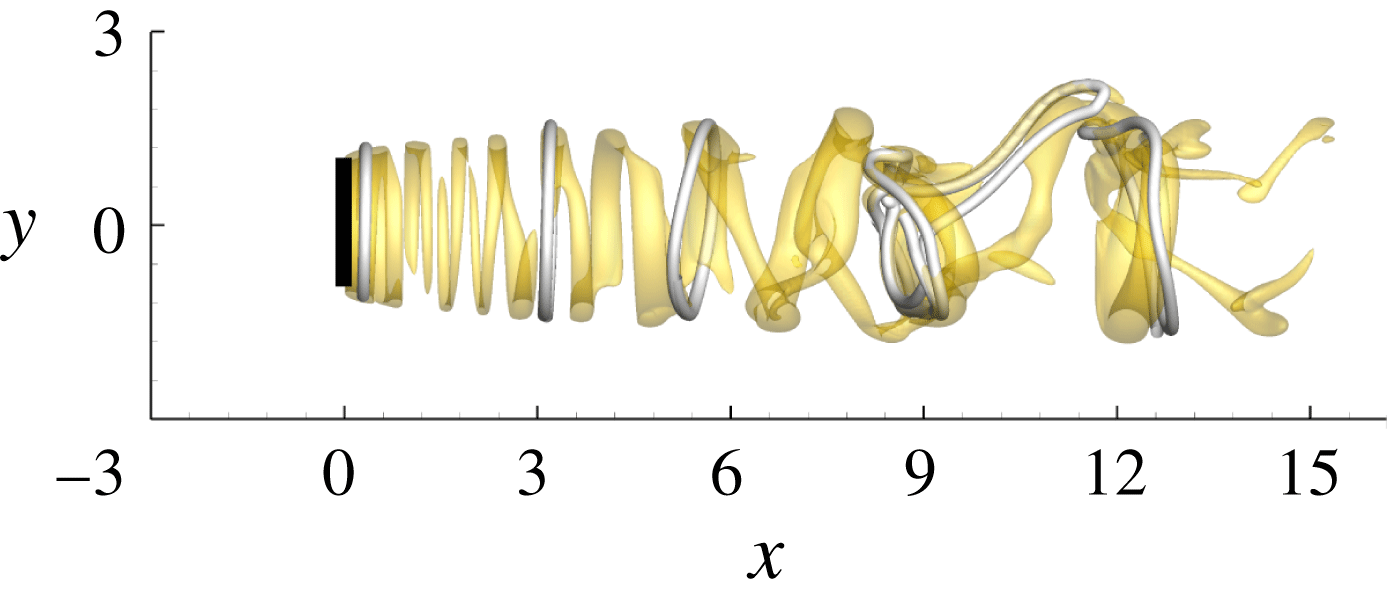
Figure 11. Iso-surfaces of
 $\unicode[STIX]{x1D706}_{2}=-0.3$
in the flow perturbed by random inflow disturbance at turbulent intensity 0.04. The grey lines denote vortex lines.
$\unicode[STIX]{x1D706}_{2}=-0.3$
in the flow perturbed by random inflow disturbance at turbulent intensity 0.04. The grey lines denote vortex lines.
To verify the role of inflow perturbations on wake meandering observed in the optimally perturbed flow, a random inflow perturbation with turbulent intensity 0.04 is then tested. In this randomly perturbed flow, the wake oscillation is also associated with the tilted vortex ring structures (see figure 11), as has been observed in the optimally perturbed flow in figure 10. The agreement of the randomly and optimally perturbed flow approves the mechanism of meandering reported above. This observation can be interpreted as that the optimal inflow perturbation is the most amplified component of a random disturbance and it has the most significant impact on the wake.
4.5 Reynolds number effect

Figure 12. Power spectrum of the streamwise velocity along the axis of the disc at
 $x=10$
. The inflow perturbation is random with azimuthal wavenumber
$x=10$
. The inflow perturbation is random with azimuthal wavenumber
 $m=1$
and turbulent intensity 0.04.
$m=1$
and turbulent intensity 0.04.
All the results reported above are obtained at
 $Re=1000$
. In this section, higher Reynolds numbers up to 8000 are tested to reveal the Reynolds number effect on wake meandering. Random inflow perturbations with azimuthal wavenumber
$Re=1000$
. In this section, higher Reynolds numbers up to 8000 are tested to reveal the Reynolds number effect on wake meandering. Random inflow perturbations with azimuthal wavenumber
 $m=1$
and turbulence intensity 0.04 are imposed as the inflow disturbance. Perturbations with other azimuthal wavenumbers will be energized due to the nonlinear perturbation dynamics.
$m=1$
and turbulence intensity 0.04 are imposed as the inflow disturbance. Perturbations with other azimuthal wavenumbers will be energized due to the nonlinear perturbation dynamics.
The power spectrum of the spanwise velocity at
 $x=10$
(five diameters downstream of the turbine) at various Reynolds numbers is shown in figure 12. At
$x=10$
(five diameters downstream of the turbine) at various Reynolds numbers is shown in figure 12. At
 $Re=1000$
, the dominant frequency in the wake is
$Re=1000$
, the dominant frequency in the wake is
 $\unicode[STIX]{x1D714}=1$
. This agrees well with the perturbation growth reported in figures 4 and 5. At
$\unicode[STIX]{x1D714}=1$
. This agrees well with the perturbation growth reported in figures 4 and 5. At
 $Re=3000$
, this dominant frequency reduces to around
$Re=3000$
, this dominant frequency reduces to around
 $\unicode[STIX]{x1D714}=0.5$
, and remains almost constant for higher
$\unicode[STIX]{x1D714}=0.5$
, and remains almost constant for higher
 $Re$
. Such an independence of the governing frequency on
$Re$
. Such an independence of the governing frequency on
 $Re$
suggests that in the real condition where the
$Re$
suggests that in the real condition where the
 $Re$
is much higher, the wake meandering would also occur at
$Re$
is much higher, the wake meandering would also occur at
 $\unicode[STIX]{x1D714}=0.5$
. It is further noticed that this frequency corresponds to a Strouhal number
$\unicode[STIX]{x1D714}=0.5$
. It is further noticed that this frequency corresponds to a Strouhal number
 $St=0.16$
, falling in the range 0.15–0.25 observed in experiments of wake meandering (Medici & Alfredsson Reference Medici and Alfredsson2008).
$St=0.16$
, falling in the range 0.15–0.25 observed in experiments of wake meandering (Medici & Alfredsson Reference Medici and Alfredsson2008).

Figure 13. Iso-surfaces of
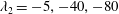 $\unicode[STIX]{x1D706}_{2}=-5,-40,-80$
at
$\unicode[STIX]{x1D706}_{2}=-5,-40,-80$
at
 $Re=3000$
, 5000 and 8000 from (a) to (c). The inflow perturbation is random with azimuthal wavenumber
$Re=3000$
, 5000 and 8000 from (a) to (c). The inflow perturbation is random with azimuthal wavenumber
 $m=1$
and turbulent intensity 0.04.
$m=1$
and turbulent intensity 0.04.
From figure 12, the high-frequency oscillations become stronger at higher
 $Re$
, which suggests a development of turbulence in the wake. The wake structures at
$Re$
, which suggests a development of turbulence in the wake. The wake structures at
 $Re=3000$
, 5000 and 8000 are then illustrated using iso-surfaces of
$Re=3000$
, 5000 and 8000 are then illustrated using iso-surfaces of
 $\unicode[STIX]{x1D706}_{2}$
in figure 13. In the near wake, the quasi-axisymmetric vortex rings can be observed in all the three cases. These large vortex structures are then tilted by the amplified inflow disturbance before breaking up to vortex filaments. Even though the wake flow becomes increasing turbulent as
$\unicode[STIX]{x1D706}_{2}$
in figure 13. In the near wake, the quasi-axisymmetric vortex rings can be observed in all the three cases. These large vortex structures are then tilted by the amplified inflow disturbance before breaking up to vortex filaments. Even though the wake flow becomes increasing turbulent as
 $Re$
increases, the dominant oscillation frequency is almost constant at
$Re$
increases, the dominant oscillation frequency is almost constant at
 $\unicode[STIX]{x1D714}=0.5$
, as shown in figure 12. These observations verify that the optimal inflow perturbation study at relatively low
$\unicode[STIX]{x1D714}=0.5$
, as shown in figure 12. These observations verify that the optimal inflow perturbation study at relatively low
 $Re$
reveals the mechanism and shed light on the understanding of wake meandering at high
$Re$
reveals the mechanism and shed light on the understanding of wake meandering at high
 $Re$
.
$Re$
.
5 Conclusion
For the first time in perturbation analyses, a 3-D nonlinear optimal perturbation in the free stream (inflow boundary) is calculated. The numerical algorithm involves solving the decomposed NS equations and the adjoint. Similarly with existing algorithms to calculate optimal initial perturbations, the full perturbation history has to be saved to solve the adjoint. An optimal step length in the linear sense is obtained without any additional calls of the governing equations and therefore significantly reduces the computational cost, as compared to line search methods.
The algorithm is applied to flow past a wind turbine modelled as a circular disc at
 $Re=1000$
, to investigate the wake meandering induced by inflow turbulent eddies. Over the parameters considered, the most energetic inflow perturbation is dominated by an azimuthal Fourier mode with wavenumber
$Re=1000$
, to investigate the wake meandering induced by inflow turbulent eddies. Over the parameters considered, the most energetic inflow perturbation is dominated by an azimuthal Fourier mode with wavenumber
 $m=1$
. During the development of the optimal inflow perturbation, its main structures are convected by the base flow to the region around the turbine tip, where the shear maximizes and acts as an amplifier to upstream perturbations. In the region further downstream, the perturbation induces significant oscillations of the wake flow. At five turbine diameters downstream of the disc, the centre velocity oscillates at a magnitude approximately 60 % of the free-stream velocity, when the optimal inflow perturbation is 6 % of the free-stream wind speed. The calculation therefore contributes to evaluate the upper limit of the magnitude of meandering. For this optimally perturbed flow, the maximum velocity deficit occurs on the axis five radii downstream of the disc, while the maximum oscillation appears in the region downstream of the tip of the disc, even in the absence of tip vortices.
$m=1$
. During the development of the optimal inflow perturbation, its main structures are convected by the base flow to the region around the turbine tip, where the shear maximizes and acts as an amplifier to upstream perturbations. In the region further downstream, the perturbation induces significant oscillations of the wake flow. At five turbine diameters downstream of the disc, the centre velocity oscillates at a magnitude approximately 60 % of the free-stream velocity, when the optimal inflow perturbation is 6 % of the free-stream wind speed. The calculation therefore contributes to evaluate the upper limit of the magnitude of meandering. For this optimally perturbed flow, the maximum velocity deficit occurs on the axis five radii downstream of the disc, while the maximum oscillation appears in the region downstream of the tip of the disc, even in the absence of tip vortices.
When the perturbation magnitude is small enough, the inflow perturbation with frequency
 $\unicode[STIX]{x1D714}=2$
is the most amplified one. As the magnitude of the inflow perturbations increases, this dominant frequency reduces to
$\unicode[STIX]{x1D714}=2$
is the most amplified one. As the magnitude of the inflow perturbations increases, this dominant frequency reduces to
 $\unicode[STIX]{x1D714}=0.8$
. The frequency of the wake meandering matches that of the optimal inflow perturbation, confirming that the turbine wake flow acts as an amplifier to upstream noise. Then at higher Reynolds number, the meandering frequency further reduces to
$\unicode[STIX]{x1D714}=0.8$
. The frequency of the wake meandering matches that of the optimal inflow perturbation, confirming that the turbine wake flow acts as an amplifier to upstream noise. Then at higher Reynolds number, the meandering frequency further reduces to
 $\unicode[STIX]{x1D714}=0.5$
and presents a Reynolds number independence over the range of parameters tested. This frequency corresponds to a Strouhal number
$\unicode[STIX]{x1D714}=0.5$
and presents a Reynolds number independence over the range of parameters tested. This frequency corresponds to a Strouhal number
 $St=0.16$
, agreeing well with experimental observations (Medici & Alfredsson Reference Medici and Alfredsson2008).
$St=0.16$
, agreeing well with experimental observations (Medici & Alfredsson Reference Medici and Alfredsson2008).
Owing to the optimality of the inflow condition, the development of large-scale atmospheric eddies and the induced wake meandering are clearly revealed. It is illustrated that the wake meandering consists of two stages; firstly the inflow perturbations are amplified by the strong shear in the wake, and then the large coherent structures, which are in the form of vortex rings in this work due to the axisymmetric actuator-disc model adopted, are tilted and distorted by the amplified perturbations. As the optimal inflow perturbation can be considered as the most energetic component of a random inflow disturbance, the meandering observed in the optimally perturbed flow can be expected to appear in a real condition. This is verified by studying randomly perturbed inflow perturbations at
 $Re=1000$
–
$Re=1000$
–
 $8000$
.
$8000$
.
We notice that the
 $Re$
considered in this work is small compared with any real wind turbine flow, while at practical
$Re$
considered in this work is small compared with any real wind turbine flow, while at practical
 $Re$
, the optimal inflow disturbance would consist of structures with a range of spatial and temporal scales. However, as in many direct numerical simulation and perturbation analysis works, it is assumed that the result of low Reynolds number flows to a large degree illustrates the basic fluid physics and shed light on the understanding of large Reynolds number flow. This is supported by the observation that the frequency of meandering becomes independent on the Reynolds number for
$Re$
, the optimal inflow disturbance would consist of structures with a range of spatial and temporal scales. However, as in many direct numerical simulation and perturbation analysis works, it is assumed that the result of low Reynolds number flows to a large degree illustrates the basic fluid physics and shed light on the understanding of large Reynolds number flow. This is supported by the observation that the frequency of meandering becomes independent on the Reynolds number for
 $Re\geqslant 3000$
.
$Re\geqslant 3000$
.
In contrast to the wake flow oscillations with associated tip and hub vortices, which are concentrated in the near wake and in the wake centre, respectively, the present wake oscillation is induced by free-stream eddies and expands to the full wake. These observations reveal that the well reported meandering of far-wake flows of a wind turbine is associated with large-scale low-frequency atmospheric eddies. This is also in agreement with previous statements that the meandering occurring in the far wake has a stochastic pattern and its frequency is independent on the instability of tip vortices (Larsen et al. Reference Larsen, Madsen, Thomsen and Larsen2008; Okulov et al. Reference Okulov, Naumov, Mikkelsen, Kabardin and Sørensen2014). Since an actuator-disc model is adopted in this work, the turbine rotation is not taken into account and subsequently the tip and root vortices are not modelled. An actuator-line model can be explored to consider both free-stream eddies and tip and root vortices (Sørensen et al. Reference Sørensen, Mikkelsen, Henningson, Ivanell, Sarmast and Andersen2015). It is also worth noting that the present work focuses on the large-scale free-stream eddies, and to obtain a more complete picture of wake meandering, other non-trivial factors, e.g. the thermal stability of the atmosphere, which impacts the length scale of wake turbulence and wake recovery, the meandering in prescribed directions (lateral or vertical) and the superposition of wakes of aligned turbines in large wind farms and its impacts on the development of large-scale structures and the dominant frequency of optimal inflow disturbances should be further studied (Keck et al. Reference Keck, de Maré, Churchfield, Lee, Larsen and Madsen2014; Abkar & Porté-Agel Reference Abkar and Porté-Agel2015).
Acknowledgements
X.M. would like to acknowledge financial support under Engineering and Physical Sciences Research Council grant EP/M025039/2. Calculations were performed on HPC-Midlands funded by the Engineering and Physical Sciences Research Council grant EP/K000063/1.
Appendix A. Calculation of the step length in (2.21)
Since
 $\tilde{\boldsymbol{g}}$
and
$\tilde{\boldsymbol{g}}$
and
 $\boldsymbol{u}_{B}$
in (2.21) are normal to each other and have the same norm
$\boldsymbol{u}_{B}$
in (2.21) are normal to each other and have the same norm
 $b_{norm}$
, equation (2.21) can be reformulated as
$b_{norm}$
, equation (2.21) can be reformulated as
 $$\begin{eqnarray}\boldsymbol{u}_{B}^{n+1}=\frac{\boldsymbol{u}_{B}^{n}+\unicode[STIX]{x1D6FC}\tilde{\boldsymbol{g}}}{\sqrt{1+\unicode[STIX]{x1D6FC}^{2}}}=\boldsymbol{u}_{B}^{n}+a\boldsymbol{u}_{B}^{n}+b\tilde{\boldsymbol{g}}\quad \text{with}~a=\frac{1}{\sqrt{1+\unicode[STIX]{x1D6FC}^{2}}}-1,\quad b=\frac{\unicode[STIX]{x1D6FC}}{\sqrt{1+\unicode[STIX]{x1D6FC}^{2}}}.\end{eqnarray}$$
Define a linear operator
 ${\mathcal{M}}$
, which projects a small enough update of the boundary perturbation to a final perturbation at time
${\mathcal{M}}$
, which projects a small enough update of the boundary perturbation to a final perturbation at time
 $T$
. The updated inflow perturbation in (A 1) can be projected to a final perturbation
$T$
. The updated inflow perturbation in (A 1) can be projected to a final perturbation
 $$\begin{eqnarray}{\boldsymbol{u}_{T}^{\prime }}^{n+1}\approx {\boldsymbol{u}_{T}^{\prime }}^{n}+a{\mathcal{M}}\boldsymbol{u}_{B}^{n}+b{\mathcal{M}}\tilde{\boldsymbol{g}},\end{eqnarray}$$
where
 ${\boldsymbol{u}_{T}^{\prime }}^{n+1}$
and
${\boldsymbol{u}_{T}^{\prime }}^{n+1}$
and
 ${\boldsymbol{u}_{T}^{\prime }}^{n}$
denote the final perturbations at optimization step
${\boldsymbol{u}_{T}^{\prime }}^{n}$
denote the final perturbations at optimization step
 $n+1$
and
$n+1$
and
 $n$
, respectively. Since the update of inflow perturbation is assumed to be small, the interaction of the perturbation induced by
$n$
, respectively. Since the update of inflow perturbation is assumed to be small, the interaction of the perturbation induced by
 $a\boldsymbol{u}_{B}^{n}+b\tilde{\boldsymbol{g}}$
with itself is a second-order function of small variables and is neglected.
$a\boldsymbol{u}_{B}^{n}+b\tilde{\boldsymbol{g}}$
with itself is a second-order function of small variables and is neglected.
The step length
 $\unicode[STIX]{x1D6FC}$
is selected to maximize the perturbation energy
$\unicode[STIX]{x1D6FC}$
is selected to maximize the perturbation energy
 $$\begin{eqnarray}E^{n+1}=({\boldsymbol{u}_{T}^{\prime }}^{n+1},W{\boldsymbol{u}_{T}^{\prime }}^{n+1}).\end{eqnarray}$$
Substitute (A 1) into (A 3) to obtain
 $$\begin{eqnarray}\displaystyle E^{n+1}-E^{n} & {\approx} & \displaystyle 2a({\boldsymbol{u}_{T}^{\prime }}^{n},W{\mathcal{M}}\boldsymbol{u}_{B}^{n})+2b({\boldsymbol{u}_{T}^{\prime }}^{n},W{\mathcal{M}}\tilde{\boldsymbol{g}})\nonumber\\ \displaystyle & & \displaystyle +\,({\mathcal{M}}(a\boldsymbol{u}_{B}^{n}+b\tilde{\boldsymbol{g}}),W{\mathcal{M}}(a\boldsymbol{u}_{B}^{n}+b\tilde{\boldsymbol{g}})).\end{eqnarray}$$
where
 $E^{n}$
is the perturbation energy at step
$E^{n}$
is the perturbation energy at step
 $n$
and can be considered as a fixed value. Therefore the step length should be selected to maximize the right-hand side of (A 4). Since
$n$
and can be considered as a fixed value. Therefore the step length should be selected to maximize the right-hand side of (A 4). Since
 $\unicode[STIX]{x1D6FC}$
is assumed to be small, so is
$\unicode[STIX]{x1D6FC}$
is assumed to be small, so is
 ${\mathcal{M}}(a\boldsymbol{u}_{B}^{n}+b\tilde{\boldsymbol{g}})$
. Therefore the last term in (A 4) is a second-order function of a small term and can be neglected.
${\mathcal{M}}(a\boldsymbol{u}_{B}^{n}+b\tilde{\boldsymbol{g}})$
. Therefore the last term in (A 4) is a second-order function of a small term and can be neglected.
Since both
 $a$
and
$a$
and
 $b$
are functions of
$b$
are functions of
 $\unicode[STIX]{x1D6FC}$
, the optimal value of
$\unicode[STIX]{x1D6FC}$
, the optimal value of
 $\unicode[STIX]{x1D6FC}$
can be obtained by differentiating the right-hand side of (A 4) with respect to
$\unicode[STIX]{x1D6FC}$
can be obtained by differentiating the right-hand side of (A 4) with respect to
 $\unicode[STIX]{x1D6FC}$
. Through standard algebra, the optimal value of
$\unicode[STIX]{x1D6FC}$
. Through standard algebra, the optimal value of
 $\unicode[STIX]{x1D6FC}$
is
$\unicode[STIX]{x1D6FC}$
is
 $$\begin{eqnarray}\unicode[STIX]{x1D6FC}_{opt}=|({\boldsymbol{u}_{T}^{\prime }}^{n},W{\mathcal{M}}\tilde{\boldsymbol{g}})/({\boldsymbol{u}_{T}^{\prime }}^{n},W{\mathcal{M}}\boldsymbol{u}_{B}^{n})|.\end{eqnarray}$$
In the linear regime, if varying
 $\boldsymbol{u}_{B}^{n}$
by
$\boldsymbol{u}_{B}^{n}$
by
 $a\boldsymbol{u}_{B}^{n}$
, the change of final perturbation energy is
$a\boldsymbol{u}_{B}^{n}$
, the change of final perturbation energy is
 $$\begin{eqnarray}\unicode[STIX]{x1D6FF}E=[\boldsymbol{g},a\boldsymbol{u}_{B}^{n}]=acb_{norm}^{2}.\end{eqnarray}$$
From the definition of
 $E$
, there is
$E$
, there is
 $$\begin{eqnarray}\unicode[STIX]{x1D6FF}E=(\boldsymbol{u}_{T}^{\prime n}+a{\mathcal{M}}\boldsymbol{u}_{B}^{n},W\boldsymbol{u}_{T}^{\prime n}+aW{\mathcal{M}}\boldsymbol{u}_{B}^{n})-(\boldsymbol{u}_{T}^{\prime n},W\boldsymbol{u}_{T}^{\prime n})\approx 2a(\boldsymbol{u}_{T}^{\prime n},W{\mathcal{M}}\boldsymbol{u}_{B}^{n}).\end{eqnarray}$$
Combining (A 6) and (A 7), there is
 $$\begin{eqnarray}(\boldsymbol{u}_{T}^{\prime n},W{\mathcal{M}}\boldsymbol{u}_{B}^{n})=cb_{norm}^{2}/2.\end{eqnarray}$$
Similarly
 $$\begin{eqnarray}({\boldsymbol{u}_{T}^{\prime }}^{n},W{\mathcal{M}}\tilde{\boldsymbol{g}})=db_{norm}^{2}/2.\end{eqnarray}$$
Substitute (A 8) and (A 9) into (A 5) to reach the optimal step length,
 $$\begin{eqnarray}\unicode[STIX]{x1D6FC}_{opt}=|d/c|,\end{eqnarray}$$
where
 $c$
and
$c$
and
 $d$
are calculated from (2.20).
$d$
are calculated from (2.20).
In each optimization loop,
 $\unicode[STIX]{x1D6FC}_{opt}$
is calculated to update the inflow perturbation. If the updated final energy
$\unicode[STIX]{x1D6FC}_{opt}$
is calculated to update the inflow perturbation. If the updated final energy
 $E^{n+1}$
does not increase, which indicates that the linear assumption used in deriving the optimal step length is not satisfied, then the step length is reduced until
$E^{n+1}$
does not increase, which indicates that the linear assumption used in deriving the optimal step length is not satisfied, then the step length is reduced until
 $E^{n+1}>E^{n}$
. At the equilibrium point of the Lagrangian functional, the gradient
$E^{n+1}>E^{n}$
. At the equilibrium point of the Lagrangian functional, the gradient
 $\boldsymbol{g}$
is parallel with
$\boldsymbol{g}$
is parallel with
 $\boldsymbol{u}_{b}^{n}$
. Then from (2.20), there is
$\boldsymbol{u}_{b}^{n}$
. Then from (2.20), there is
 $d=0$
, corresponding to step length
$d=0$
, corresponding to step length
 $\unicode[STIX]{x1D6FC}_{opt}=0$
, which indicates that the boundary perturbation has converged.
$\unicode[STIX]{x1D6FC}_{opt}=0$
, which indicates that the boundary perturbation has converged.


 Open access