


Introduction
Reciprocal theorems are a fundamental physical principle for a variety of physical disciplines such as acoustics, mechanics, electronics, and electromagnetic wave theories.Reference Rayleigh1–Reference Lorentz7 For example, in electric circuit theory, the reciprocal theorem relates the electromotive force and its generated current between two different points.Reference Bleaney and Bleaney6 The theorem states that in a reciprocal electrical network, current I at a point A generated by electromotive force E at a point B is equal to the current I generated at point B by applying the same electromotive force E at point A. Reference Bleaney and Bleaney6 In electromagnetic wave and photonic theory, the Lorentz reciprocal theoremReference Lorentz7 relates the current sources and their generated electric fields in a volume space by:
 $$\int\limits_V {J_{\rm{A}} \bullet E_{\rm{B}} dV = } \int\limits_V {J_{\rm{B}} \bullet E_{\rm{A}} dV} ,$$
where J A and J B are two current sources at two arbitrary points A and B in a background space V, and E A and E B are their generated electric fields, respectively. Such reciprocal theorems form the theoretical basis of modern information technologies.
Breaking the reciprocity, or being nonreciprocal, has significant importance and profound impact for information technology, which is also deeply rooted in materials science. For example, the standard electric diode shown in Figure 1a is a nonreciprocal device. Due to the rectifying effect of an electric diode, applying an electric potential at point A (or a voltage along the forward direction) leads to current flow at point B; but applying the same electric potential at point B results in very low current flow at point A in the backward direction. This violation of reciprocity is due to the Coloumb interaction of carriers in semiconductors subjected to the built-in electric field formed in p–n junctions. Electric diodes have been miniaturized and planarized in integrated circuits, serving as the building blocks for billions of metal oxide semiconductor transistors and bipolar junction transistors on a chip, forming the very backbone of microelectronic technologies today.
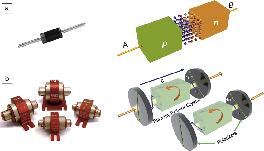
Figure 1. Comparison between a nonreciprocal electric diode and an optical isolator. (a) A typical electric diode and a sketch of the p–n junction. (b) An optical isolator and a sketch of its components, including two polarizers and a magneto-optical single crystal. The magnetization direction (B) is along the light propagation direction. The green arrows indicate the polarization direction of the polarizer. The blue arrows are the polarization state of the propagating light. The orange arrows indicate the light propagation direction.9
Unlike electrons, photons do not carry charge, making nonreciprocity far more difficult to realize in photonic materials and systems.Reference Jalas, Petrov, Eich, Freude, Fan, Yu, Baets, Popović, Melloni, Joannopoulos, Vanwolleghem, Doerr and Renner8 One kind of nonreciprocal photonic device, the optical isolator, shows similar behavior as an electric diode (Figure 1b). An optical isolator, sometimes called an “optical diode,” is a one-way traffic path for light, which allows light to pass in one direction, but not the opposite direction.9 Rather than relying on Coloumb interactions in semiconductor materials, discrete optical isolators use magneto-optical effects and magneto-optical materials, such as the ferrimagnetic oxide single-crystal material, iron garnet. When magnetized, magneto-optical materials change polarization, absorption, or the phase of light differently when they propagate forward as compared to backward propagation. Optical isolators, for instance, prevent reflected light from entering laser cavities and protect lasers from damage or frequency/intensity noise. Another nonreciprocal photonic device called an optical circulator can also be made using magneto-optical materials. This is a multiport device that mimics a traffic circle. In a three-port optical circulator, as an example, light propagation between ports follows the path 1 → 2, 2 → 3 and 3 → 1. Today, optical isolators and circulators are widely used in all kinds of optical systems for optical communications, sensing, and light detection and ranging.
However, unlike electric diodes, nonreciprocal photonic materials and devices have not been planarized and integrated on semiconductor platforms so far. With the fast development of photonic integrated circuit (PIC) technologies, nonreciprocal photonic materials and devices remain the last discrete component to be developed, which is stated as a fundamental difficulty in integrated photonics.Reference Yu and Fan10 This bottleneck problem becomes increasingly urgent with the development of on-chip laser/amplifier arrays, high-power lasers/amplifiers, and complicated integrated photonic systems.
The fundamental challenge lies squarely in the materials used. Most photonic materials and devices in a semiconductor photonic circuit are optically reciprocal. In the past decade, great efforts have been made by researchers to solve this problem. Progress has been achieved both in enabling key functionalities of nonreciprocal photonic components, and in discovering novel photonic phenomena.Reference Stadler and Mizumoto11–Reference Fan, Wang, Varghese, Shen, Niu, Xuan, Weiner and Qi15 Enabling optical nonreciprocity in PICs not only allows integration of isolators and circulators, but also enables new transport and process optical information.Reference Tsakmakidis, Shen, Schulz, Zheng, Upham, Deng, Altug, Vakakis and Boyd16,Reference Mann, Sounas and Alù17 Novel findings will continue to emerge, with the development of more and more mature nonreciprocal photonic materials and on-chip devices.
Nonreciprocal photonics: Challenges and opportunities
There are several mechanisms that have been recently explored to create photonic nonreciprocity on a chip; these have both advantages and challenges. For light propagating in a photonic material, the Lorentz reciprocity theorem is based on Maxwell’s equations and three assumptions—the material has symmetric permittivity and permeability tensors, the material is optically linear, and the material’s optical properties are time invariant. Creating a nonreciprocal photonic material lies in breaking any of these three assumptions. The endeavor for producing an on-chip nonreciprocal photonic material and device can be generally categorized into these three mechanisms, as summarized in Figure 2a–c.
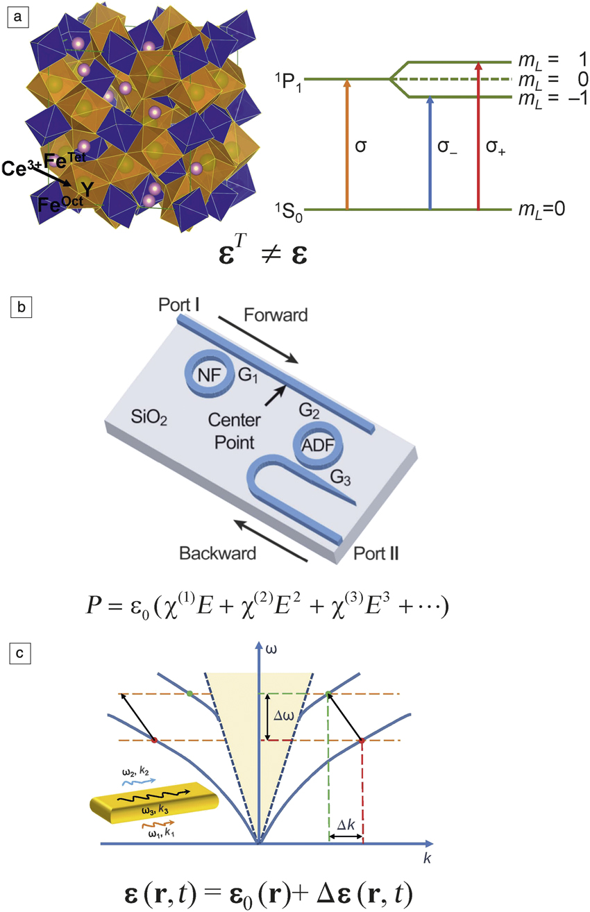
Figure 2. Three mechanisms to break optical reciprocity and corresponding materials. (a) The crystal structure of magneto-optical garnet materials. Also shown is the electric dipole transition, which shows circular birefringence and causes the Faraday rotation. The permittivity tensor of this material shows asymmetric properties (i.e., εT ≠ ε). Reprinted with permission from Reference Zvezdin and KotovReference 24. © 1997 Institute of Physics. (b) A silicon optical diode using the nonlinear Kerr effect of silicon in ring resonator structures. The equation shows the Kerr effect, where P is the polarization density, E is the incident electric field, and χ(1), χ(2), and χ(3) are the n-th order susceptibilities of the material. Reprinted with permission from Reference Fan, Wang, Varghese, Shen, Niu, Xuan, Weiner and QiReference 15. © 2012 AAAS. (c) Sketch of a spatiotemporal modulated material forming a nonreciprocal optical waveguide supporting two modes (ω1, k 1) and (ω2, k 2). The traveling wave (a microwave and acoustic wave) with frequency ω3 and wave vector k 3 causes mode conversion (by Δk and Δω) in the waveguide in the forward, but not the backward direction, as shown by the dispersion relation plot. The underlying equation shows the material’s permittivity tensor ε being modulated as a function of time, t, and location, r (i.e., spatiotemporal modulation). Reprinted with permission from Reference Sounas and AlùReference 14. © 2017 Nature Publishing Group. Note: NF, notch filter; ADF, add-drop filter.
One approach is to use materials with asymmetric permittivity or permeability tensors (i.e., the magneto-optical materials) such as garnets, as shown in Figure 2a.Reference Stadler and Mizumoto11–Reference Shoji and Mizumoto13,Reference Mann, Sounas and Alù17–Reference Shimizu and Nakano22 This approach is used for discrete nonreciprocal photonic devices, but its application to integrated devices relies on new materials, integration technologies, and mechanisms, as will be discussed later. It should be noted that it is usually the permittivity tensor, rather than the permeability tensor, which is asymmetric in magneto-optical material. The permeability tensor is reduced to a unit tensor at high frequencies in a magneto-optical materials. The fundamental mechanism of an asymmetric permittivity tensor lies in the spin–orbit coupling of magneto-optical materials, and the resulting split of electronic energy levels with different orbital angular momentum.Reference Dionne, Allen, Haddad, Ross and Lax23,Reference Zvezdin and Kotov24 The advantage of magneto-optical materials is that they are linear, passive, and naturally broadband materials. The major challenge of this approach lies in the material incompatibility (lattice, thermal mismatch, process compatibility) of magneto-optical materials with semiconductor substrates, which requires new materials and new fabrication methods for on-chip integration. The relatively weak magneto-optical effect in transparent magneto-optical materials (usually in the 10–2 to 10–3 range) also calls for novel designs to miniaturize the devices.
Another approach is to use nonlinear photonic materials, as shown in Figure 2b.Reference Fan, Wang, Varghese, Shen, Niu, Xuan, Weiner and Qi15,Reference Shi, Yu and Fan25–Reference Sounas, Soric and Alù29 This approach uses photonic materials whose optical properties, such as the index of refraction, are a function of the incident optical field intensity. Nonreciprocal light propagation can be achieved by designing an asymmetric structure using nonlinear photonic materials, such as coupled waveguides or resonators. A nonreciprocal propagation process can be realized as follows: light entering the structure from different sides couples differently to the nonlinear photonic material due to structural asymmetry, leading to different field intensity and refractive index regulation of the nonlinear photonic materials. The difference in refractive index leads to different transmission characteristics, which finally leads to nonreciprocal light propagation. An immediate advantage of this approach is that one can have a much wider material selection, because nonlinearity exists widely in common semiconductor materials such as silicon.
On the other hand, challenges reside in the nonlinear relationship between device nonreciprocity and the power of the incident light. The so-called dynamic reciprocity is also an issue, occurring when a forward strong light signal and a backward weak light signal enter the structure simultaneously. The structure is then strictly reciprocal for the weak signal, provided the weak signal is not frequency overlapped with the strong signal.Reference Shi, Yu and Fan25 Unfortunately, this is usually the application scenario for optical isolators, where a continuous-wave laser propagates along the forward direction. Nevertheless, for pulsed laser applications, this drawback may be circumvented as forward light is only turned on for a short period of time.Reference Sounas, Soric and Alù29 A different approach has also been proposed recently that uses bidirectionally pumped optical resonators and the optical Kerr effect—which describes the cubic dependence of a material’s refractive index on the amplitude of the incident electric-field amplitude (E 3)—to overcome the dynamic reciprocity problem.Reference Del Bino, Silver, Stebbings and Del’Haye30,Reference Del Bino, Silver, Woodley and Stebbings31
The third approach considers breaking the time invariance by spatiotemporal modulation of the material’s optical properties, as shown in Figure 2c.Reference Yu and Fan10,Reference Sounas and Alù14,Reference Lira, Yu, Fan and Lipson32–Reference Reiskarimian, Zhou and Krishnaswamy38 One example of this idea is to design and fabricate a photonic structure, which supports two modes with frequencies ω1 and ω2, and wave vectors of k 1 and k 2. When light propagates in the structure, a co-propagating traveling wave with frequency ω3 and wave vector k 3 is applied simultaneously to modulate the material’s index. If the phase match condition is achieved, where ω1 − ω2 = ω3 and k 1 – k 2 = k 3, these two photonic modes can convert to each other when propagating down the waveguide.Reference Sounas and Alù14 Clearly, this conversion cannot be achieved for the backward propagation with wave vectors –k 1 and –k 2 as the second equation of the phase match condition is not satisfied. Then nonreciprocal optical transmission is achieved. It should be noted that the modulation wave can be a traveling microwave,Reference Lira, Yu, Fan and Lipson32 an optomechanic acoustic wave,Reference Reiskarimian and Krishnaswamy37 or any other form that can modulate the material’s optical properties with time. The linear momentum imparted by k 3 can also be changed to an angular momentum.Reference Sounas, Caloz and Alù35,Reference Sounas and Alù36 A major advantage of the spatiotemporal approach is that one can use silicon or III–V semiconductors to achieve optical nonreciprocity. This method is also linear and independent of incident power. Also, in principle, both nonlinear nonreciprocity and this approach can operate at any wavelength by design, such as in the GHz or THz frequency regimes. Power consumption is the major challenge due to the active nature of this method.Reference Sounas and Alù14 Meanwhile, weak index modulation depth also tends to make such devices long and lossy.Reference Sounas and Alù14 Using ultralow-loss optical fibers and toroidal resonators alleviates the loss issue, but at the expense of narrow operation bandwidths.Reference Shen, Zhang, Chen, Zou, Xiao, Zou, Sun, Guo and Dong39,Reference Kang, Butsch and Russell40
In this issue
This issue includes six articles that discuss various aspects of nonreciprocal photonic materials. Du et al. provide an overview of monolithic integration of magneto-optical oxides for on-chip optical isolation.Reference Du, Fakhrul, Zhang, Hu and Ross41 They focus on pulsed laser deposition of Ce-doped Y3Fe5O12 (Ce-doped yttrium iron garnet [CeYIG]) thin films and their applications in nonreciprocal phase shift (NRPS) optical isolator devices on silicon-on-insulator (SOI) substrates. A YIG seed layer, either on the bottom or the top, promotes high-quality polycrystalline CeYIG material growth. Despite their polycrystalline nature, CeYIG thin films can show high magneto-optical figure of merit ([FOM], Faraday rotation divided by material absorption per unit length) at near-infrared communication wavelengths, which places a theoretical lower limit on device insertion loss (the additional optical loss associated with including the device in the optical circuit) of ∼1 dB, demonstrating promising potential for device applications. They also discuss process compatibility with back-end-of-line complementary metal oxide semiconductor (CMOS) processes.
Mizumoto et al. present another approach to integrated magneto-optical oxide thin films on silicon.Reference Mizumoto, Baets and Bowers42 They use wafer-bonding technology to integrate epitaxial CeYIG thin films on gadolinium gallium garnet substrates on an SOI waveguide. The bonding can be achieved by direct bonding or adhesive bonding using a transparent polymer thin film such as spin-coated divinylsiloxane-bis-benzocyclobutene. The hybrid waveguide provides a NRPS for transverse magnetic (TM) polarized modes. Mach–Zehnder-type optical isolators and circulators with isolation ratio higher than 30 dB are achieved. The temperature stability and operation bandwidth of such devices are also optimized. Finally, they present the possibility to integrate an electromagnet to provide the biasing magnetic field for these devices.
Although ferromagnetic metals such as Fe or Co are considered opaque to optical frequencies, incorporating these materials in plasmonic waveguides, where the field is localized at the interface between the ferromagnetic metal and the dielectric waveguide, may provide a higher FOM due to the unique field distribution. Shimuzu and Zayets provide a review of their study that used magnetic metal thin films for integrated optical isolator applications.Reference Shimizu and Zayets43 A 100% enhancement of the ferromagnetic metal FOM and 20× reduction of propagation loss in the optimized ferromagnetic plasmonic structure is observed. By incorporating these magnetic plasmonic waveguides on the sidewall of an InGaAsP/InP optical amplifier, they demonstrate an isolation ratio of 14.7 dB/mm due to the nonreciprocal optical loss in the forward and backward propagation directions.
The magneto-optical devices previously discussed either use the NRPS, or use the nonreciprocal loss of magneto-optical waveguides. Stadler and Hutchings describe developing a solution by building a silicon waveguide and magneto-optical thin film using the Faraday rotation.Reference Stadler and Hutchings44 The difficulty of fabricating a waveguide-based Faraday rotator is due to the structural birefringence of waveguides. In a rectangular silicon photonic waveguide, transverse electric and TM modes propagate with different phase velocities, which prevents them from converting efficiently via the magneto-optical Faraday effect. The authors solved this problem by using quasi-phase matching structures in a CeYIG or BiTIG (Bi-doped Tb3Fe5O12) thin-film cladded silicon waveguide structures. The advantage of Faraday rotators is that they can provide optical isolation for all polarizations. They also reported several key process parameters on sputter-deposited garnet thin films. TIG polycrystalline thin films on silicon are reported to show large positive Faraday rotations which are potentially useful for a “push–pull”-type Faraday rotator.
Alù and Krishnaswamy present an overview of artificial nonreciprocal photonic materials at GHz-to-THz frequencies, with a focus on spatiotemporal modulation mechanisms.Reference Alù and Krishnaswamy45 They discuss several approaches to induce spatiotemporal modulation in artificial materials, either by DC biasing active transistors or mixers, or by using mixers and delay lines to form discrete spatiotemporal modulation, or by using variators to introduce momentum bias to transmission lines/ring resonators. A more effective modulation method is to tune conductivities using transistor switches. A magnetic material-free, CMOS-compatible nonreciprocal circulator is realized at 25 GHz in a 45-nm SOI CMOS process. These devices are useful for densely integrated microwave circuits. At THz frequencies, the authors introduce a graphene-based spatiotemporal modulated metasurface, which can effectively allow nonreciprocal thermal radiation. Finally, they highlight the possibility of applying the discussed materials in electromagnetic topological insulators. Although their discussion focuses on the GHz and THz range, this approach has also been actively studied in integrated photonic devices.Reference Sounas and Alù14
The article by Chen et al. provides a perspective on using nonlinear materials for nonreciprocal photonic applications.Reference Chen, Leykam, Chong and Yang46 They used non-Hermitian photonic structures (i.e., systems defined by a Hamiltonian that is not equal to its conjugate transpose) with coupled photonic materials with loss and gain to break the structural symmetry. A coupled waveguide or resonator device structure with optical loss and gain materials forms a parity-time (PT) symmetry system, in which n(r) = n*(−r) is satisfied by design (where n(r) is the index of refraction at position r, and * indicates its complex conjugate). Breaking this symmetry either by tuning the gain, loss, or coupling strength can cause mode localization, which enhances the structural nonlinearity and ends up with nonreciprocal light propagation. Manipulating the PT symmetry phases can also cause asymmetric mode conversion. When combined with Kerr or gain saturation nonlinearity, the system can be nonreciprocal. Incorporating optical nonlinearity in topological photonic structures is another new direction for nonlinear nonreciprocal photonic materials and devices. Two structures of topological waveguide arrays and resonator lattices are discussed. Novel phenomena such as nonlinearity induced one-way topological edge states and topological soliton generation are also introduced.
Summary and future outlook
The field of nonreciprocal photonics has witnessed significant progress over the past decade. On one hand, the performance of prototype nonreciprocal materials and devices has quickly approached the application requirements. These materials and devices are at the threshold of solving the long-sought quest of realizing high performance integrated nonreciprocal photonic devices. On the other hand, a number of novel photonic phenomena have emerged in nonreciprocal photonic materials and structures, leading to unprecedented opportunities to reshape the way we transport and process optical signals today. With the fast development of nonreciprocal photonic materials and devices, we are confident of a bright future for this research field.
Acknowledgments
I would like to acknowledge Z. Wang from The Univerity of Texas at Austin for his initial assistance as a guest editor. This work is supported by the National Natural Science Foundation of China (61475031, 51522204) and the Ministry of Science and Technology of China MOST (No. 2016YFA0300802).

Lei Bi is a professor in the Department of Electronic Science and Engineering at the University of Electronic Science and Technology of China (UESTC). He received his BS degree in 2004 and MS degree in 2006, both in materials science and engineering from Tsinghua University, China. He received his PhD degree from the Massachusetts Institute of Technology in 2011. Before joining UESTC, he was an emerging memory engineer for Micron Technology Inc. from 2011 to 2013. His research interests include magneto-nanophotonics and nonreciprocal photonics. Bi can be reached by email at bilei@uestc.edu.cn.


