


I. INTRODUCTION
Nanocomposite materials are of interest for modern technological applications such as reinforced lightweight materials, catalysts, nonlinear optics, sensors, fuel cell, medical imaging, and other systems because of improved chemical, mechanical, optical, and functional properties compared to bulk materials.Reference Hu, Wei, Zhou, Ran, Li and Gao1–Reference Thimsen, Rastgar and Biswas5 The properties of nanocomposite materials depend not only on the properties of their individual component materials but also on the morphology and interfacial characteristics. Significant effort is focused on the ability to obtain control of the nanoscale structures via innovative synthetic approaches.Reference Viswanathan, Laha, Balani, Agarwal and Seal6, Reference Basak, Chen and Biswas7 Considerable research has been performed on the preparation of nanocomposite materials by multistep liquid phase synthesis,Reference Cannas, Concas, Gatteschi, Musinu, Piccaluga and Sangregorio8, Reference Bourlinos, Simopoulos, Petridis, Okumura and Hadjipanayis9 gas phase spray pyrolysis,Reference Tartaj, Gonzalez-Carreno and Serna10 and flame synthesis methods.Reference Thimsen, Rastgar and Biswas5, Reference McMillin, Biswas and Zachariah11 However, the large-scale production of nanocomposites with well-controlled size, shape, and morphology at an affordable cost still poses a challenge. Of all the methods, gas phase spray pyrolysis is most promising.Reference Viswanathan, Laha, Balani, Agarwal and Seal6
In this study, a single step gas phase method is developed to synthesize nanocomposite materials in a furnace aerosol reactor (FuAR) using premixed precursors. The advantages of this method are the ability to independently control the crystallinity, morphology, and particle size for continuous production. Magnetic iron oxide nanoparticles (usually γ-Fe2O3 and Fe3O4) are used to improve the quality of magnetic resonance imaging,Reference Hu, Wei, Zhou, Ran, Li and Gao1, Reference Ai, Flask, Weinberg, Shuai, Pagel, Farrell, Duerk and Gao12, Reference Qin, Laurent, Jo, Roch, Mikhaylova, Bhujwalla, Muller and Muhammed13 site-specific drug delivery,Reference Zhi, Qing, Gao and Ai14, Reference Pulfer, Ciccotto and Gallo15 the manipulation of cell membranes and biological heating applications.Reference Dutz, Hergt, Murbe, Topfer, Muller, Zeisberger, Andra and Bellemann16 These magnetic nanoparticles are often tailored with a surface coating (e.g., organic polymers like dextran, polyethylene glycol; metals like gold; or oxides like silica, alumina)Reference Tartaj, Gonzalez-Carreno and Serna10, Reference Gaur, Sahoo, De, Ghosh, Maitra and Ghosh17, Reference Gupta and Gupta18 to improve suspension stability and surface reactivity. Synthesis of silica-coated magnetic iron oxide nanocomposite material is demonstrated in this study as a model system for their long history in biomedical applications. A silica coating on the magnetic iron oxide core can provide better chemical, mechanical, and suspension stability and enable attachment of various bioactive ligands through surface silanol groups by covalent bonding.Reference Sun, Duan, Guo, Yun, Ma, Xu, Zhang and Gu19
First, synthesis of single component silica and magnetic iron oxide is studied to understand the decomposition mechanism of the precursors, identify the product crystallinity, and optimize the operating conditions for the controlled synthesis of nanocomposite material. Detailed results of the system necessary for design of single step synthesis of γ-Fe2O3/SiO2 nanocomposites in FuARs are not available in the literature. The single component decomposition results are further extended to synthesize silica-coated magnetic iron oxide nanocomposite material using premixed precursor. A mechanism is proposed to explain the formation of SiO2-coated γ-Fe2O3 nanocomposite in a single step in a FuAR based on chemical kinetics and verified by supporting information. The synthesized magnetic γ-Fe2O3/SiO2 nanocomposite material is further tested for suspension stability, magnetic properties, and surface reactivity (by attaching a fluorescent dye cypate-II)Reference Achilefu, Bloch, Markiewicz, Zhong, Ye, Dorshow, Chance and Liang20 to demonstrate improved properties over uncoated γ-Fe2O3 nanoparticles.
II. EXPERIMENTAL PROCEDURE
A. Solvents and reagents
Iron pentacarbonyl (IPC), 1,1,3,3-tetramethyldisiloxane (TMDS), 3-aminopropyltrimethoxysilane (APTMS), N,N′-diisopropylcarbodiimide (DIC), N,N′-dimethylformamide (DMF, Milwaukee, WI), and toluene were purchased from Sigma-Aldrich. N-hydroxybenzotriazol (HOBt) was purchased from AnaSpec (San Jose, CA). All reagents and solvents were used as received unless mentioned otherwise. Cypate-II was synthesized by literature reported methods.Reference Kohler, Fryxell and Zhang21
B. Experimental setup for nanoparticle synthesis
The experimental setup for synthesis of nanocomposite consisted of three parts. A bubbler was used as a precursor feeding system; a tubular FuAR (Lindbergh Blue M, STF54779C, effective length 106 cm and internal diameter 2.5 cm) was used to decompose the precursor; and an electrostatic precipitator (ESP) was used for particle collection (Fig. 1). A diluter system was installed after the furnace to quench the temperature of the exhaust gas coming out of reactor by mixing with particle free air. Pure IPC and pure TMDS and a premixed IPC and TMDS (1:1 v/v) in liquid phase were carried by N2 gas at 30 °C into the FuAR and were decomposed over a range of different temperatures (400–1400 °C). The temperature of the furnace was precisely controlled using a temperature controller (Lindbergh Blue M, CC58485C). Water-saturated N2 was used to provide an oxidizing atmosphere, whereas N2 was used to provide an inert atmosphere inside the reactor. Feed flow rate (1–200 ccm) and carrier gas flow (3–20 lpm) were varied to produce particles between 10–150 nm in size. The synthesized particles were collected on a cylindrical ESP with applied potential of +10 kV.

FIG. 1. Experimental setup to synthesize nanocomposite materials in a single step by furnace aerosol reactor.
C. Protocol for surface functionalization
Synthesized nanoparticles (1 mg) were dispersed in toluene (2 mL) in a glass vial by sonicating for 30 min. APTMS (100 μl) was added to the suspension and the mixture was further sonicated for 6 h at 50 °C. The nanoparticles were isolated by centrifugation and washed with toluene (3 × 1 mL), propanol (1 mL), and DMF (3 × 1 mL). The particles were then resuspended in DMF. DIC (13.9 μl, 90 μmol) was added to a solution of cypate-II (51.75 mg, 90 μmol) and HOBt (12.2 mg, 90 μmol) in DMF (1 mL) and swirled for 15 min at 600 rpm. The mixture was then transferred to the DMF suspension of nanoparticles and was swirled for 8 h at 600 rpm. The nanoparticles were isolated by centrifugation and washed with DMF (6 × 1 mL). The particles were then suspended in DMF.
D. Characterization methods
Particle size distributions were measured at the exit of FuAR using a scanning mobility particle sizer (SMPS; TSI 3936) system. The size and microstructures were verified by a transmission electron microscope (TEM; Jeol 1200EX, Peabody, MA). The crystallographic characteristics were analyzed by powder x-ray diffraction (XRD) technique (Rigaku D-MAX/A9 diffractometer, Cu Kα radiation, λ = 1.5418 Å, The Woodlands, TX), whereas elemental analysis was done on energy dispersive x-ray (EDX) analysis integrated in a scanning electron microscope (Hitachi S4500, Pleasanton, CA). The surface bonding, surface potential, magnetic property, and absorption spectrum were analyzed by Fourier transform infrared (FTIR) spectrometry (Nexus-470, Thermo Nicolet, Madison, WI), Zetasizer (Nanoseries ZS, Malvern, Westborough, MA), physical properties measurement system (PPMS 6000, Quantum Design, San Diego, CA), and UV–Visible spectrophotometer (DU640, Beckman Coulter, Fullerton, CA) respectively.
III. RESULTS AND DISCUSSION
A summary of the experimental plan along with the results are given in Table I. Single component pure silica and iron oxide nanomaterials are synthesized by decomposing pure TMDS and IPC separately to identify the product crystallinity under different reactor conditions and to optimize the operating conditions for the controlled synthesis of nanocomposite material. Amorphous silica nanoparticles are obtained when pure TMDS is oxidized between 500 and 1200 °C in a moist N2 environment (Sample 1). In presence of excess oxidizing agent, the reaction can be described by first order kinetics and the rate of oxidation (k1,Si) is assumed to be similar to the reported value for silicon tetrachloride oxidation.Reference Powers22 The oxidation rate is found to be extremely low in comparison to the nucleation rate (k2,Si)Reference Biswas, Wu, Zachariah and McMillin23 over a range of temperatures (k1,Si/k2,Si = 10−13 at 900 °C, Fig. 2), which indicates that the oxidation of the precursor is the rate limiting step for formation of silica nanoparticles.

FIG. 2. Comparison of reaction rate constant and nucleation rate constants for γ-Fe2O3 and SiO2 system.
TABLE I. Summary of experimental results along with product composition from x-ray diffraction analysis carried out at precursor flow rate 10 ccm and carrier gas flow rate 3 lpm.

FuAR, furnace aerosol reactor; IPC, iron pentacarbonyl; TMDS, 1,1,3,3-tetramethyldisiloxane.
Pure IPC has a decomposition temperature of 250 °C, where CO is removed stepwise from the central Fe atom.Reference Karlsson, Deppert, Wacaser, Karlsson and Malm24 Being extremely reactive, the Fe atoms can be readily oxidized to produce iron oxides. In this study, moisture is utilized as a mild oxidizing agent during the synthesis process. The moisture can further act as stabilizing agent for the metastable γ-Fe2O3 phase.Reference Rane, Verenkar, Pednekar and Sawant25 Amorphous iron oxide is obtained up to 400 °C (Sample 2), and a mixture of amorphous and γ-Fe2O3 is obtained up to 600 °C (Sample 3) when IPC is decomposed in a moist (saturated with water vapor) N2 atmosphere. Metastable γ-Fe2O3 is the final product of IPC decomposition between 800 and 1000 °C in both N2 and moist N2 atmosphere (Samples 4–8) as identified by XRD (Fig. 3). Because of the thermodynamic stability of α-Fe2O3, it is obtained as the major product above 1200 °C (Samples 9 and 10) for all reaction conditions. Further, α-Fe2O3 is the final product between 900 and 1400 °C when air is used as the oxidizing agent. The oxidation reaction is led via a multistep structurally similar intermediate, like cubic Fe, FeO, and Fe3O4.Reference Rane, Verenkar, Pednekar and Sawant25 The metastable γ-Fe2O3 state is stabilized by the combined effect of short residence time (3–15 s), high thermal quenching rate after the furnace reactor, and use of mild oxidizing agent (moisture). The reported value of oxidation rate (k1,Fe) is compared with the nucleation rate (k2,Fe) for IPCReference Biswas, Wu, Zachariah and McMillin23 over a wide range of temperature (k1,Fe/k2,Fe = 4.9 × 10⁻⁶ at 900 °C), and it is concluded that oxidation is the rate limiting step for iron oxide nanoparticle formation.

FIG. 3. X-ray diffraction pattern of uncoated and silica-coated γ-Fe2O3 samples synthesized at different experimental conditions in Table I (H, hematite; M, maghemite).
The single component decomposition results are extended to synthesize nanocomposite oxides by cofeeding two precursors. The processes for the decomposition of the premixed precursors are the same as of single component decomposition viz. oxidation, nucleation, and coagulation as discussed earlier. However, the final composition and morphology of the mixed oxide may be chemically identical or chemically distinct based on the relative decomposition kinetics of the precursors. To build a generalized mechanism for the formation of different morphologies starting with premixed precursors, the two precursors are symbolized as P1 and P2 and the oxides formed by these precursors are symbolized as AxOy and BpOq, respectively. Formation of chemically identical core-shell type AxOy/BpOq nanocomposite is proposed for a binary system of premixed precursors having high relative decomposition rate (i.e., kA » kB or kA « kB, where kA and kB are the rate of formation of oxide AxOy and BpOq respectively). In case of kA » kB, the core of the nanocomposite is made of AxOy, whereas the shell of the nanocomposite is formed by BpOq, as graphically represented in Path-I of Fig. 4. Because of the higher rates of oxidation of precursor P1, AxOy particles are produced before BpOq. Once formed, the AxOy vapor nucleates rapidly followed by growth of particle size by collisions and sintering. The growth of AxOy is followed by formation of BpOq by chemical decomposition. The BpOq may nucleate heterogeneously on the surface of existing AxOy nanoparticles. Finally, at the downstream regions of the furnace, the nanocomposite gets sintered to form uniform core-shell type morphology. In a similar way, chemically identical BpOq coated with AxOy can be synthesized with proper choice of precursors (where kA « kB) as shown in Path-III of Fig. 4. A chemically distinct mixed morphology is proposed for the decomposition of premixed precursors with similar decomposition rate constant (i.e., kA ≈ kB) as graphically represented in Path-II of Fig. 4. Because of similar relative decomposition kinetics, both AxOy and BpOq are formed simultaneously, followed by formation of a mixed oxide nanomaterial.

FIG. 4. Generalized formation mechanism of AxOy/BpOq type nanocomposites based on reaction kinetics starting with premixed precursors P1 and P2. In this study, P1 and P2 represent IPC and TMDS, whereas AxOy and BpOq represent Fe2O3 and SiO2, respectively. The value of k1,Fe/k1,Si (4.0 × 10⁸ at 900 °C) satisfies the Path-I in the proposed generalized formation mechanism. Combined analysis of Fe2O3/SiO2 nanocomposite by transmission electron microscopic (TEM) image, Fourier transform infrared (FTIR) spectra, and zeta potential supports the proposed mechanism.
To meet the objective of controlled synthesis of a silica-coated iron oxide nanocomposite, the rate of iron oxide formation should be higher than the rate of silica formation based on the Path-I of the proposed mechanism. In this study, both the precursors, IPC and TMDS are selected by the relative decomposition kinetics (k1,Fe/k1,Si = 4.0 × 10⁸ at 900 °C) for preferential production of a silica-coated iron oxide nanocomposite. When the premixed precursor (TMDS and IPC) is fed into the FuAR, initially, IPC is oxidized at a faster rate compared to TMDS (k1,Fe » k1,Si) forming only iron oxide. The iron oxide vapor is homogeneously nucleated (as k1,Fe « k2,Fe at 900 °C) and the particles grow by collision and sintering to form larger aggregates. This is followed by formation of silica molecules that are then heterogeneously nucleated on the existing iron oxide aggregates to form a shell. Downstream of the furnace, the silica deposited on the surface of iron oxide aggregate is sintered to form a spherical core-shell type nanocomposite system. In this study, the residence time inside the reactor is maintained in such a way to ensure complete decomposition of IPC to iron oxide for all the cases (Figs. S1–S3 in supplementary information; supplemental files can be viewed online by visiting http://journals.cambridge.org/jmr.). However, oxidation of TMDS based on the kinetic data of silicon tetrachloride is found to be partial for some reaction conditions at high flow rates (Figs. S2 and S3; supplemental files can be viewed online by visiting http://journals.cambridge.org/jmr.).
A spherical SiO2-coated γ-Fe2O3 nanocomposite is synthesized in moist N2 atmosphere between 900 and 1200 °C (Samples 11 and 13), which supports the proposed mechanism. The nanocomposite material obtained by this process has similar crystallinity to that individual single component system. However, a SiO2-coated Fe nanocomposite (Samples 12 and 14) is obtained in pure N2 environment, unlike γ-Fe2O3 nanoparticles obtained from single component pure IPC decomposition under similar conditions (Samples 5 and 8). This observation is consistent with the proposed mechanism that pure Fe nanoparticles are formed as a reaction intermediate during the decomposition of IPC. The Fe nanoparticles being highly reactive get converted to γ-Fe2O3 by reaction with air in the diluter (Fig. 1) before being collected in the ESP. The conversion of Fe to γ-Fe2O3 during single component IPC decomposition can be avoided by using inert gas in the diluter and ESP system during collection. In case of two premixed precursors, the conversion of Fe to γ-Fe2O3 is hindered by formation of the shell SiO2 layer on the surface of the Fe nanoparticles. The synthesis of stable Fe/SiO2 nanocomposite clearly supports the formation of core shell type morphology with silica on the surface of the surface of highly reactive nanosized Fe core. The proposed mechanism can also be used to explain the synthesis of nanocomposite materials in flame aerosol reactors.Reference McMillin, Biswas and Zachariah11
The single step synthesis of nanocomposite material proposed in this study is highly effective to control the morphology, crystallinity, and size of the nanostructure. Proper choices of precursors with relative decomposition rates are essential to determine the morphology, whereas control of the decomposition temperature and the reaction environment are the key factors that control the crystallinity of the product as demonstrated earlier. Mean size of nanocomposite can be varied independently without altering the morphology and crystalline composition of the nanocomposite by varying the feed flow rate and the carrier gas flow rate. A decrease in feed flow rate decreases the mean particle size, whereas a decrease in carrier gas flow rate increases the residence time and particles grow to larger sizes. TEM images of collected nanocomposites (Sample 11) clearly show the formation of spherical γ-Fe2O3/SiO2 nanocomposite with core-shell morphology with some pure silica particles by nucleation [Fig. 5(a)]. The difference in surface bonding of uncoated and SiO2-coated γ-Fe2O3 particles as observed by FTIR analysis also supports the formation of core shell morphology [Fig. 5(b)] with silica forming the shell of the nanocomposite. Two absorption bands around 570 and 470 cm−1, characteristic of disordered γ-Fe2O3,Reference Tartaj, Gonzalez-Carreno and Serna10 are observed on uncoated γ-Fe2O3 particles (Samples 5 and 6). These two peaks disappear for the synthesized core-shell type γ-Fe2O3/SiO2 (Sample 11) and Fe/SiO2 (Sample 12) nanocomposite. Appearance of two bands at 1180 and 1080 cm−1 characteristic of the Si-O-Si asymmetric stretching vibration modes and a peak at 798 cm−1 corresponding to the Si-O-Si symmetric stretching vibration modesReference Tartaj, Gonzalez-Carreno and Serna10 indicate the presence of silica on the surface. Another broad band at 960 cm−1 confirms the presence of surface active Si-OH groupsReference Tartaj, Gonzalez-Carreno and Serna10, Reference Bruni, Cariati, Casu, Lai, Musinu, Piccaluga and Solinas26 required for surface modification. The composite nanoparticles have only signature of peaks associated with silica, with very weak signal of iron oxide. This also supports that silica is on the surface of the composite nanoparticles. Synthesis of particles in size ranges from 10 to 150 nm has been demonstrated by varying the precursor feed flow rate (1–200 ccm) and carrier gas flow rate (3–20 lpm). The mean particle size measured with the SMPS (Fig. 6) at different inlet conditions is in close agreement with the particle size observed on the TEM images.

FIG. 5. (a) TEM image of synthesized core-shell type γ-Fe2O3/SiO2 nanocomposite (Sample 11). The inset is elemental analysis of the same sample using energy dispersive x-ray spectroscopy. (b) FTIR spectra of synthesized uncoated and silica-coated γ-Fe2O3 samples at different experimental conditions.

FIG. 6. Scanning mobility particle sizer measured size distribution of γ-Fe2O3/SiO2 at different feed flow rates.
A zeta potential measurement is used to compare the stability of the synthesized nanoparticles in the aqueous system at pH 5.3 [Fig. 7(a)]. In aqueous suspension, γ-Fe2O3 particles get partially ionized to produce hydronium ions (H3O+). The H3O+ get adsorbed on the surface of the particles to generate small positive surface charge.Reference Kunzelmann, Jacobasch and Reinhard27 This is confirmed by the measured +17 mV zeta potential value of pure γ-Fe2O3 (Sample 6). The zeta potential value for the silica-coated γ-Fe2O3 nanocomposite (Sample 11) is −34 mV, which is close to the zeta potential value of pure silica particles (Sample 1) measured in this study (−55 mV) and also reported in literature.Reference Kim and Lawler28 The high surface charge on the silica coated γ-Fe2O3 nanocomposites indicates better stability of these particles over uncoated γ-Fe2O3 nanoparticles in an aqueous suspension. Furthermore, zeta potential values of γ-Fe2O3/SiO2 nanocomposite close to that of pristine silica nanoparticles supports the full coverage of the iron oxide particles by silica.

FIG. 7. (a) Zeta potential analysis of uncoated and silica-coated γ-Fe2O3 nanoparticles. (b) Hysteresis loop analysis of synthesized uncoated and silica-coated γ-Fe2O3 samples at different experimental conditions.
A high saturation magnetization (Ms) and small remanent magnetization are desired for biomedical applications. A high saturation magnetization would require a small external magnetic field to transport the particles, whereas a superparamagnetic behavior with low remanent magnetization would make these particles less susceptible to agglomeration after removal of the external magnetic field. The measured value of saturation magnetization for synthesized γ-Fe2O3/SiO2 nanocomposite (Sample 11) is 19 emu·g−1 at 300 K [Fig. 7(b)] and is close to the reported value for γ-Fe2O3/SiO2 nanocomposite (20–40 emu·g−1) synthesized by a wet chemical method.Reference Cannas, Casula, Concas, Corrias, Gatteschi, Falqui, Musinu, Sangregorio and Spano29 A lower saturation magnetization value for γ-Fe2O3/SiO2 nanocomposite compared to pure γ-Fe2O3 (74 emu·g−1)Reference Cannas, Concas, Gatteschi, Falqui, Musinu, Piccaluga, Sangregorio and Spano30 is caused by the presence of diamagnetic silica coating on the surface of γ-Fe2O3, and it agrees with calculated values based on mass of nanocomposite. The magnetic moment of the nanocomposite can be controlled by varying thickness of the silica coating that is readily produced by changing the feed ratio of precursors at the inlet to the FuAR. The superparamagnetic behavior of the synthesized product is confirmed by the absence of hysteresis in the magnetization (M) versus applied magnetic field (H) plot at 300 K. However, at 4 K, the particles exhibit ferromagnetic features including coercivity (Hc) and remanent magnetization (MR). The synthesized core-shell type Fe/SiO2 nanocomposite (Sample 12) might be a promising alternative to the γ-Fe2O3/SiO2 system for higher magnetic moment (35 emu·g−1 at 300 K with no hysteresis) because of to higher saturated magnetization of the Fe core (156 emu·g−1).Reference Suslick, Fang and Hyeon31
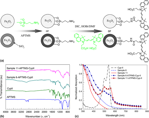
To demonstrate the surface reactivity, pure and silica-coated γ-Fe2O3 nanoparticles are functionalized with a carbocyanine dye cypate-II loaded via an amide bond on APTMS. Cypate is selected for its known in vivo optical imaging applications in the near-infrared region.Reference Achilefu, Dorshow, Bugaj and Rajagopalan32 The schematic of the surface functionalization is given in Fig. 8(a). In the case of uncoated γ-Fe2O3 nanoparticles, APTMS attaches to the surface hydroxyl group formed by partial ionization; whereas for silica-coated γ-Fe2O3 nanoparticles, APTMS reacts with the surface silanol group via covalent bonding. Attachment of APTMS and cypate-II on the nanoparticle surface is confirmed by FTIR measurements [Fig. 8(b)]. Pure APTMS has peaks in the 2800–3000 cm−1 characteristic of amine group, whereas cypate-II has several peaks in the 1300–1700 cm−1 characteristic of C=O and C-O bond. The nanoparticles functionalized with cypate-II loaded via the APTMS link show fingerprint of both cypate-II and APTMS. The presence of cypate-II is further supported by the UV–Visible spectra of the dye-modified nanoparticles in water [Fig. 8(c)]. The pristine iron oxide and silica-coated iron oxide can absorb only below the 500 nm region, whereas the dye-modified pristine and silica-coated iron oxide has a distinct absorption band between 530–630 nm that is characteristic of the cypate-II. Further, the dye-modified γ-Fe2O3/SiO2 nanocomposite has better absorption intensity compared to uncoated γ-Fe2O3 nanoparticles, which indicate better functionalization ability of γ-Fe2O3/SiO2 nanocomposite.

FIG. 8. (a) Schematic diagram of surface functionalization of pure and SiO2-coated γ-Fe2O3 nanoparticles using cypate-II via 3-aminopropyltrimethoxysilane (APTMS) linkage. (b) FTIR analysis of APTMS, cypate-II, and cypate-II functionalized pure and silica-coated iron oxide nanoparticles. (c) UV–Visible analysis of uncoated (Sample 6), silica-coated γ-Fe2O3 (Sample 11) and surface modified nanoparticles functionalized with cypate-II suspended in water.
IV. CONCLUSIONS
In summary, controlled synthesis of a core-shell type γ-Fe2O3/SiO2 nanocomposite is demonstrated in a single step in a FuAR using premixed precursors. A generalized mechanism for the formation of pristine and chemically distinct nanocomposite is proposed based on relative reaction kinetics. Synthesis of silica-coated γ-Fe2O3 nanocomposite depends on choice of proper precursors as proposed in the generalized mechanism. Combined analysis of XRD, TEM, FTIR, and zeta potential results are presented to support the formation of spherical, core-shell type γ-Fe2O3/SiO2 nanocomposite. The presence of surface silanol groups is indicated by FTIR analysis, and γ-Fe2O3/SiO2 nanocomposite shows better surface reactivity than pure γ-Fe2O3 does, when functionalized with a fluorescent dye (cypate-II). The newly designed dye-modified magnetic nanocomposite system with multitasking ability may be used clinically as imaging agent. The proposed generalized method can be used for preparation of other nanocomposite systems with choice of proper precursors.
ACKNOWLEDGMENTS
We thank the Department of Defense (DoD-MURI FA9550-04-1-0430) and the Center of Materials Innovation at Washington University in St. Louis for partial support for this work. Partial funding by the McDonnell Academy Global Energy and Environmental Partnership (mageep.wustl.edu) and the Indo-US Science and Technology Forum is gratefully acknowledged.


