


Impact Statement
Encapsulation consists in enclosing a substance inside a membrane in order to protect it and control the exchanges with the environment. Recent innovative applications use capsules containing active principles, fragrances, flavours, phase change materials or organ cells. A microfluidic methodology is presented to measure the membrane elastic properties of microcapsules with a liquid core. The method is based on an inverse analysis of the deformed profiles of capsules flowing in a capillary tube. A fluid–structure numerical model that accounts for nonlinear large deformations of the capsule wall, corresponding to a strain-hardening or -softening material behaviour, provides the database for the inverse analysis. The method is applied to artificial microcapsules with a cross-linked ovalbumin membrane and is validated by comparison with measures in a microrheological device. The advantage of the microfluidic method is that it is simple to implement and can be automatized for on-line measurements.
1. Introduction
Encapsulation consists of enclosing some internal substance inside a membrane in order to control the exchanges between the environment and the internal medium. The capsule contents are thus prevented from dispersing or degrading and can eventually be released where and when needed. Capsules are found in nature in the form of cells, bacteria, seeds and eggs. For example, a red blood cell (RBC) is a natural capsule that transports haemoglobin, allows oxygen and carbon dioxide exchanges through the membrane, but withstands the hydrodynamic stresses prevalent in blood circulation. In industry, applications of small-scale encapsulation have become ubiquitous. Classical examples are found in cosmetics or food industry for fragrance or flavour protection (Reference Gibbs, Kermasha, Alli and MulliganGibbs, Kermasha, Alli, & Mulligan, 1999; Reference Miyazawa, Yajima, Kaneda and YanakiMiyazawa, Yajima, Kaneda, & Yanaki, 2000; Reference Zuidam and NedovicZuidam & Nedovic, 2010) but also in energy storage with phase change materials encapsulated in microcarriers (Reference Zhao and ZhangZhao & Zhang, 2011). In medicine, new treatment techniques are being developed, such as liposome encapsulation of fragile mRNA for vaccine applications (Reference Kowalski, Rudra, Miao and AndersonKowalski, Rudra, Miao, & Anderson, 2019) or the development of new-generation bioartificial organs where xenogeneic cells (e.g. pancreas cells for diabetic patients) are encapsulated to prevent rejection reactions (Reference Espona-Noguera, Ciriza, Canibano-Hernandez, Orive, Hernandez, de Burgo and PedrazEspona-Noguera et al., 2019). Microencapsulation thus offers a tremendous potential in the process engineering world, but many scientific challenges remain to be tackled, especially on the engineering and physical aspects.
Encapsulated objects exist with a wide range of size (from nanometric to millimetric), shape and mechanical property (from solid to highly deformable particles). In this paper, we will focus on prototypical initially spherical capsules, i.e. liquid droplets enclosed by a thin elastic membrane, which are widely used in industry. We exclude solid beads, as well as vesicles, which are enclosed by a lipid bi-layer with fluid membrane properties. In most applications, capsules are suspended in a carrying fluid. When the suspension is flowing, the particles are subjected to large deformations under the hydrodynamic stresses, which may lead to the membrane buckling and wrinkling and even to breakup. The motion of a microcapsule in a flowing fluid thus constitutes a formidable problem of fluid–structure interactions in the domain where the fluid stresses are mostly due to viscous and pressure effects and where the structure is undergoing large deformation. A crucial issue is thus the constitutive behaviour of the wall material. Specifically, a neo-Hookean (NH) constitutive law is typically used to model walls with a strain-softening behaviour, as exhibited by polymer membranes with rubber-like elasticity. For membranes with a network of strong covalent bonds, the strain-hardening behaviour is often modelled by a Skalak (SK) law, which was initially designed to represent the mechanical behaviour of the bi-layer membrane of the RBC (Reference Skalak, Tozeren, Zarda and ChienSkalak, Tozeren, Zarda, & Chien, 1973). However, for artificial capsules, the generalized Hooke's law (GH), which corresponds to the thin membrane limit of a homogeneous three-dimensional law, constitutes an interesting alternative to the SK law. Indeed, the GH law assumes a linear relation between the stress and the deformation in the reference undeformed configuration, but exhibits a nonlinear strain-hardening behaviour under large deformation. Furthermore, it can account for variable degrees of wall area distensibility.
Experimentally, the measurement of the wall mechanical properties is difficult because capsules are small and fragile. For biological cells such as RBCs with a very deformable lipid bi-layer membrane, micropipette aspiration (Reference Heinrich and RawiczHeinrich & Rawicz, 2005) or optical tweezers (Reference Avsievich, Zhu, Popov, Bykov and MeglinskiAvsievich, Zhu, Popov, Bykov, & Meglinski, 2020) have been proposed. Those methods are not adapted to measure artificial microcapsules with a size ranging from a few tens of micrometres to a millimetre, because the deforming forces that are applied are a few pN. If this force level is sufficient to substantially deform cells, it is much too low to have any measurable effect on capsules. Correspondingly, different techniques to test capsules have been proposed over the years, such as compression between two parallel plates for millimetre-size particles (Reference Carin, Barthès-Biesel, Edwards-Lévy, Postel and AndreiCarin, Barthès-Biesel, Edwards-Lévy, Postel, & Andrei, 2003; Reference Risso and CarinRisso & Carin, 2004), atomic force indentation (Reference de Loubens, Deschamps, Georgelin, Charrier, Edward-Lévy and Leonettide Loubens et al., 2014; Reference Fery and WeinkamerFery & Weinkamer, 2007), deformation in a simple shear flow created in a counter-rotating Couette viscometer (Reference Chang and OlbrichtChang & Olbricht, 1993b; Reference Koleva and RehageKoleva & Rehage, 2012; Reference Rehage, Husmann and WalterRehage, Husmann, & Walter, 2002; Reference Walter, Rehage and LeonhardWalter, Rehage, & Leonhard, 2000) or in a planar hyperbolic flow (Reference Barthès-BieselBarthès-Biesel, 1991; Reference Chang and OlbrichtChang & Olbricht, 1993a; Reference de Loubens, Deschamps, Georgelin, Charrier, Edward-Lévy and Leonettide Loubens et al., 2014). Those techniques are powerful, but require a sophisticated (and often expensive) set-up. Another drawback is that they are all off line and are difficult to automatize.
Another method consists of flowing individual capsules in a microchannel (with circular or square cross-section) and measuring their velocity and deformed profiles by means of video microscopy. Depending on the flow conditions, an initially spherical capsule can take a parachute or slug shape when its diameter is of the same order as the channel cross-dimension. The velocity and deformed profile of each capsule are then compared with the corresponding quantities computed by a full numerical model of the capsule in flow: this inverse analysis yields a value of the shear elastic modulus of the enclosing wall (Reference Chu, Salsac, Leclerc, Barthès-Biesel, Wurtz and Edwards-LévyChu et al., 2011; Reference Gubspun, Gires, De Loubens, Barthès-Biesel, Deschamps, Georgelin and SalsacGubspun et al., 2016; Reference Hu, Sévénié, Salsac, Leclerc and Barthès-BieselHu, Sévénié, Salsac, Leclerc, & Barthès-Biesel, 2013; Reference Lefebvre, Leclerc, Barthès-Biesel, Walter and Edwards-LévyLefebvre, Leclerc, Barthès-Biesel, Walter, & Edwards-Lévy, 2008). The advantage of the technique is that it is straightforward, can be automated (Reference Quesada, Dupont, Villon and SalsacQuesada, Dupont, Villon, & Salsac, 2020) and may thus yield statistical results for a population. However, up to now, the modulus values thus obtained have mostly been used in a relative sense to analyse the effect of a specific parameter (membrane polymerization conditions, capsules size) on the mechanical properties of a given capsule population. The modulus values have never been compared with those measured with another independent experiment (e.g. capsule in shear flow).
It is the aim of this paper to provide a robust methodology for the assessment of the mechanical properties of a microcapsule wall, based on an inverse analysis of microchannel flow measurements. In particular, we will make a full numerical study of the motion and deformation of initially spherical capsules with a GH wall when they flow in a cylindrical tube. This will allow us to evaluate the importance of the resistance to area dilation. In order to facilitate the inverse analysis, the results will be gathered in plots of the main deformation and motion parameters as functions of the confinement and flow strength. As an illustration, the methodology will be applied to evaluate the wall shear elastic modulus of artificial microcapsules with a reticulated ovalbumin membrane. We will show that changing the assumptions made regarding the wall constitutive behaviour leads to different evolution of the shear modulus with the deformation level: this allows us to assess the type of rheological behaviour of the capsule wall, i.e. strain hardening or softening. A further novelty of this study is the validation of the microchannel results by means of a comparison with those obtained from microrheometric measurements on the same capsules in a counter-rotating Couette device.
In § 2, we outline the fluid–structure interactions problem and its numerical solution. In § 3, we provide new results on the tube flow of a capsule with a GH membrane, such as deformed profiles and plots of the relevant parameters as functions of confinement, flow strength and wall Poisson ratio. We also compare the results with those obtained with different wall constitutive laws (SK and NH). In § 4, we describe the fabrication of the microcapsules, how they are tested in microfluidics and microrheometry devices and how mechanical properties are identified from captured images of their deformed shape at steady state in both cases. We then apply the two methods to a capsule population and discuss their ability to predict the membrane elastic behaviour. Section 5 is dedicated to concluding remarks.
2. Deformation of a spherical capsule in flow: model
We consider an initially spherical capsule (radius  $a$) which is filled with an internal liquid (density $\rho$, viscosity $\mu$) and enclosed by a thin hyperelastic isotropic membrane (surface shear modulus $G_s$, area dilation modulus $K_s$). This capsule is freely suspended in another incompressible Newtonian liquid (density $\rho$, viscosity $\mu$), subjected to flow. Details of the analysis can be found in the review paper of Reference Barthès-BieselBarthès-Biesel (Reference Barthès-Biesel2016) and the references therein.
2.1. Membrane mechanics
As the viscous forces exerted by the fluid lead to large shape distortions of the particle, care must be taken in the modelling of the wall mechanics. Correspondingly, the position of the membrane material points is denoted  $\boldsymbol{X}$ in the undeformed reference state and $\boldsymbol x(\boldsymbol X,\,t)$ in the deformed configuration at time $t$. The local deformation of the membrane surface is measured by the Green–Lagrange strain tensor $\boldsymbol e = \frac {1}{2}(\boldsymbol {F}^T \boldsymbol{\cdot} \boldsymbol{F} - \boldsymbol {I})$, where $\boldsymbol F = \partial {\boldsymbol x} / \partial {\boldsymbol X}$ is the gradient of the transformation and $\boldsymbol I$ the identity tensor. Two invariants of $\boldsymbol e$ can be defined as
 \begin{equation} I_1 = \textrm{tr} (\boldsymbol{F}^T \boldsymbol{\cdot} \boldsymbol{F}) - 2 = \lambda_1^2 + \lambda_2^2 - 2,\quad I_2 = \textrm{det}(\boldsymbol{F}^T \boldsymbol{\cdot} \boldsymbol{F}) - 1 = \lambda_1^2 \lambda_2^2 - 1, \end{equation}
where  $\lambda _1$ and $\lambda _2$ represent the in-plane principal extension ratios. Invariant $I_1$ measures the shear deformation, whereas $I_2$ measures the local surface dilation. Since the membrane is infinitely thin, the three-dimensional stresses in the membrane are replaced by Cauchy tensions (forces per unit arclength of deformed surface). The Cauchy tension tensor $\boldsymbol {\sigma }$ depends on a strain energy function $w_s(I_1,\,I_2)$ per unit undeformed surface area
 \begin{equation} \boldsymbol \sigma = \frac{1}{\lambda_1\lambda_2} \boldsymbol F \boldsymbol{\cdot} \frac{\partial w_s}{\partial \boldsymbol e} \boldsymbol{\cdot} \boldsymbol F^T. \end{equation}
 Several constitutive laws with constant material coefficients have been proposed to govern the energy–deformation relationships. They are usually derived from classical three-dimensional laws in the limit where the initial thickness  $h$ of the capsule wall tends to zero. The surface shear modulus is then related to the usual three-dimensional shear modulus $G$ by
 \begin{equation} G_s = h G. \end{equation}
The simplest law, for isotropic and hyperelastic materials, is the GH law, in which  $w_s$ is a quadratic function of $\boldsymbol e$
 \begin{equation} w_s^{GH} = G_s \left( \textrm{tr} (\boldsymbol e^2) + \frac{\nu_s}{1-\nu_s} [\textrm{tr}(\boldsymbol e )]^2 \right) = \frac{G_s}{4} \left( 2I_1 - 2I_2 + \frac{1}{1-\nu_s} I_1^2 \right), \end{equation}
where  $\textrm {tr}(\boldsymbol e )$ denotes the trace of $\boldsymbol e$ and $-1<\nu _s <1$ is a surface Poisson ratio. The area dilation modulus is then $K_s = G_s (1+\nu _s)/(1-\nu _s)$, which implies that $\nu _s \rightarrow 1$ corresponds to an area incompressible membrane. Note that $\boldsymbol \sigma$ is a linear function of $\boldsymbol e$ for small deformation ( $\boldsymbol F \simeq \boldsymbol I$), but becomes a nonlinear function of $\boldsymbol e$ for large deformation, with a strain-hardening type behaviour.
The two-dimensional form of the NH law, classically used to describe volume-incompressible rubber-like materials, is given by
 \begin{equation} w_s^{\textit{NH}} = \frac{G_s}{2} \left( I_1 - 1 + \frac{1}{I_2 + 1} \right). \end{equation}
Because of the hypothesis of volume incompressibility, area dilation is balanced by membrane thinning so that  $K_s=3G_s$. Under large deformation, the Cauchy tensions exhibit a strain-softening type behaviour.
In order to describe anisotropic biological bi-layers (such as the RBC membrane), Reference Skalak, Tozeren, Zarda and ChienSkalak et al. (Reference Skalak, Tozeren, Zarda and Chien1973) proposed a purely two-dimensional law (SK) with independent surface shear and area dilation modulus
 \begin{equation} w_s^{\textit{SK}} = \frac{G_s}{4} \left[ (I_1^2 + 2I_1 - 2I_2) + CI_2^2 \right].\end{equation}
The area dilation modulus is  $K_s = (1+2C)G_s$, in which the dimensionless parameter $C$ regulates the resistance to area dilation. Under large deformation, the Cauchy tensions exhibit a strain-hardening type behaviour, that becomes more pronounced as $C$ increases.
For  $C=1$ and $\nu _s=0.5$, corresponding to $K_s=3G_s$, the three NH, GH, SK laws have the same small-deformation behaviour, but predict different material responses for large strains (Reference Barthès-Biesel, Diaz and DheninBarthès-Biesel, Diaz, & Dhenin, 2002; Reference Lac, Barthès-Biesel, Pelekasis and TsamopoulosLac, Barthès-Biesel, Pelekasis, & Tsamopoulos, 2004).
When the inertia of the capsule membrane is neglected, the local equilibrium equation of the membrane reads
 \begin{equation} \nabla_s \boldsymbol{\cdot} \boldsymbol{\sigma} + \boldsymbol q = 0, \end{equation}
where  $\nabla _s$ is the surface gradient and $\boldsymbol q$ is the load, i.e. the external force per unit area of deformed capsule surface $C_t$ at time $t$. A no-slip condition is also imposed at the capsule wall
 \begin{equation} \boldsymbol v(\boldsymbol x,t) = \partial \boldsymbol x(\boldsymbol X,t)/\partial t \quad \boldsymbol x \in C_t, \end{equation}
where  $\boldsymbol v(\boldsymbol x,\,t)$ is the velocity of the internal and external fluids on the capsule deformed surface.
2.2. Fluid–structure coupling and numerical method
The flows of the internal and external liquids are governed by the Stokes equations, subjected to no-slip conditions on the capsule wall and on the flow domain outer boundary  $B$. The velocity of the capsule wall is given by an integral equation (Reference PozrikidisPozrikidis, 2005)
 \begin{equation} \boldsymbol{v}({\boldsymbol{x}}) = {\boldsymbol{v}}^{\infty}({\boldsymbol{x}}) - \frac{1}{8\pi \mu} \left[ \int_{C_t} {\boldsymbol{J}}\boldsymbol{\cdot} \boldsymbol{q} \,\textrm{d} S(\boldsymbol{y}) + \int_{B} {\boldsymbol{J}} \boldsymbol{\cdot} \boldsymbol{f}^{ + }\,\textrm{d} S(\boldsymbol{y}) \right],\quad \boldsymbol{x} \in C_t,\end{equation}
where  $\boldsymbol {v}^{\infty }(\boldsymbol {x})$ is the unperturbed flow velocity in the absence of a capsule. The force $\boldsymbol q$ on the membrane is determined from the mechanics of the capsule wall (equation (2.7)). The additional friction force on the domain boundaries $\boldsymbol { f}^{+}$ must be computed as part of the solution (Reference Hu, Salsac and Barthès-BieselHu, Salsac, & Barthès-Biesel, 2012). The Green's function $\boldsymbol {J}$ is defined as
 \begin{equation} \boldsymbol{J} = \frac{1}{||\boldsymbol x -\boldsymbol y||}\boldsymbol I + \frac{(\boldsymbol x -\boldsymbol y) \otimes (\boldsymbol x -\boldsymbol y)}{||\boldsymbol x -\boldsymbol y||^3}. \end{equation}
The problem is governed by the following non-dimensional parameters:
• The size ratio $a/l$, where $l$ is the flow characteristic length.
• The membrane capillary number
$Ca_s = {\mu V}/{G_s}$, where $V$ is the flow characteristic velocity.• The ratio between dilation and shear modulus
$K_s/G_s$.


We solve this fluid–structure problem by coupling the boundary integral method (BIM) to calculate the flow field, to the finite element method (FEM) to calculate the force exerted by the membrane on the fluid (Reference Hu, Salsac and Barthès-BieselHu et al., 2012; Reference Walter, Salsac, Barthès-Biesel and Le TallecWalter, Salsac, Barthès-Biesel, & Le Tallec, 2010). Triangular  $P_1$ elements are used to discretize all the boundaries. There are 5120 $P_1$ elements and 2562 nodes on the capsule membrane, corresponding to a characteristic element size $\Delta h_c/l=0.07$. At each time step, the boundary integral equation (2.9) is solved to yield the velocity of the membrane. A second-order Runge–Kutta method is then used to integrate equation (2.8) and obtain the new deformed position of the membrane material points. This information is sent to the FEM solid solver to compute the load $\boldsymbol q$, which is then sent to the fluid solver to repeat the process. The explicit nature of the time integration implies very small time steps for the scheme to be stable. Here, we use a time step $\Delta tV/l=5\times 10^{-4}$, which guarantees stability. All the reported results pertain to a steady state, for which the surface area of the capsule varies by less than $10^{-3}\times (4 \pi a^2)$ over a non-dimensional time $tV/l=1$. The precision of the numerical scheme has been shown to be $O(\Delta h_c/l)^2$ when $P_1$ elements are used (Reference Dupont, Salsac, Barthès-Biesel, Vidrascu and Le TallecDupont, Salsac, Barthès-Biesel, Vidrascu, & Le Tallec, 2015; Reference Walter, Salsac, Barthès-Biesel and Le TallecWalter et al., 2010).
3. Numerical prediction of the capsule deformed shape
3.1. Deformation of a capsule flowing in a cylindrical tube
We first consider the case where a closely fitting capsule is subjected to a bounded Poiseuille flow with mean velocity  $V$, created in a straight channel with a circular cross-section of radius $l$ (figure 1a). We seek the steady motion and deformation of a centred capsule. Since there is a liquid film around the capsule (figure 1b), its velocity $v_c$ is different from $V$ and must be computed as part of the solution. Presently, results are available for capsules with a NH or SK membrane flowing in circular (Reference Hu, Salsac and Barthès-BieselHu et al., 2012; Reference Lefebvre and Barthès-BieselLefebvre & Barthès-Biesel, 2007; Reference PozrikidisPozrikidis, 2005) or square section tubes (Reference Hu, Sévénié, Salsac, Leclerc and Barthès-BieselHu et al., 2013; Reference Kuriakose and DimitrakopoulosKuriakose & Dimitrakopoulos, 2011). In this section, we provide new results for capsules with a GH membrane law.

Figure 1. Schematic illustration of an initially spherical capsule (contour  $C_0$) subjected to Poiseuille flow in a cylindrical channel with radius $l$ (a). Typical lengths characterizing the capsule deformation (contour $C_t$ at time $t$):
$t$):  $L_z,\, L_p$ in the channel (b) and $L_1,\,L_2$ in an unbounded simple shear flow (c).
The capsule centre  $O$ is initially located on the channel axis, in the middle of the tube (total length $20\,l$) and is moved back there at each time step. The flow domain boundary $B$ consists of the channel wall and of the entrance $S_{in}$ and exit $S_{out}$ sections. On the channel wall, no-slip conditions are enforced. The entrance and exit sections are far enough from the capsule for undisturbed Poiseuille flow conditions to prevail
 \begin{equation} \boldsymbol{v}^{\infty} = 2V[1-(x^2 + y^2)/l^2]\boldsymbol{e}_z. \end{equation}
The coupled BIM–FEM solver is used, where the characteristic dimension of the channel boundary elements is  $\Delta h_w/l=0.14$, except in a central part with length $2\,l$, where a refined mesh is used with $\Delta h_w/l=0.07$. For $a/l \geq 0.9$, we pre-deform the capsule into an ellipsoid that can fit inside the channel and we then follow the same procedure, while accounting for the induced pre-deformation stresses.
For a specific membrane law, the problem solution yields the capsule deformed profile and velocity  $v_c/V$ for given values of $a/l$ and $Ca_s$. The overall capsule deformation is quantified with two parameters: the total length $L_z/l$ and the parachute depth $L_p/l$ that are easy to measure experimentally (figure 1b).
3.1.1. Capsule with a GH membrane
The combined effects of  $Ca_s$ and of $\nu _s$ on the deformed profiles of the capsule are shown in figure 2. The results are similar to those reported previously for other membrane laws. The capsule length $L_z$ increases with flow strength. A parachute always forms for confinement ratios up to 0.9, with depth $L_p$ increasing with $Ca_s$. For higher confinements $a/l >0.9$, the parachute forms only when the flow strength exceeds a critical value $Ca_{sc}$, which increases with $a/l$: specifically $Ca_{sc}$ increases from 0.03 to 0.06 when $a/l$ increases from 1 to 1.1.

Figure 2. Tube flow: effect of flow strength and surface Poisson ratio  $\nu _s$ on the steady-state capsule profile in the $yz$-plane. (a) $Ca_s=\textit{0.01}$; (b) $Ca_s=\textit{0.07}$; (c) $Ca_s=\textit{0.15}$.
The new results in figure 2 pertain to the effect of the membrane dilation modulus as measured by  $\nu _s$. We first note that $\nu _s$ has no effect on the front profile of the capsule for given values of $a/l$ and $Ca_s$. The same remark applies to the global capsule profile for small flow strength (e.g. $Ca_s=0.01$) and thus moderate deformation (figure 2a). Any influence of $\nu _s$ occurs at the rear of the capsule: the main effect of a reduced resistance to dilation is an increase of the parachute depth (figure 2b,c), resulting in a sharp parachute edge at high flow strength (figure 2c). When such a sharp edge appears, the capsule is near the transition to continuous elongation, where it cannot reach a steady shape.
The plots in figure 3a,b give the evolution of the two lengths  $L_z$ and $L_p$ (characterizing the capsule deformation) with the confinement ratio $a/l$ and capillary number $Ca_s$. Note that the capsule velocity $v_c$ is larger than the average flow velocity $V$, due to the film around the capsule (figure 3c). The ratio $v_c/V$ decreases from 2 for zero size capsules (that would travel with the maximum fluid velocity) to almost unity for very large capsules (that would travel with almost the average fluid velocity).

Figure 3. Tube flow: plots of the (a) capsule total length  $L_z$, (b) parachute depth $L_p$ and (c) centre of mass velocity $v_c$ as a function of $Ca_s$ and $\nu _s$. Same colour/line style code as in figure 2; the symbols refer to different size ratios as shown in (b).
3.1.2. Effect of constitutive laws on capsule deformation
The effect of the membrane constitutive laws on capsule deformation for  $K_s=3G_s$ is shown in figure 4 for different confinement ratios and flow strengths. For low flow strength ( $Ca_s=0.07$) and low size ratio (e.g. $a/l=0.8$), the capsule deformation is small and the three laws almost predict the same profile, as expected. As we increase $a/l$, while keeping $Ca_s=0.07$, the stresses in the capsule membrane increase: as a consequence, a capsule with a strain-softening NH membrane deforms more than capsules with strain-hardening SK or GH membranes (figure 4a). Eventually, the large ( $a/l=1.1$) NH capsule does not reach steady state and undergoes continuous elongation (like the capsules with a GH law and $\nu _s<0.5$). As the flow strength increases (figure 4b), continuous elongation of NH capsule occurs for lower confinement ratios, specifically for $a/l\ge 0.85$ when $Ca_s=0.15$ (Reference Hu, Sévénié, Salsac, Leclerc and Barthès-BieselHu et al., 2013). By contrast, capsules with a strain-hardening membrane can always reach a steady state. The difference between the SK or GH membranes is very small, and occurs at the rear of the capsule for large confinement ratios, only. The plots of the characteristic lengths and velocity ratio as functions of $a/l$ and $Ca_s$ are shown in figure 5 for strain-softening and strain-hardening membranes (where SK results have been eliminated, as they were very close to the GH ones). All the points in figure 5 correspond to steady situations.

Figure 4. Tube flow: effect of the membrane constitutive law on the capsule deformed profile for  $K_s=\textit{3}G_s$. (a) $Ca_s=\textit{0.07}$; (b) $Ca_s=\textit{0.15}$.

Figure 5. Tube flow: plots of the (a) capsule total length  $L_z$, (b) parachute depth $L_p$ and (c) centre of mass velocity $v_c$ as a function of $Ca_s$ for two membrane laws with $K_s=\textit{3}G_s$. Blue dotted line, NH; black full line, GH ( $\nu _s=\textit{0.5}$); the symbols refer to different size ratios as shown in (b).
The plots in figures 3 and 5 can be used to perform the inverse analysis of the experimental profiles: from the measured values of the lengths  $L_z$ and $L_p$, we can deduce the size ratio $a/l$ and capillary number $Ca_s$ for a given membrane law. In practice it is easy to measure $v_c$, but difficult to control $V$: the plots giving $v_c/V$ as a function of $a/l$ and $Ca_s$ are thus essential for the final determination of the membrane shear elastic modulus $G_s=(\mu v_c/Ca_s)({V}/{v_c})$, where $\mu$ is the suspending fluid viscosity, which is supposedly known. From the experimental point of view, the plots in figures 3 and 5 indicate clearly that the inverse analysis can be performed with precision only if the capsule deformation is significant enough for a parachute to form, i.e. for values of $Ca_s>0.05$. Depending on their size and composition, microcapsules can have a shear modulus that varies between $\sim$0.05 and 1 N m $^{-1}$ (Reference Gubspun, Gires, De Loubens, Barthès-Biesel, Deschamps, Georgelin and SalsacGubspun et al., 2016). They can be observed without too much blurriness only if their velocity is no more than a few mm s $^{-1}$. This means that the fluid viscosity must be large (of order 1 Pa s) and that a high pressure is thus necessary to flow the suspension in a small diameter capillary tube. Typical experiments with the corresponding inverse analysis are described in § 4.2.
3.2. Deformation of a capsule in a simple shear flow
The deformation of a spherical capsule in a simple shear flow is well documented (see the review by Reference Barthès-BieselBarthès-Biesel (Reference Barthès-Biesel2016) and the references therein). The influence of different membrane laws (NH, SK) has been studied, except for the case where the capsule wall is governed by a GH law with different values of the surface Poisson ratio. It is thus one aim of this paper to fill this void and provide a full database for this situation. We now consider the case where the capsule is freely suspended in an unbounded simple shear flow with undisturbed velocity given by
 \begin{equation} \boldsymbol{v}^{\infty} = \dot{\gamma} y \boldsymbol{e}_z,\end{equation}
where  $\dot {\gamma }$ is the shear rate. The flow problem is governed by equation (2.9), where the boundary $B$ is taken far enough from the capsule centre for the perturbation $\boldsymbol f^+$ to be negligible. As a consequence, only the first integral remains in equation (2.9). The only problem parameters are then the capillary number, now defined as $Ca_s= \mu \dot {\gamma } a/G_s$, and the ratio $K_s/G_s$. For a given membrane law, the model provides the deformed profile of the capsule as a function of $Ca_s$. As the deformed capsule is approximately ellipsoidal, we determine its ellipsoid of inertia which has semi-principal axes $L_1,\, L_2$ in the shear plane (figure 1c) and $L_3$ in the vorticity direction. The deformation in the shear plane is then quantified by the Taylor parameter $D_{12}=|L_1-L_2|/(L_1+L_2)$. Results for $D_{12}$ are available in the case $K_s/G_s=3$ for NH, SK and GH membranes (Reference Dupont, Salsac, Barthès-Biesel, Vidrascu and Le TallecDupont et al., 2015; Reference Lac and Barthès-BieselLac & Barthès-Biesel, 2005; Reference Walter, Salsac, Barthès-Biesel and Le TallecWalter et al., 2010), and $L_3$ is never given, although it is necessary to determine the deformed capsule volume. New results for GH and NH membranes are thus presented in figure 6, where the relation between $D_{12}$ and $Ca_s$ is given as well as the evolution of $L_3$ with $D_{12}$. For a GH membrane, the effect of decreasing $\nu _s$, i.e. the dilation modulus, is to increase the deformation for the same flow strength. For $\nu _s=0$, the capsule undergoes continuous elongation and eventually ruptures for $Ca_s\gtrsim 0.4$. The same phenomenon appears around $Ca_s=1$ and $D_{12}\simeq 0.6$, for a NH membrane.

Figure 6. Simple shear flow: plots of the (a) capsule deformation in the shear plane and (b) profile semi-axis  $L_3$ along the vorticity direction for NH and GH laws.
The plots of figure 6 are simple to use: for a given membrane law, the value of deformation  $D_{12}$ yields the value of $L_3$ and $Ca_s$. Knowing $L_3,\, L_1$ and $L_2$, it is easy to compute the volume of the capsule and its initial radius $a$. The elastic modulus $G_s$ is obtained from $Ca_s$, knowing the values of $\dot {\gamma }$ and $\mu$, both given by the shear apparatus.
4. Experimental observation of capsule deformation and identification of the wall mechanical properties
4.1. Capsule fabrication
Microcapsules are fabricated by means of interfacial polymerization with cross-linking reactions (Reference Edwards-Lévy, Andry and LévyEdwards-Lévy, Andry, & Lévy, 1993). Specifically, 1 ml of an aqueous solution, consisting of 10 % (w/v) ovalbumin (Sigma) dissolved in phosphate buffer (pH 7.4, Sigma), is dispersed in 10 ml of vegetable oil (ISIO 4, Lesieur) at a stirring speed of 2400 r.p.m. in a laboratory vortex (Heidolph Top-Mix 94323) for 10 s. Then, 10 ml of vegetable oil containing 2.5 % (w/v) terephthaloyl chloride (Sigma) is added to the emulsion. Interfacial reticulation is allowed to develop at rest for 15 min. The suspension is then centrifugated at 800 r.p.m. for 1 min. The supernatant is removed and replaced by vegetable oil containing 2 % (v/v) Tween 20 (Sigma). The pellet is manually resuspended in this mixture by gentle successive aspirations and ejections from a pipette tip. After this first washing step, the suspension is centrifugated at 800 r.p.m. for 1 min. The supernatant is then removed and replaced by a 2 % (v/v) solution of Tween 20 diluted in distilled water. The same resuspension procedure as in oil–Tween 20 mixture is used. This second washing step is followed by three rinsing stages, each one consisting of gently suspending the capsules in distilled water, centrifugating the suspension and resuspending the pellet in clean distilled water. This procedure yields quasi-spherical deformable capsules with radii ranging from a few tens up to a few hundreds of microns. The suspension is filtered through a 100  ${\rm \mu}$m sieve in order to narrow the size range. The capsules are resuspended in glycerol for deformation experiment purposes. We have verified that there is no shape alteration and no apparent fluid exchanges across the membrane for at least 3 h, which is the maximum duration of an experiment, after which the capsules are discarded.
4.2. Identification of wall elasticity by flowing microcapsules in a microfluidic cylindrical capillary
The microfluidic flow system, shown in figure 7a, consists of a straight 28 mm long cylindrical capillary tube with an internal diameter  $2l=75\ {\rm \mu}$m (Capillary tube 1), embedded in another tube (Capillary tube 2), which is immersed in polydimethylsiloxane (Sylgard 184, Dow Corning) to eliminate optical distortions (Reference Lefebvre, Leclerc, Barthès-Biesel, Walter and Edwards-LévyLefebvre et al., 2008). Just prior to an experiment, 500 ${\rm \mu}$l of filtered capsule pellet is suspended in 12 ml glycerol (Sigma). The capsule suspension, which has a viscosity of $\mu =0.92\ \hbox{Pa}\ \hbox{s}$ at 20 $^{\circ }$C, is injected into the microchannel by means of a pressure controller (EZ-Flow, Fluigent). Pressure values range from 800 to 1500 mbar, which provide capsule velocities from 0.8 to 6 mm s $^{-1}$. Image acquisitions of individual capsules flowing in the tube are performed with a fast camera (Fastcam MINI AX50, Photron) at frequencies $f$ ranging from 2000 to 6000 Hz and an exposition time $1/f$. The camera is mounted on a DMI8 microscope (Leica) with a $\times$ 40 magnification and 0.6 numerical aperture objective.

Figure 7. (a) Microfluidic set-up; (b) microrheometry set-up. All lengths are in  $\mu m$; PDMS, polydimethylsiloxane.
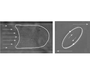
Recordings are performed at least 5 mm downstream of the inlet to ensure that the capsule has reached its steady state. The capsule contours are manually extracted from the experimental images using ImageJ (NIH, USA). The capsule mid-surface and channel wall are assumed to be located in the middle of the corresponding dark contour lines (figure 8), leading to an error of  $\pm$1 pixel on the extracted contour points and to an error of order $\pm$2 % on the extracted lengths $L_z^\textit{exp}$ and $L_p^\textit{exp}$. The capsule velocity $v_c^\textit{exp}$ is determined by manually measuring the displacement of the capsule front between the first and last of 10 successive images and dividing it by the corresponding time duration. The error on $v_c^\textit{exp}$ is also of order $\pm$2 %.

Figure 8. (a,d) Experimental image of the capsule in a cylindrical tube (diameter  $\textit{75}\ \mu m$) with extracted contour (full line); (b,e) two potential fits of the extracted profiles using a NH law; (c,f) profile fits with different membrane laws. The parameters of the different fits are gathered in table 1.
The inverse analysis strategy consists of identifying the mechanical properties from the experimental deformed profiles using the data-driven automatic procedure of Reference Quesada, Dupont, Villon and SalsacQuesada et al. (Reference Quesada, Dupont, Villon and Salsac2020). The databases contain the predicted steady-state values of  $L_z$ and $L_p$ as functions of parameters $Ca_s$ and $a/l$ for the different constitutive laws (NH, GH $\nu _s = 0.5,\, 0.2,\, 0$) corresponding to figures 3 and 5. For a given constitutive law, we project the experimental values $L_z^\textit{exp}$ and $L_p^\textit{exp}$ onto the ( $L_z$, $L_z-L_p$) hypersurface that contains all the admissible solutions. The corresponding $Ca_s$ and $a/l$ values are identified by means of diffuse approximation. This approximation uses a local weighted least squares fitting that is valid in a small neighbourhood around the point ( $L_z^\textit{exp}$, $L_z^\textit{exp} - L_p^\textit{exp}$) and containing 14 neighbours of the database. Knowing the length–parameter relationship for the 14 data points, we deduce the values of $Ca_s^{\textit{fit}}$ and $(a/l)^{\textit{fit}}$ for the measured lengths by solving an inverse problem. The surface representing $v_c/V$ as a function of $a/l$ and $Ca_s$ is decomposed into triangles with vertices on the database points. The point $\{Ca_s^{\textit{fit}},\,(a/l)^{\textit{fit}}\}$ corresponds to one triangle of the velocity surface and the ratio $(v_c/V)^{\textit{fit}}$ is the distance weighted average of the values of $v_c/V$ on the three vertices (Delaunay triangulation procedure). The membrane shear modulus $G_s$ is then
 \begin{equation} G_s = \frac{\mu v_c^\textit{exp}}{Ca_s^{\textit{fit}}}\left(\frac{V}{v_c}\right)^{\textit{fit}}. \end{equation}
As a check, we compute the numerical deformed profile of the capsule, corresponding to the values  $\{Ca_s^{\textit{fit}},\,(a/l)^{\textit{fit}}\}$ and compare it with the experimental profile. The modified (i.e. mean) Hausdorff distance $H/a$ between the two profiles gives an estimate of the precision of the inverse analysis. Any capsule that cannot be fitted with $H/a \leq 0.06$ is discarded. We also discard non-symmetrical profiles which cannot be analysed with the model.
For a given law, different fits are obtained using the values  $L_z^\textit{exp},\, L_p^\textit{exp}$ (Fit 1), decreasing/increasing $L_z^\textit{exp}$ (and thus $L_p^\textit{exp}$) by 2 % (Fit 2/Fit 3, respectively) and finally, decreasing/increasing $L_p^\textit{exp}$ by 2 % while keeping $L_z^\textit{exp}$ constant (Fit 4/Fit 5, respectively). This procedure allows us to evaluate the sensitivity of the inverse analysis to experimental error. It also allows us to compute a mean value and deviation for $G_s$. As an example, we consider two deformed profiles (figure 8a,d) and the resulting inverse analysis fits with a NH law (figure 8b,e showing only Fits 2 and 3 for clarity). The corresponding fit values are gathered in table 1. For the smaller capsule ( $a/l\simeq 0.9$), the five fits are equally good in terms of Hausdorff distance, but lead to a 27 % dispersion of shear modulus values ( $G_s=0.048\,\pm\,0.0013\ {\rm N}\,{\rm m}^{-1}$): this dispersion is mostly due to the fact that, for capsules smaller than the tube radius ( $a/l \le 0.9$), the lengths $L_z$ or $L_p$ do not vary much with $Ca_s$ (figure 5) thus a small variation of $L_z$ leads to a large variation of $Ca_s$. For the larger capsule ( $a/l\simeq 1$), the Hausdorff distance is near the acceptable limit of $0.06 a$ (except for Fit 4 which is discarded), mainly, because the tips are not fitted very well. However, the capsule being large, the dispersion is only 13 % on the shear modulus values ( $G_s=0.039\,\pm 0.0005$ N m $^{-1}$). This shows that an absolute value of the precision of the inverse analysis procedure cannot be evaluated with a single parameter such as $H/a$ as it depends on the quality of the fit and also on the capsule size and deformation level. The same procedure can be applied to fit the profile with other membrane laws as shown in figure 8c,f where only the results of Fit 2 are shown. Of course, the values of $G_s$ depend on the law as shown in table 1.
Table 1. Size ratio  $a/l$, surface capillary number $Ca_s$, surface shear modulus $G_s$ and non-dimensional modified Hausdorff distance $H/a$ corresponding to the different profile fits of figure 8. The NH and GH ( $\nu _s=\textit{0.2},\ \textit{0.5}$) results correspond to Fit 1

4.3. Identification of wall elasticity using microrheometry
We now use a microrheometric device to determine the capsule membrane properties by subjecting the particles to a simple shear flow. A 10 ml volume of a capsule suspension in glycerol (volume concentration 0.5 %) is placed in a counter-rotating Couette viscometer (MCR 702, Anton Paar). The viscometer consists of a transparent cup and an opaque inner cylinder with a 1 mm gap (figure 7b). A  $45^{\circ }$ mirror, located under the cup, allows us to observe the capsules in the shear plane by means of a camera (model LM165M, Lumenera) with a $\times\,5$ magnification and 0.14 numerical aperture objective, operating at 32 frames s $^{-1}$. The camera is focused on the mid-plane of the gap, where the flow velocity is zero. We only record the capsules that are stationary and appear clearly in the observation window (which is easier to say than to do). During an experiment, the shear rate $\dot {\gamma }$ is kept constant for a typical duration of 10 min and is progressively increased. The contour of the deformed capsules is extracted manually with ImageJ. A least squares fit of the contour with an ellipse yields the values of the semi-axes $L_1$ and $L_2$ (figure 9). Note that the pictures are not as sharp as those obtained with the microfluidic set-up, due to inferior performance of the camera included in the device and to the fact that it is challenging to keep the capsule steady. The fuzziness of the profile leads to an error of $\pm$20 % on $D_{12}$. Correspondingly, it is unreasonable to try to analyse capsules with $D_{12}<0.35$.

Figure 9. Experimental image of the capsule in a simple shear flow with extracted contour. The scale indicates  $\textit{75}\ \mu m$.
The inverse analysis is straightforward, because the deformation of the capsule depends on only one parameter,  $Ca_s$. For a given law and shear rate $\dot {\gamma }$, the measured semi-axes $L_1$ and $L_2$ yield the deformation $D_{12}$ from which we deduce $Ca_s$ and $L_3/a$ using the plots in figure 6. The capsule radius is thus $a=\sqrt {L_1L_2 L_3/a}$ and the shear modulus is $G_s= \mu \dot {\gamma } a/Ca_s$. The capsule presented in figure 9 is subjected to a 350 s $^{-1}$ shear rate in a fluid with viscosity 0.756 Pa s. The radius is $a=45\ {\rm \mu}$m and the deformation $D_{12}=0.38$ provides a value of shear elastic modulus equal to $G_s=0.044$ N m $^{-1}$ for a NH membrane and to 0.024 or 0.038 N m $^{-1}$ for a GH membrane with $\nu _s=0.5$ or 0.2, respectively.
4.4. Characterization of a capsule population
As we measure a capsule suspension in both set-ups, we can have results on a population. In order to compare the values of  $G_s$ obtained with different membrane laws, it is convenient to use the mean profile elongation $\Lambda =p/2\pi a$ where $p$ is the perimeter of the capsule deformed profile in the $yz$-plane. The nonlinear constitutive law, which is appropriate to model the capsule membrane, is the one that yields the same constant value of $G_s$ for any deformation level $\Lambda$. Note that all laws should lead to the same small deformation value of $G_s$, since they are then equivalent.
The results from the microfluidic device are shown in figure 10, where the values of  $G_s$, obtained from the analysis of different deformed capsules with an estimated radius in the range 32–47 ${\rm \mu}$m, are plotted as a function of $\Lambda$ for three different membrane laws (NH and GH with $\nu _s=0.5$ or 0.2). The error bars correspond to the dispersion of the five fits. As explained earlier, they are larger for small deformation and/or small Ca s. In order to visualize the trend of the data, a best fit of $G_s$ values obtained with each law, is also shown.

Figure 10. Plots of surface shear modulus  $G_s$ as a function of capsule mean deformation $\varLambda$. Symbols represent the constitutive law. The lines show a linear best fit for the corresponding points. The shaded areas correspond to the mean value $G_s\pm \textit{25}\,\%$ obtained with microrheometry.
The values of  $G_s$ obtained with NH law are approximately constant with a mean value $G_s=0.043\pm 0.004$ N m $^{-1}$. This indicates that the NH law is a good candidate to model the ovalbumin membrane of the capsules. The results obtained with GH ( $\nu _s=0.5$) law are in the same range as the results for NH law for small deformation ( $\Lambda =1.06$), as expected. However, the values of $G_s$ tend to decrease with increasing deformation: this means that the strain-hardening GH law is not fit to model the membrane behaviour under large deformation, since the parameter $G_s$ must be decreased as deformation increases. The larger dispersion of the NH values of $G_s$ compared with that of the GH ones is linked to the fact that the values of $Ca_s$ are larger for the GH analysis than for the NH one.
Furthermore, it is possible to verify if, indeed, the capsule membrane is shear-softening. This is done by increasing the flow strength until a continuous elongation regime is reached. The set-up described in figure 7a did not allow for high enough flow velocity to reach this regime. However, as a proof of concept, we have flowed the same capsules in a slightly different microfluidic system consisting of a square section ( $100\times 100\ {\rm \mu}$m $^2$) channel. Continuous elongation of a capsule is then observed under high flow velocity, as shown in figure 11.

Figure 11. (a--c): successive profiles of a capsule showing continuous elongation in a square section channel ( $\textit{100}\times \textit{100}\ \mu$ $m^{\textit{2}}$, $a=\textit{50}\ \mu$m, $V_c\sim \textit{23}$ mm s $^{-\textit{1}}$, $\mu=\textit{0.92}$ Pa s). The capsule has travelled approximately $\textit{200}\ \mu m$ between two successive profiles and is clearly undergoing break-up in the last picture. Images taken by E. Hasiak.
When we use the GH law with  $\nu _s=0.2$, it it difficult to fit the experimental profiles with the same values of $a/l$ as those used for the NH or GH ( $\nu _s=0.5$) fits: the size ratio has to be increased by 10 % to 15 %. This leads to values $Ca_s$ that are smaller than those obtained with the other fits and consequently to larger values of $G_s$, as can be noted in figure 10. The significant decrease of $G_s$ with deformation and the dispersion of the fit results using the GH ( $\nu _s=0.2$) law indicate that $\nu _s=0.2$ is not appropriate to model capsules with an ovalbumin membrane. Reference Gubspun, de Loubens, Trozzo, Deschamps, Georgelin, Edwards-Lévy and LeonettiGubspun et al. (Reference Gubspun, de Loubens, Trozzo, Deschamps, Georgelin, Edwards-Lévy and Leonetti2017) conducted pore flow experiments on capsules with a reticulated human serum albumin membrane (thus very similar to the present capsules with an ovalbumin membrane) and provide deformed profiles with their respective size ratios $a/l$ and $Ca_s$ values obtained assuming a GH membrane with $\nu _s=0.4$. We have tried to fit the published profiles with the same law and with the indicated parameter values without success. This may indicate that the GH law with values of $\nu _s<0.5$ is not very appropriate to model this type of capsule.
When we analyse the microrheometric measurements, it is not possible to give a trend of the values of  $G_s$ with $\Lambda$ because of the fairly large error on $D_{12}$. We have measured 25 capsules with a radius between 30 and 46 ${\rm \mu}$m subjected to deformation levels $0.35\,{<}\,D_{12}\,{<}\,0.5$. There is a definite effect of the membrane constitutive law because the deformation is fairly large. Correspondingly, the mean value of the shear modulus depends on the law: it is found to be $G_s\ {=}\ 0.039\pm 0.01$ N m $^{-1}$ for NH law, $G_s=0.021\pm 0.007$ N m $^{-1}$ for GH ( $\nu _s=0.5$) and $G_s=0.033\pm 0.01$ N m $^{-1}$ for GH ( $\nu _s=0.2$), all with a standard deviation of $\pm$25 %. This large deviation is mostly linked to the error in the measurement of $D_{12}$. Another source of error is also due to the fact that the inverse analysis uses deformation curves obtained for a viscosity ratio equal to unity between the internal and external liquids, whereas this ratio is much smaller than 1 in the experiments. However, Reference Foessel, Walter, Salsac and Barthès-BieselFoessel, Walter, Salsac and Barthès-Biesel (Reference Foessel, Walter, Salsac and Barthès-Biesel2011) showed that the influence of this viscosity ratio is very small and does not modify significantly the relationship between $D_{12}$ and $Ca_s$, up to $D_{12} \simeq 0.5$. This is why we have discarded results with deformation larger than 0.5.
Altogether, the microrheometric  $G_s$ values, shown as shaded areas in figure 10, overlap well with the results obtained with the microfluidic tube for large deformation. This is clear for the NH law, for which $G_s$ is found to have the nearly constant value $0.043\pm 0.004$ N m $^{-1}$ by microfluidics or $0.039\pm 0.01$ N m $^{-1}$ by microrheometry. In the case of GH ( $\nu _s=0.5$) law, this conclusion applies for the range of values of $G_s$ obtained for large deformation ( $\Lambda >1.10$) i.e. $0.027\sim 0.015$ N m $^{-1}$ by microfluidics and $0.021\pm 0.007$ N m $^{-1}$ by microrheometry.
This validates the microfluidic approach to measure microcapsule properties.
5. Conclusion
The main objective of this paper was to propose a microfluidic methodology to measure the elastic properties of a population of microcapsules. Why this method? Because the operating principle is simple and the experimental set-up fairly inexpensive, apart from the visualization devices (microscope and high-speed camera), which are indispensable to any dynamic micro-apparatus. The method is based on the observation of flowing capsules in a cylindrical capillary tube and an inverse analysis of the deformed profiles. The latter requires a full numerical model of the fluid–structure interaction, that accounts for nonlinear membrane elastic properties, which we provide under the form of databases for an initially spherical capsule with a membrane governed by a NH or general Hooke's law with different surface Poisson ratios. We also detail how the inverse analysis can be automated to provide information on the type of elastic constitutive law that governs the capsule wall material together with the value of the corresponding elastic parameters. This is possible because the confinement imposed by the microfluidic configuration allows for large deformation of the capsule membrane. Note that a microfluidic method, based on a similar inverse analysis adapted to the specific case of RBCs, has been proposed to analyse automatically large cell populations (Reference Saadat, Huyke, Oyarzun, Escobar, Vreeide, Shaqfeh and SantiagoSaadat et al., 2020). The shape characterization is different from the one presented here, as it had to be adapted to smaller, discoidal particles.
Another microrheological method is used where the capsules are subjected to a simple shear flow in a counter-rotating Couette device. The method consists in capturing the deformed profile of those capsules with their centre of mass in the zero velocity plane, which is somewhat tricky to perform. The necessary databases for the inverse analysis are also provided for an initially spherical capsule with a membrane governed by a NH or general Hooke's law with different surface Poisson ratios.
We validate the two methods by confronting the results obtained with either one on a population of artificial capsules with cross-linked ovalbumin membrane. We test three types of membrane laws, to find for which constant values of  $G_s$ are obtained: a strain-softening NH law and two strain-hardening GH laws with dilation to shear ratios $K_s/G_s=3$ or 1.5 ( $\nu _s=0.5$ or 0.2). The microfluidic method predicts that the membrane shear modulus $G_s$ is approximately constant for a NH law: this indicates that this constitutive law is appropriate to model the mechanical behaviour of the ovalbumin membrane. In contrast, the values of $G_s$ decrease with deformation for GH ( $\nu _s=0.5$) law and exhibit much dispersion for GH ( $\nu _s=0.2$) law. With the microrheometric method, there is too much experimental uncertainty to decide which law is best adapted to describe the constitutive behaviour of the membrane material. On average though, the high-deformation values of the membrane shear elastic modulus are the same with the two methods for any given law: this validates the microfluidic methodology. A further potentiality of the microfluidic methodology is that once $G_s$ is known, it is possible in principle to check if the capsule membrane is strain-softening (NH law) or strain-hardening (GH law). This can be done by increasing the flow rate to exceed the critical value of $Ca_s$ past which continuous elongation occurs when the membrane is strain-softening. If continuous elongation is observed, the NH law is a good candidate to model the wall behaviour. If not, the wall is then strain hardening and the GH law should serve as a good approximation.
The feasibility study on artificial ovalbumin capsules allows us to define the optimal conditions to diminish the impact of inherent uncertainties. For the microfluidic method to be precise, the capsule global deformation should be large enough, i.e. the elongation ratio  $\Lambda$ of the perimeter of the observed profiles should be larger than 1.05. Furthermore, the size ratio between the capsule and the tube radii, should not be smaller than 0.9: indeed, for smaller ratios, the deformation does not vary much with flow strength, thus leading to large errors in the determination of the latter. Note that the capsule must be transparent enough to allow measurement of the penetration length of the parachute, which is an essential feature of the deformation. Consequently, the microfluidic method will not work on opaque capsules, whereas the rheometric method would still be pertinent.
Potentially, the great strength of this technique is that it allows us to determine the type of membrane constitutive behaviour: strain hardening or softening. This is very important as, under given flow stress, strain-softening capsules may be more prone to deformation induced damage than strain-hardening ones. Furthermore, the microfluidic method is well adapted for quality control, as it allows small batches of a capsule suspension to be diverted from a production line to a measuring test section. Of course, images and their contours should be acquired automatically, as done by Reference Minetti, Podgorski, Coupier and DuboisMinetti, Podgorski, Coupier and Dubois (Reference Minetti, Podgorski, Coupier and Dubois2014) or Reference Saadat, Huyke, Oyarzun, Escobar, Vreeide, Shaqfeh and SantiagoSaadat et al. (Reference Saadat, Huyke, Oyarzun, Escobar, Vreeide, Shaqfeh and Santiago2020), and post-treated automatically as explained in this paper.
Funding Statement
We gratefully acknowledge funding from the China Scholarship Council (PhD scholarship of X.Y. Wang) and from the European Research Council (ERC) under the European Union's Horizon 2020 research and innovation programme (grant agreement no. ERC-2017-COG – MultiphysMicroCaps).
Declaration of Interests
The authors report no conflict of interest.
Author Contributions
A.V.S. and D.B.B. created the research plan, designed experiments and numerics and formulated the analytical/numerical problem. X.Y.W. and C.D. led the numerical simulations and implemented the inverse analysis. A.M. performed all the experiments. All the authors contributed on the analysis of the results.
Data Availability Statement
Raw data are available from the corresponding author (A.V.S.).
Ethical Standards
The research meets all ethical guidelines, including adherence to the legal requirements of the study country.


 Open access