


Introduction
The continuous improvement of aero engines and land-based gas turbines leads to increasing gas inlet temperatures and the demands for new materials. Such increased temperatures are possible with thermal barrier coating (TBC) systems consisting of Al- and Cr-containing bond coatings for enhanced oxidation- and corrosion resistance and ceramic TBCs, which are essential for thermal isolation [Reference Clarke and Phillpot1]. The difference in thermal expansion coefficients between the metal substrate and the TBC would lead to delamination. A metallic bond coat can improve the bonding between substrate and TBC and can reduce the risk of spallation of the ceramic top coat. Therefore, MCrAlY overlay coatings are applied to superalloy components, tailored to provide protection against high-temperature oxidation and hot corrosion [Reference Goward2, Reference Nicholls3, Reference Hejrani, Sebold, Nowak, Mauer, Naumenko, Vaßen and Quadakkers4, Reference Gil, Shemet, Vassen, Subanovic, Toscano, Naumenko, Singheiser and Quadakkers5, Reference Naumenko, Pillai, Chyrkin and Quadakkers6, Reference Webler, Ziener, Neumeier, Terberger, Vaßen and Göken7]. Studies have investigated hardness, Young’s modulus, diffusion or the influence of bond coats with different chemical compositions on the mechanical properties of the superalloys so far [Reference Hebsur and Miner8, Reference Funk, Ma, Eberl, Schönung, Göken and Hemker9, Reference Franke, Durst and Göken10, Reference Wöllmer, Zaefferer, Göken, Mack and Glatzel11]. However, less information about the mechanical properties of bond coats themselves exists [Reference Schneider and Grünling12]. This is certainly disadvantageous, as the mechanical properties of the bond coats determine, to a certain extent, the relaxation and the local stress state, especially on rough bond coats within in the system [Reference Vaßen, Giesen and Stöver13]. With respect to the importance of relaxation at high temperatures, creep-resistant bond coats (e.g., by the addition of oxide phases) might be beneficial. In addition, it was also observed that ODS bond coats show a superior oxidation and thermal cyclic performance [Reference Unocic, Bergholz, Huang, Naumenko, Pint, Vaßen and Quadakkers14, Reference Vorkötter, Mack, Guillon and Vaßen15]. It is known that ODS-NiAl shows a remarkable creep resistance at temperatures up to 1000 °C. The creep behavior of fine-grained ODS-NiAl is described by Arzt et al. for materials with undissociated dislocations, like in NiAl (Göhring-Arzt model) [Reference Arzt and Grahle16]. A complex creep behavior as a mixture of diffusional and detachment controlled creep mechanisms was observed [Reference Arzt and Grahle16, Reference Arzt, Behr, Göhring, Grahle and Mason17, Reference Grahle and Arzt18, Reference Klotz, Mason, Göhring and Arzt19]. TEM investigations on ODS-NiAl, -FeAl and -Ni3Al reveal that the size of the ODS particles has a large influence on the interaction between the particle and the dislocations. If the particle is twice as large as the dissociation width of the dislocation, the leading particle is strongly attached to the ODS particle and this force must be overcome before the dislocation can fully detach [Reference Behr, Mayer and Arzt20]. The mechanical properties of bond coats and the influence of ODS-particles on the creep behavior of freestanding bond coats are analyzed. For this, microtensile samples are used with a diameter of a few hundred micrometers. The thickness of the tested samples is in the range of the coating thickness and therefore allows testing of the bond coats independent of any substrate influence. Studies of microtensile testing of small samples under uniaxial loading are a reliable technique to evaluate the mechanical properties at the microscale [Reference Hebsur and Miner8, Reference Alam, Eastman, Jo and Hemker21, Reference Hemker, Mendis and Eberl22, Reference Jaya and Alam23]. As known from the literature, the mechanical properties obtained by microtensile tests agree well with macroscopic tests [Reference Luan, Riesch-Oppermann and Heilmaier24]. Dog-bone–shaped miniaturized specimens made from Nimonic-75 samples verified by Luan and Riesch-Oppermann show that the minimum creep rates of the miniaturized specimens are in agreement with the steady-state creep strain rates of conventional specimens [Reference Luan, Riesch-Oppermann and Heilmaier24]. However, microtensile creep experiments of freestanding bond coat have not been investigated in detail so far. Alam et al. developed a high-temperature tensile device for micromechanical characterization of metallic alloys and ceramic coatings [Reference Alam, Eastman, Jo and Hemker21]. With this device, creep experiments on small flat tensile specimens of Ni-base superalloys Ni-625 and René 88DT were performed [Reference Alam, Eastman, Jo and Hemker21]. Kumar et al. investigated the influence of reducing the sample thickness of miniaturized samples on the mechanical properties compared to macroscopic tensile tests [Reference Kumar, Pooleery, Madhusoodanan, Singh, Chakravartty, Dutta and Sinha25]. Tensile tests and FEM simulations showed good agreement relating to yield stress, ultimate tensile strength and uniform elongation for three steel alloys down to a thickness of 0.25 mm. However, due to the smaller sample volumes, the strain to failure decreased with thinner sample thickness due to earlier necking and micro-void coalescence [Reference Kumar, Pooleery, Madhusoodanan, Singh, Chakravartty, Dutta and Sinha25, Reference Kumar, Pooleery, Madhusoodanan, Singh, Chatterjee, Dutta and Sinha26]. A sample processing procedure for cylindrical submillimeter tensile specimens with a homogeneous thickness over the whole gauge length, similar to those used in this work, was described by Rathmayr et al. [Reference Rathmayr, Bachmaier and Pippan27]. By using circular cross sections of the tested samples, stress concentrations due to the geometric shape are avoided and surface inhomogenities are minimized during polishing. Nevertheless, achieving a homogeneous sample thickness and prevention of plastic deformation during sample preparation are quite challenging. A precise temperature and load control during testing is required. Therefore, the creep experiments on the microtensile samples were conducted in a thermomechanical analyzer (TMA) with excellent temperature control. The aim of the work was to demonstrate that the TMA setup using microtensile creep specimens provides a suitable method for determining the mechanical properties of freestanding MCrAlY bond coats with different Ni and Co contents at their operating temperature and thickness. The different creep behavior of Ni- and Co-based bond coats depending on their chemical composition as well as the influence of the strengthening effect of ODS-particles is discussed to design improved bond coats for future applications.
Results
Microstructure of the initial state
The two-phase microstructure of Amdry 386 and 9954, after the first annealing step of 2 h at 1100 °C, consists of β-NiAl (dark), γ-Ni/Co-solid solution (bright), and an additional third phase (Al2O3) in the case of the 9954 + ODS coating, as shown in Fig. 1.
Figure 1: BSE images of the microstructures of Amdry 386 (a + b), Amdry 9954 (c + d) and Amdry 9954 + ODS (e + f) after a heat treatment of 2 h in vacuum at 1100 °C.
Due to its higher content of Ni and Al, Amdry 386 shows a higher fraction of the β-NiAl phase with 60 ± 0.5% compared to Amdry 9954 with 31 ± 1.2%, see Fig. 2(a). The addition of 2 wt% of Al2O3 particles does not have a significant influence on the phase fractions. The distribution of the ODS-particles is even and larger accumulations could rarely be observed, see Fig. 1(f). The additional heat treatment of 72 h at 1100 °C does not have a significant influence on the area and the phase fractions of all bond coats, Figs. 2(a) and 2(b).
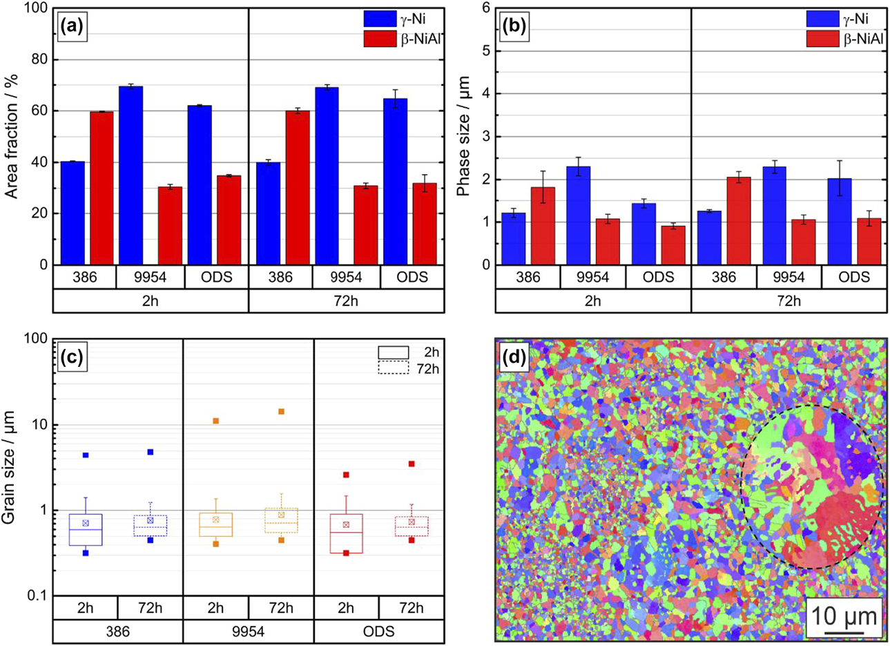
Figure 2: (a) Area fraction of phases and (b) phase size (c) grain sizes of Amdry 386, Amdry 9954 and Amdry 9954 + ODS after a heat treatment of 2 and 72 h at 1100 °C in vacuum before testing and (d) an EBSD mapping of Amdry 9954 with a large unmelted particle due to insufficient homogenization during thermal exposure.
Furthermore, the grain sizes after the first (2 h) and the second heat treatment (72 h) were analyzed, Fig. 2(c). For Amdry 386 and especially for the ODS-containing bond coat, the grain size distribution is broader after a thermal exposure of 2 h compared to the additional second heat treatment of 72 h. After the second heat treatment, all three bond coats show a more homogeneous grain size distribution, resulting in a smaller standard deviation. After the first heat treatment, some unmelted particles, marked with a black dashed line, due to the coating process are still visible, Fig. 2(d). After the second heat treatment, the amount of these unmelted particles is reduced, narrowing the grain size distribution. Furthermore, the coarsening of the smaller grains led to a more homogeneous distribution after the additional heat treatment of 72 h. A few unmelted particles were still observed and were often surrounded by a semicontinuous β-phase layer acting as preferred regions for cracking [Reference Chen28]. Chen et al. investigated the influence of these unmelted particles on the mechanical properties with a similar bond coat Amdry 9951 in compression tests and determined a coarsening rate coefficient for the β-phase up to 1100 °C of 6.49 × 10⁻⁵ µm3/s [Reference Chen28, Reference Chen, Si and McCartney29].
Microtensile creep experiments
Microtensile creep curves were measured for Amdry 386, 9954, and 9954 + ODS at temperatures between 900 and 950 °C, Fig. 3. The Ni-based bond coat Amdry 386 shows a higher creep strength than the Co-based bond coat Amdry 9954 at all temperatures, due to the higher amount of β-NiAl in Amdry 386 compared to Amdry 9954. However, Amdry 9954 with Al2O3-particles reveals the highest creep resistance because the addition of Al2O3-particles to Amdry 9954 outweighs the lower β-NiAl content. The creep minima occurred at all temperatures at a plastic strain of about 0.05–0.1. The slope of the creep curves after the creep minima increases, whereas the strain to failure of the ODS-free bond coats increases with increasing temperature. The long-term heat-treated conditions (1100 °C/72 h) of all bond coats showed a higher creep strength than the short-term heat-treated conditions (1100 °C/2 h). A comparison of the creep minima of the three bond coats at all testing temperatures is shown in Fig. 4(a).
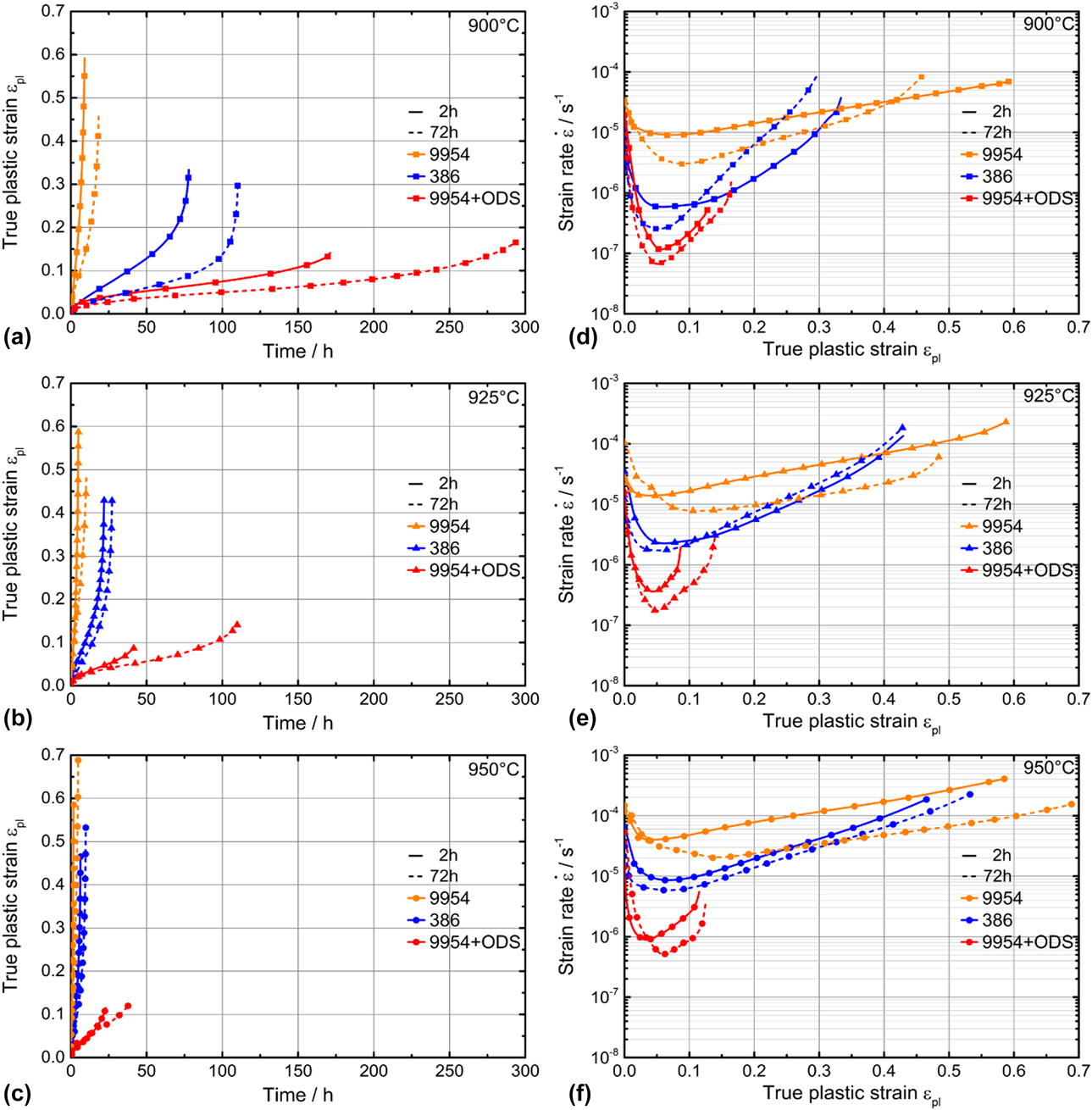
Figure 3: True plastic strain over time plot (a–c) and strain rate over true plastic strain plot (d–f) of Amdry 386, Amdry 9954 and Amdry 9954 + ODS after aging at 1100 °C for 2 h (solid lines) and 72 h (dashed lines) at testing temperatures of 900–950 °C with 15 MPa.
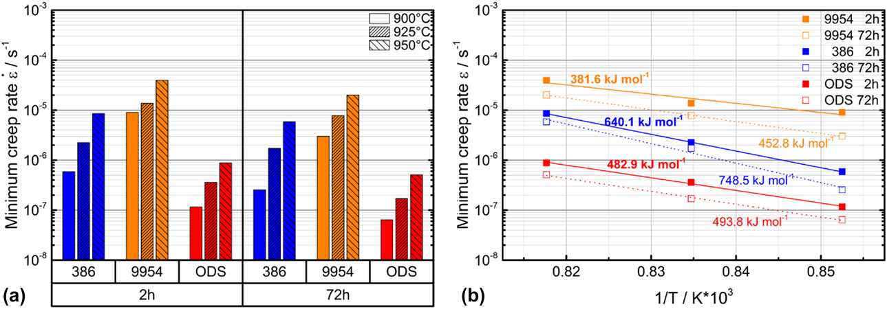
Figure 4: (a) Minima creep rates of Amdry 386, Amdry 9954 and Amdry 9954 + ODS at testing temperatures of 900–950 °C and an applied stress of 15 MPa after a first (2 h) and an additional second (72 h) heat treatment and (b) activation energies of all three bond coats at all testing temperatures.
The differences of the creep minima after different durations of thermal exposure are more pronounced for Amdry 386 compared to Amdry 9954. The lower amount of β-NiAl led to smaller differences for the Co-based bond coat. The equal creep minima for Amdry 386 tested at 950 °C and Amdry 9954 tested at 900 °C are quite similar, which shows the significant influence of the composition and the content of phases in the bond coats. The activation energy of creep for the three bond coats determined by tensile tests between 900 and 950 °C after short- and long-term heat treatment reveals that the activation energy after the additional heat treatment is higher than for the experiments after the short-term heat treatment, Fig. 4(b).
 $$Q = - 2.304 \times R \times {{d\left( {\lg \dot{\varepsilon }} \right)} \over {d\left( {{1 \over T}} \right)}}\quad ,$$
Q is the activation energy, which can be calculated as the slope of the minimum creep rate against the inverse temperature and the gas constant R. Amdry 386 shows the highest activation energy followed by Amdry 9954 + ODS. Amdry 9954 showed the strongest creep deformation at all testing temperatures, which corresponds to the low activation energy of creep.
Microstructure after creep experiments
The microstructure of the tensile specimens of all three bond coats after 72 h of thermal exposure and creep testing at 950 °C at a constant force of 2.35 N until fracture can be seen in Fig. 5. Due to the large plastic deformation, Amdry 386 and especially Amdry 9954 show very ductile fracture behavior. In contrast to 9954, the oxide dispersion strengthened bond coat 9954 + ODS failed more brittle at an earlier state according to a larger diameter of the fracture surface, based on the higher strength and lower ductility of the alloy. Cracks could be observed at phase and grain boundaries between β-NiAl and γ-solid solution inside the samples as well as starting at the surface of the bond coats. The ODS-particles are equally distributed in the β-NiAl phase and the γ-solid solution for Amdry 9954 + ODS.
Figure 5: BSE images of the microstructures of Amdry 386 (a + b), 9954 (c + d) and 9954 + ODS (e + f) after 72 h of thermal exposure and microtensile creep tests at 950 °C.
The grain size of all bond coats was analyzed by EBSD after heat treatment of 72 h at 1100 °C and after the same heat treatment and microtensile tests at 950 °C, Fig. 6(a). All bond coats show an increase in their grain size after tensile testing. This increase occurred due to normal grain coarsening during the creep test. The ODS bond coat showed smaller grain sizes before and after tensile tests compared to the ODS-free coatings but did not prevent grain coarsening. In addition to the grain size, Fig. 6(b) shows the size of the γ-Ni phase and β-NiAl phase for all bond coats after the creep experiments at 950 °C after the short-term (1100 °C/2 h) and the long-term (1100 °C/72 h) heat treatment. The additional long-term heat treatment leads to a much stronger increase of the phase sizes of all three bond coats compared to the initial state, see Fig. 2(b). It is also noticeable that the addition of ODS-particles does not lead to a significant prevention of phase coarsening.
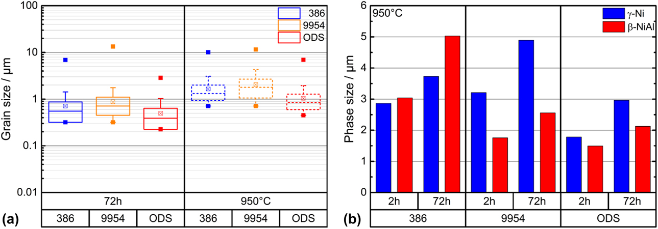
Figure 6: Grain sizes of Amdry 386, Amdry 9954 and Amdry 9954 + ODS (a) after 72 h of thermal exposure and after the same heat treatment and microtensile tests at 950 °C and (b) phase sizes after microtensile creep tests at 950 °C heat treated for 2 and 72 h at 1100 °C in vacuum.
To investigate the arrangement of the grains depending on their size before and after microtensile tests, grain sizes smaller than the median grain sizes of Amdry 386 and Amdry 9954 + ODS were pigmented in red, Fig. 7. Therefore, the microstructures of these samples were analyzed along the loading axis by EBSD measurements. After the additional heat treatment of 72 h and before the creep experiment, the median grain size was 0.6 µm for Amdry 386 and 0.45 µm for the ODS-containing bond coat and grains smaller than the median were found all over the specimen. Accumulation of areas with smaller grains, especially for Amdry 386, could be observed. Figure 7(b) shows the coarsening of the grains due to the time and temperature during the creep test. The median grain size after the creep tests was about 1.55 µm for Amdry 386 and 0.8 µm for the ODS-containing bond coat. It can clearly be seen that for Amdry 386, the smaller grains are mainly elongated along the loading axis, separated by layers of larger grains. In contrast to that, no preferential accumulation of smaller grains could be observed for the ODS-containing bond coat, Fig. 7(d).
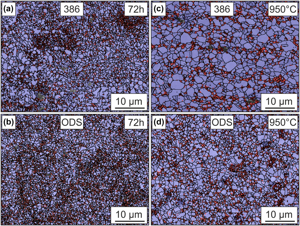
Figure 7: EBSD measurements after thermal exposure of 72 h of (a) Amdry 386 and (b) Amdry 9954 + ODS. EBSD measurements after the same heat treatment and microtensile tests at 950 °C for (c) Amdry 386 and (d) Amdry 9954 + ODS. Grains smaller than the median grain sizes (red) and grains larger than the medium grain size (purple).
Discussion
In this work, microtensile tests on three different MCrAlY-bond coats after heat treatments of 2 and 72 h at 1100 °C were performed in the temperature range between 900 and 950 °C. The second heat treatment led to grain coarsening, resulting in lower creep rate minima during all experiments. The higher β-NiAl amount of Amdry 386 is responsible for the superior creep properties in comparison to Amdry 9954, which contains less β-NiAl and therefore more γ-solid-solution phase. This is due to the higher creep strength of NiAl, as compared to Ni at temperatures above 900 °C, which was investigated in previous studies [Reference Raj30, Reference Karashima, Oikawa and Motomiya31, Reference Raj32, Reference ur Rehman, Durst, Neumeier, Sato, Reed and Göken33]. Moreover, the higher yttrium content in Amdry 386 leads to a higher amount of small Y2O3-particles during plasma spraying. These nanoscale oxides resulted in an additional hindering effect for deformation. After the tensile creep experiments, an increase of the size of the γ-solid-solution phase, β-NiAl phase and the ODS-particles was observed. The grain size of all tested conditions increased slightly. However, an inhomogeneous grain coarsening of the grains took place in the ODS-free bond coat. After testing, EBSD measurements revealed layers of grains smaller and larger than the median grain size which were aligned along the loading axis of Amdry 386 and Amdry 9954. This alternately layered structure occurred presumably due to the formation of small oxides during the manufacturing process. The deformation mechanism in this stress temperature regime should be grain boundary sliding, as described in former studies by Hebsur [Reference Hebsur and Miner34]. However, due to the high activation energies of the bond coats, determined at this work, dislocation creep is suggested to be the dominant deformation mechanism.
The superior creep resistance of Amdry 9954 + ODS in comparison to the dispersoid-free Amdry 9954 can be explained by the detailed investigations of Arzt et al. on the addition of 2 at.% of yttria particles in NiAl with similar fine grain size compared to our bond coats [Reference Arzt and Grahle16, Reference Arzt, Behr, Göhring, Grahle and Mason17]. It is assumed that the nanoscaled oxides Al2O3 particles provide a similar beneficial effect of dispersion strengthening and hinder the dislocation motion. This results in a higher activation energy, but also leads to a much lower plastic strain to failure.
Conclusion
Small-scale tensile creep experiments have been performed on three freestanding MCrAlY bond coats using a TMA. To investigate the mechanical properties of the bond coats independent of the substrate, small cylindrical tensile specimens with a precise and reproducible shape were fabricated by grinding and polishing to a diameter of 450 µm. Force-controlled creep experiments were performed at temperatures between 900 and 950 °C under constant Ar-flow at a constant load of 2.35 N. The higher amount of β-NiAl in the Ni-based bond coat Amdry 386 led to superior creep properties in comparison to the Co-based bond coat Amdry 9954. A longer annealing heat treatment of 72 h compared to 2 h at 1100 °C led to lower creep rates for all three bond coats at all testing temperatures due to grain coarsening of both phases. The main deformation mechanism for Amdry 386 and Amdry 9954 could be determined as dislocation creep. The addition of ODS particles in Amdry 9954 led to a significant decrease of the creep rate due to the additional interaction between the dislocation and the oxide particles. The strain to failure decreases from around 0.6 for Amdry 9954 to 0.14 for Amdry 9954 + ODS.
Methodology
Material
Three MCrAlY bond coats were investigated in this study. An Ni-based NiCoCrAlY (Amdry 386) and two Co-based CoNiCrAlY (Amdry 9954) bond coats. One of the Co-based bond coats contains additional 2 wt% of Al2O3 for oxide dispersion strengthening (ODS) (Amdry 9954 + ODS) produced by mechanical alloying [Reference Bergholz, Pint, Unocic and Vaßen36]. The chemical compositions are listed in Table I.
TABLE I: Composition of Amdry 386 and Amdry 9954 (+ODS) in at.%.
Coatings with a thickness of approximately 3 mm were produced by low-pressure plasma spraying using a F4 torch in an Oerlikon Metco (Wohlen, Switzerland) facility on a steel substrate. Afterwards, plates of 20 × 10 × 2 mm in size were spark eroded out of the coating layer and heat treated in argon atmosphere at 1100 °C for 2 h. Then, half of the samples got an additional heat treatment for 72 h under equal conditions to investigate the influence of thermal exposure. The porosity of the samples in the as-sprayed conditions was about 0.55 ± 0.14% and decreases after the first heat treatment of 2 h at 1100 °C to 0.2 ± 0.08%. No significant change of the porosity was to be observed after the additional heat treatment.
Sample preparation
The specimens were cut with a precision wet abrasive cutting machine Brillant 220 from ATM to a width of about 550 µm. For the preparation of a small circular microtensile specimen out of the rectangular shape, a further step was necessary. The challenge of producing microtensile specimens, especially of dimensions below 1 mm, is that notches across the gauge length and an inhomogeneous sample thickness can have a much larger influence on the experimental results, as with standard tensile specimens on the macroscale. This means that the cross section, no matter if it is rectangular or circular, must be well known and reproducible for all samples. Common fabrication techniques for rectangular tensile specimens are mechanical milling or electrical discharge machining methods [Reference Kumar, Singh, Singh and Sethi37, Reference Lee, Lim, Narayanan and Venkatesh38]. Samples with rectangular cross sections are commonly used for macroscopic testing. In the submillimeter range, the sample edges of rectangular-shaped samples are rounded. This results in inaccurate determinations of the cross section and edges that are preferential sites for notches because of insufficient grinding and polishing. To eliminate the influence of varying geometries and to prove the reliability and reproducibly of the tensile tests on the submillimeter scale, the use of samples with circular cross sections is more suitable. To produce specimens with circular cross sections without notches and high accuracy, the sliced samples were prepared by a high-precision grinding and polishing process at Microsample GmbH, specialized to produce circular samples with diameters smaller than 1 mm. The specimen is fixed in a specimen holder with two grips. A liquid cooling system prevents any heat influence during milling with a diamond wire wheel. The desired gauge length can be adjusted before tailoring the sample. During grinding, the sample holder rotates synchronic to prevent any torsion effect in the sample and is mounted perpendicular to the rotation axis of the grinding wheel. The measurement of the sample diameter is monitored at high speed and high precision with a 2D optical micrometer system. After grinding, further polishing steps are performed to smoothen the sample surface, removing the thin mechanically affected zone of the grinding process and reducing notches [Reference Rathmayr, Bachmaier and Pippan27, Reference Rathmayr, Hohenwarter and Pippan39]. The cross section was determined to be 450 ± 2 µm in diameter, over the entire gauge length of 2500 µm. The surface roughness of 2 µm was determined by a VHX-1000-laser microscope from Keyence, Osaka, Japan.
Microstructural analysis before and after testing was carried out with a Zeiss Crossbeam 540 (Oberkochen, Germany) using back-scattered electron imaging (BSE). The area fraction, as well as the phase and grain size of the individual phases, was determined by electron backscatter diffraction (EBSD) with the software ATZEC from Oxford Instruments, Abingdon, U.K. Longitudinally polished sections of the tested specimens after the tensile creep experiments were analyzed by the software ImageJ in horizontal direction 250 µm away from the crack tip.
TMA
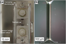
The microtensile creep tests were performed in a SiC furnace of a thermomechanical analyzer type 402 F3 Hyperion from Netzsch, Selb, Germany. The advantage of this setup is a very accurate, controllable force and length resolution during the creep tests. The force sensor has a digital resolution smaller than 0.01 mN and a force range from 1 mN to a maximum of 3 N. Therefore, testing of small samples or thin coatings in the conditions, which are commonly used during service, can be investigated. The change in length of the sample is measured accurately by an inductive linear variable displacement transducer (LVDT) with a digital resolution of 1.25 nm and a maximum change in length of 4 mm. During the tests, the measuring system is thermally stabilized by water cooling. Hebsur et al. studied NiCoCrAlY bond coats, which were tested in vacuum and air between 660 and 850 °C [Reference Hebsur and Miner8]. The negative effect of oxygen on NiCoCrAlY bond coats led to blunting of initial surface pores during testing. Hence, in this work, a constant argon gas flow was applied to prevent oxidation of the samples. Creep tests were performed at 900, 925, and 950 °C under a constant argon flow of about 200 mL/min. Before testing, the samples were heated up with 5 K/min under a constant load of 50 mN to fix the specimen until the testing temperature is achieved. A holding period of 2 h was used to achieve thermal equilibrium of the whole setup. The TMA is a load controlled setup in which the load was increased within 1 min from 50 mN to a constant load of 2.35 N over the whole test duration after the holding period. In respect to the sample’s diameter of 450 µm, this led to a stress of 15 MPa at the beginning of the tests. The sample holder and the pushrod are made of fused silica, which is thermally stable up to 1100 °C. The clamping jaws with the hexagonal bolts and nuts, as well as the upper parts of the clamp with a ground cutting edge for mounting the sample, are made of alumina. The TMA setup and a microtensile specimen before testing are shown in Fig. 8.
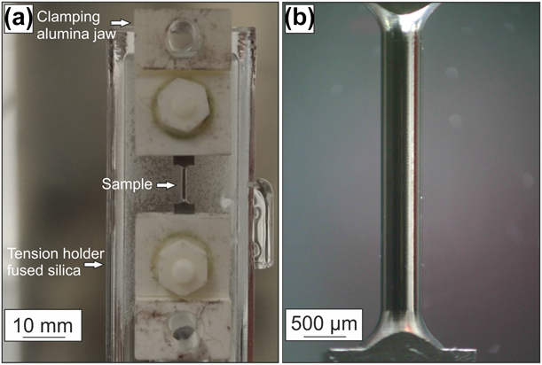
Figure 8: (a) TMA setup with fused silica tension holder, pushrod and clamping jaw made of alumina for mounting the (b) polished tensile specimen before creep testing with a diameter of 450 ± 2 µm over the entire gauge length of 2500 µm.
Acknowledgments
The authors would like to acknowledge Dr. Georg Rathmayr from Microsample GmbH for manufacturing the microtensile specimens. The authors acknowledge funding by the Deutsche Forschungsgemeinschaft (DFG) through projects A6 and B6 of the collaborative research center SFB/TR 103 “From Atoms to Turbine Blades-a Scientific Approach for Developing the Next Generation of Single Crystal Superalloys.”


 Open access