


I. INTRODUCTION
BepiColombo ESA mission (http://sci.esa.int/bepicolombo/) has the goal of observing and studying Mercury and its surroundings. It has been identified as one of the most challenging planetary projects, since the proximity to the Sun binds some of the subsystems to withstand temperatures over 500°C. Although the whole spacecraft operates in a very harsh environment from temperature and radiation standpoints, this fact becomes critical for the subsystems installed outside the spacecraft. One of them is the Antenna Subsystem, on which this paper is focused.
This paper describes the set-up and test procedure and results of the Medium Gain Antenna Major Assembly (MGAMA) radiation test in temperature. This antenna is an X-band two-axis steerable dual-flare horn with a 2.5 m long boom, which provides two-way communications between the spacecraft and Earth in safe mode and during interplanetary cruise phase.
This paper is divided in the following sections: Section II provides an overview of MGA and its components, Section III explains the test plan, Section IV the test set-up, and Section V the test results. Finally, Section VI includes the conclusions of the presented work.
The Medium Gain Antenna Radiofrequency Assembly (MGA-RFA) measurements hereafter presented were acquired in the near-field planar scanner of the LEHA-UPM facilities (Antenna Measurement Laboratory of Technical University of Madrid) in Madrid, Spain.
II. MEDIUM GAIN ANTENNA OVERVIEW
The MGAMA, whose Engineering and Qualification Model (EQM) is shown in Fig. 1, works as backup of the High Gain Antenna and also as primary communication link at several conditions of the cruise to Mercury and the mission phase, such as safe mode operation. The safe mode shuts down all subsystem except critical ones such as attitude, control, thermal management, or communications. This mode is usually automatically triggered by the spacecraft to prevent damage or complete loss when a potentially harmful event, which can jeopardize the mission, occurs.
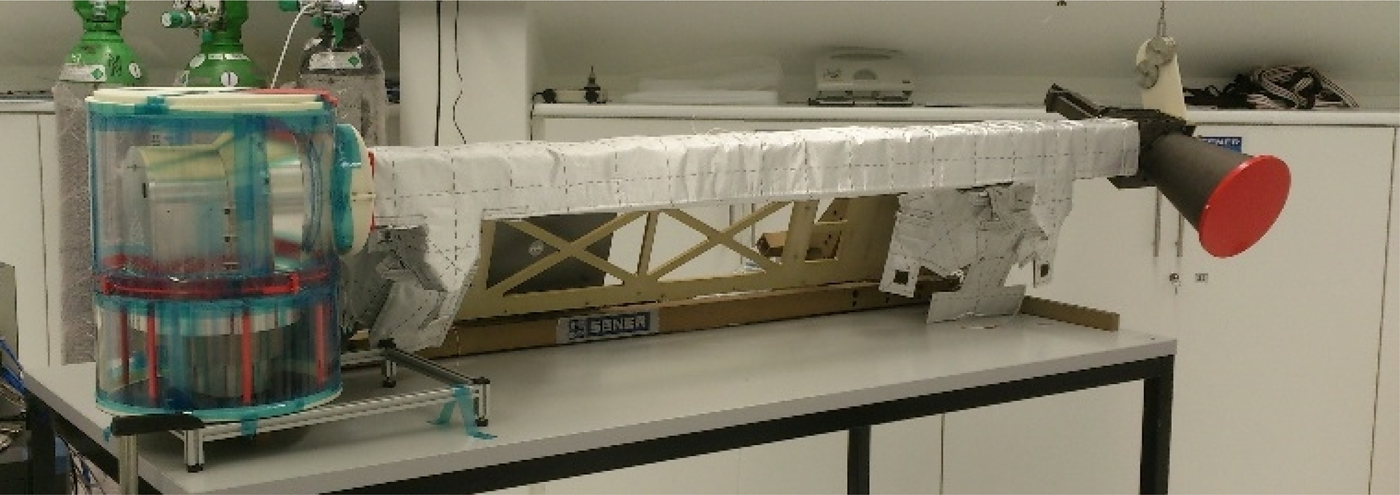
Fig. 1. BepiColombo MGAMA EQM.
SENER is responsible for the delivery of MGAMA assembly, integration and test, and also is the design authority of the Antenna Pointing Mechanism (APM), MGAMA boom, Hold Down Release Mechanism, and APM Electronics. The radiofrequency assembly (which includes boom waveguides and horn antenna) is designed and manufactured by TRYO AEROSPACE. The MGA Rotary Joint Assembly (RJA) is responsibility of COBHAM. In order to minimize overall insertion loss, both RFA waveguides and the whole RJA are manufactured in silver and gold-plated titanium, respectively.
The MGA-RFA, which is shown in Fig. 2, is composed of the hereafter listed components. In order to properly withstand the extreme thermal environment of Mercury, all of them are made Ti6Al4 V titanium alloy, which presents outstanding thermal and mechanical properties for space applications.
-
• Dual-flare horn: Rotational symmetric horn antenna which is able to provide both the required gain coverage and good axial ratio. This can be observed in Fig. 3.
-
• Septum set: This block is composed by the septum polarizer itself, a mitred corner and a transition to WR-112 standard waveguide. It transforms incident TE10 mode from WR-112 rectangular waveguide into two orthogonal TE01 and TE10 modes in a square waveguide in phase quadrature, which compose the desired circular polarization. This can be observed in Fig. 3.
-
• Waveguide routing: It connects the septum set and dual-flare horn to the dual-axis RJA which is placed in the MGA-APM. It is composed by several rectangular straight waveguides, bends, and a twist.

Fig. 2. RFA Engineering Qualification Model with structural boom.
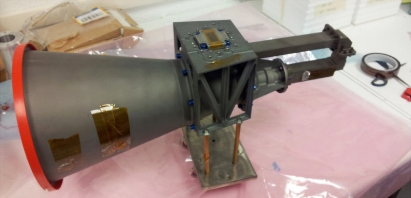
Fig. 3. RFA dual-flare horn and septum set.
III. MGA TEST PLAN
From the engineering perspective, one of the most challenging points of BepiColombo mission is to withstand the extremely demanding thermal environment of Mercury. This is considered in the design of almost all the spacecraft subsystems, although it becomes especially critical in the case of those instruments and systems that are directly exposed to solar flux, like the Antenna Subsystem. Consequently, as part of the qualification campaign of the equipment, it was necessary to quantify and evaluate how the RF performances would evolve as function of conductivity variations and thermal distortions in a representative thermal environment. Thus, both the return loss and the radiation pattern should be characterized in temperature.
The MGA-RFA was thermally cycled and the return and insertion loss of the boom waveguides measured in temperature. This thermal cycling is performed in high-vacuum conditions in order to reproduce space environment and prevent oxidation of the silver-plated parts. Fast oxidation emerges with the combination of high temperature and oxygen. Consequently, performing radiation pattern measurements in temperature requires an inert atmosphere with as few oxygen as possible. In addition, since maximum operating temperature of the antenna is expected to be over 530°C, and it is extremely difficult to heat up the antenna to that temperature and simultaneously perform radiation measurements, an alternative approach was adopted. The antenna is heated up to a lower and more feasible temperature and measured in the Planar Near-Field System, being the results compared with those obtained via analysis at that temperature by TRYO AEROSPACE. This analysis is based on a Compact Test Range measurement at ambient temperature, to which the results of thermal analysis have been added. If good correlation is found between measurement in temperature and analysis performed by TRYO, then accurate extrapolations of the RF behavior can be made for higher temperatures and validate the performance of the antenna within the full specified thermal range. In order to provide an accurate extrapolation of the thermal behavior of the RFA, measurements were performed at the six most significant frequencies: 7145, 7165 and 7190 MHz at uplink band; and 8400, 8425 and 8450 MHz at downlink band. The maximum test temperature was initially set to 200°C. However, due to thermal limitations of the subminiature version A connector (SMA) cables used, the maximum temperature of the test was finally set to 150°C. This temperature is considered high enough to accurately extrapolate antenna performance at maximum foreseen operating temperature (over 530°C), and verify correlation with results obtained by analysis. Measurements were performed at ambient room temperature (23°C), 100, 120, and 150°C. Radiation patterns were acquired within a ±60° angular range. Voltage standing wave ratio (VSWR) was also monitored.
IV. MGA TEST SETUP
As it was mentioned before, the MGA was measured in the antenna measurement facilities of the UPM in Madrid (http://www.gr.ssr.upm.es/leha/). Since heating up the entire anechoic chamber is not possible due to its dimensions and in order to reproduce the required thermal environment in an inert atmosphere, an alternative solution was developed: to design, manufacture, and build a hermetic, thermal box with a transparent RF window – called from now on “oven” for the sake of simplicity – where the full RFA (including boom waveguides and horn) could be installed, isolated from the rest of the anechoic chamber. This allows heating up the assembly without inducing distortions from the set up. In addition, and in order to correctly perform radiation pattern measurements, the oven should allow RF propagation through the frontal area of the horn; hence, a RF transparent window was implemented. The oven and MGA position inside is depicted in Fig. 4.
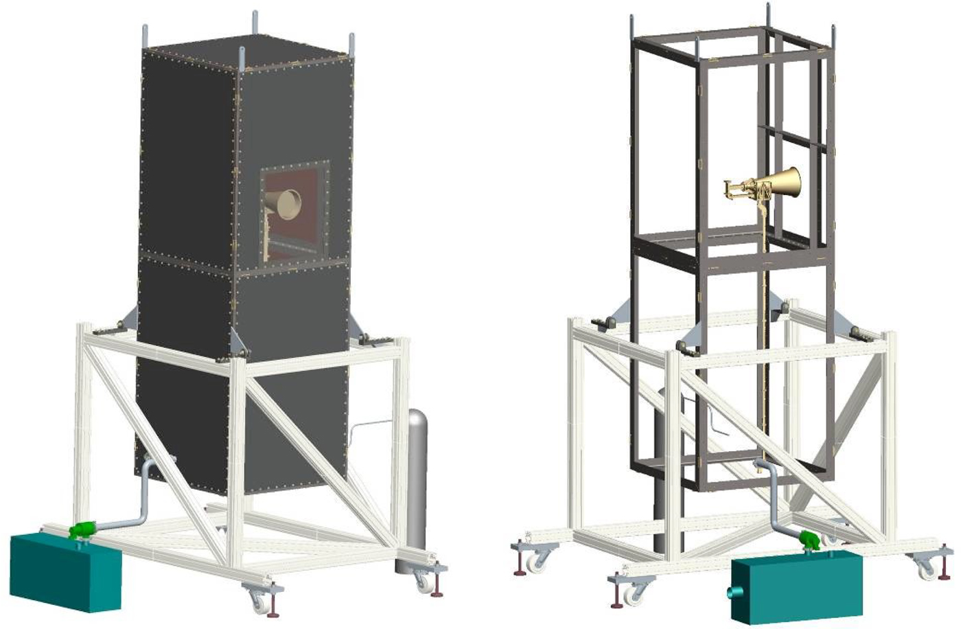
Fig. 4. RF oven overview (left) and its structure with MGA-RFA placement (right).
The internal dimensions of the oven are 3 m × 1 m × 1 m. The structure is made of stainless steel and divided into two well-differenced areas. The upper one encloses the dual-flare horn and septum polarizer, which are made of bare titanium, while the lower one contains boom waveguides, which are made of silver-plated titanium.
As mentioned before, it is known that silver coating presents fast oxidation with high temperatures. In order to prevent this effect, an inert atmosphere was necessary in the lower part of the oven, where the silver-plated waveguides were placed (<2% of oxygen is requested at 150°C). Oxygen is removed with a vacuum pump, and replaced by Argon. This area is mechanically sealed from outside and the upper part of the oven with two Teflon gaskets of 1 mm thickness, which allow RF propagation. The gaskets are tightly fastened between waveguide flanges at the boundaries of the lower part of the oven. One of the gaskets is installed in the interface of boom waveguide with external set up (in the lower part of the box). The other is placed in the interface between boom waveguide and horn and septum set (which are placed in the upper part). This avoids the air entering into the silver-plated titanium waveguide and also Argon leakages from the lower part of the oven. The effect of the Teflon gasket in the RF propagation was characterized and taken into account in the measurements.
In one of the walls of the upper area, in front of the horn aperture, a Kapton RF transparent window with dimensions of 600 mm × 500 mm was placed. This makes performing antenna measurements possible while keeping the required hermetic and thermal environment inside. The rest of the oven internal walls are metallic.
The horn is located inside this part in an isostatic supporting configuration, and held by tensors, as shown in Fig. 5. The Teflon gasket which separates both sections is installed in a stainless steel flexible dish, which ensures high stability in position with respect to temperature without imposing disturbances from the oven to the AUT. The length of the tensors can be regulated to adjust location of the horn and preload.
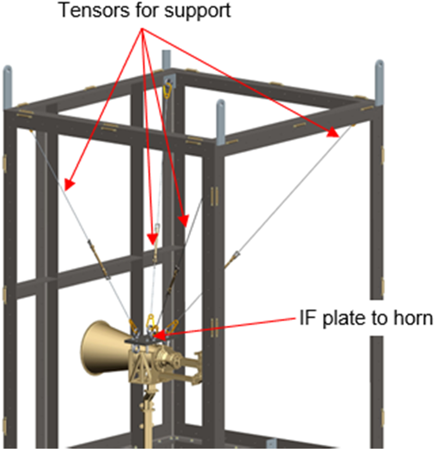
Fig. 5. Detail of the tensors.
Both sections of the oven are heated by electrical resistors, adequately dimensioned to provide enough power to heat the full assembly and keep temperature constant during radiation pattern measurements.
The bottom of the RF oven has a stainless steel flexible circular plate in order to correctly attach the antenna under test to the external measurement RF waveguide. This provides thermal isolation and absorbing boom dilations due to temperature increase.
A short titanium waveguide section is placed between the RF oven outer wall and a final stainless steel straight waveguide with UBR 84 flange, in order to avoid excessive heating of measurement RF test cables.
The outer side is covered with thermal insulating panels (except the RF window), which minimizes thermal losses and makes it easier to keep the oven at the commanded temperature. This also makes it possible to lower the temperature of the outer walls enough to attach RF absorbers to them. In this way, RF reflections and re-radiations due to the oven influence are minimized. This is achieved by covering with RF absorber material the metallic face of the oven which is in front of the measurement probe. The reflectivity of this absorber must be lower than −20 dB in order to avoid reflecting signals reaching the probe and distorting the measurements.
Figure 6 shows the RF set-up installed in the Planar Near-Field System of the Technical University of Madrid prior to the installation of the Kapton RF window and RF absorbers.

Fig. 6. Overview of RF oven placed in front of planar system.
The detail of RF absorbers placed in front of the measurement probe and the placement of the oven inside the LEHA-UPM anechoic chamber can be respectively observed in Figs 7 and 8.

Fig. 7. Planar system probe (left), front part of RF oven covered by absorbers and RFA placed in the aperture of RF window (right). RF window was removed for the picture.

Fig. 8. Overview of RF oven placed in front of planar system.
V. MGA TEST RESULTS
In this section, the results obtained during the test are provided. Since radiation and VSWR measurements were acquired, the following parameters were obtained: co-polar and cross-polar radiation patterns within θ < 60° angle, peak gain, return loss, and 3 dB beamwidth.
A) Return loss
The return loss was acquired at several temperatures: 22, 60, 100, and 150°C. Figure 9 depicts how return loss curve evolves with respect to temperature.
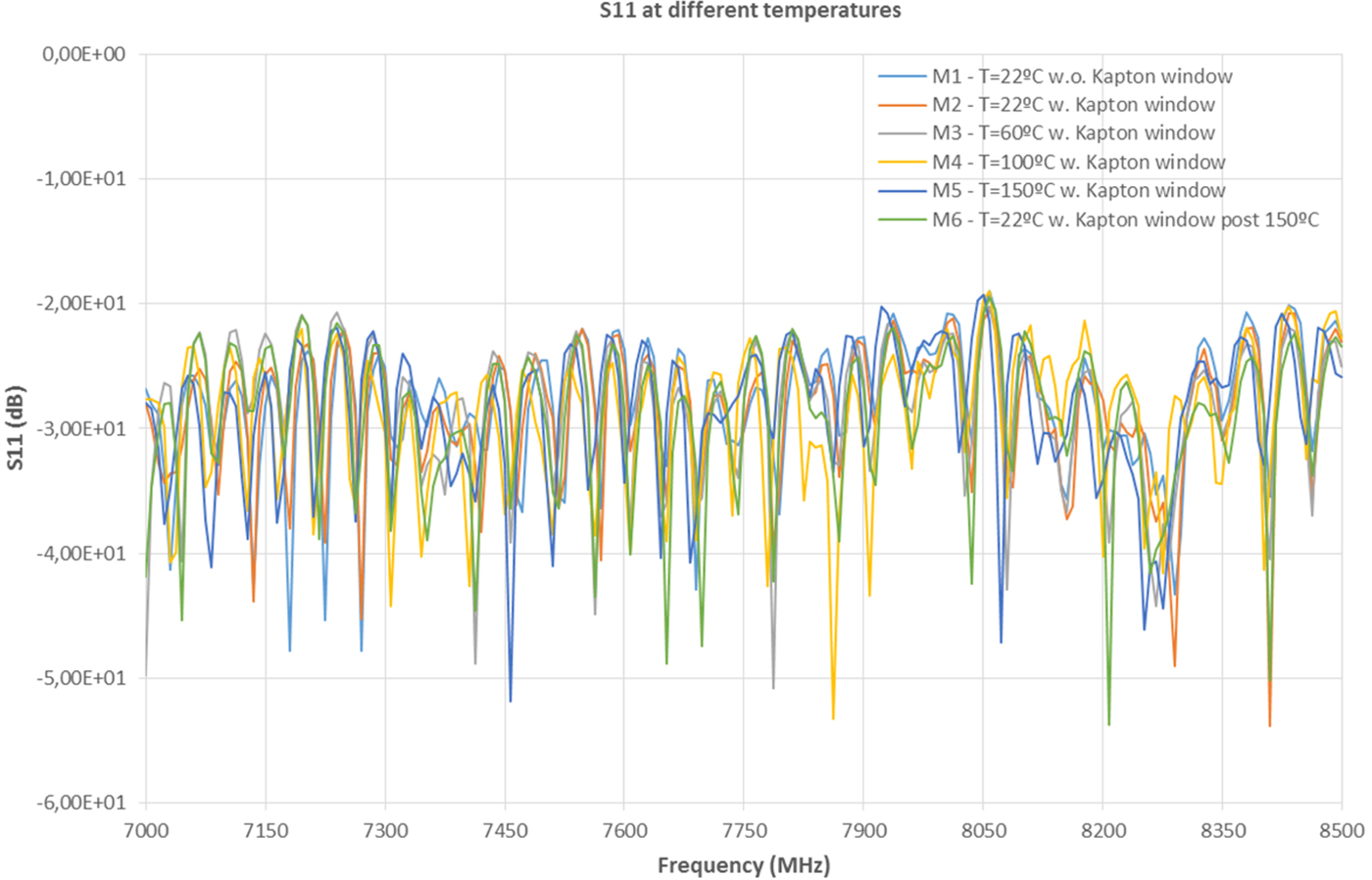
Fig. 9. MGA-RFA S 11 in temperature.
As it can be observed in the top of the ripples of the curves, the thermal expansion of the antenna shifts the response to the left very slightly. This behavior shows good correlation with analysis and is considered normal, since dilation due to higher temperatures makes the antenna electrically bigger. It is worth to remark that the shown return loss results are conditioned by the two Teflon gaskets inserted in the boom waveguide that isolates silver-plated parts from the rest of the set-up. RFA return loss response without gasket is better than 28 dB for the entire specified bandwidth. Despite this difference, the aim of the test is to observe the degradation of a thermal distorted antenna w.r.t. ambient temperature, which is observed in Fig. 9.
B) Gain
Table 1 shows some of the gain figures of the MGA antenna [1, Reference Evans2]. They are compared with the ones obtained by the Antenna Manufacturer (TRYO AEROSPACE) as result of an extrapolation in temperature.
Table 1. Antenna gain measurement results (22, 60, 100, 120, and 150°C).
Peak gain shows good correlation between values that were obtained via analysis. These figures come from measurements at Compact Range of TRYO where a gain delta coming from thermal analysis is added to the measured value. Values obtained with the RF oven test set-up and extrapolated by TRYO show a standard deviation between both of them of around 0.15 dB, which is approximately the uncertainty associated to the used planar system.
Figure 10 shows the gain delta between measurements in the RF oven measurement at 22°C the rest of measurements at different temperatures. The abscissa axis is sorted as follows:
-
• Measurement 1 (M1): Measurement at 22°C without Kapton RF window. This measurement establishes direct correlation with Compact Range measurements of TRYO.
-
• Measurement 2 (M2): Measurement at 22°C with Kapton RF window. This set-up is the one to be used at high temperatures. From difference between M2 and M1, the influence of the Kapton foil can be obtained, which is considered negligible since it is much lower than planar scanner uncertainty.
-
• Measurement 3 (M3): Measurement at 60°C with Kapton RF window.
-
• Measurement 4 (M4): Measurement at 100°C with Kapton RF window.
-
• Measurement 5 (M5): Measurement at 150°C with Kapton RF window.
-
• Measurement 7 (M6): Measurement at 22°C with Kapton RF window post-thermal test.
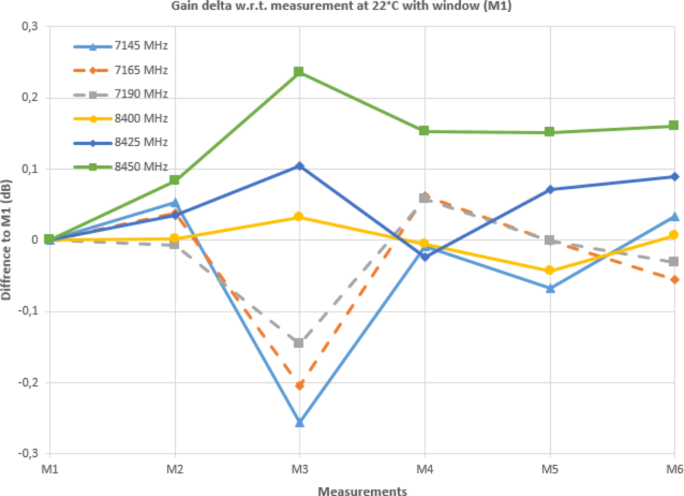
Fig. 10. The delta gain between RF oven measurements and TRYO extrapolations.
From Fig. 10 it is observed that maximum gain variation w.r.t. to temperature is <±0.3 dB up to 150°C. If the uncertainties of near-field planar and Compact Range systems are taken into account in this figure, which is between 0.15 and 0.2 dB at MGA operating frequencies, the resultant variation of antenna gain at high temperature is minor.
These data are significant enough for verifying that no critical degradations in the gain figure will appear at higher temperatures.
C) Radiation pattern
In addition to VSWR and peak gain, thermal distortion will have impact on the shape of the radiation pattern, changing the antenna performance not only at the direction where it is pointed but also at off-boresight angles. Figures 11 and 12 provide a comparison at 7.165 and 8.425 GHz – central frequencies of RX and TX bands – respectively of the measurements acquired at different temperatures for both CP and XP components.
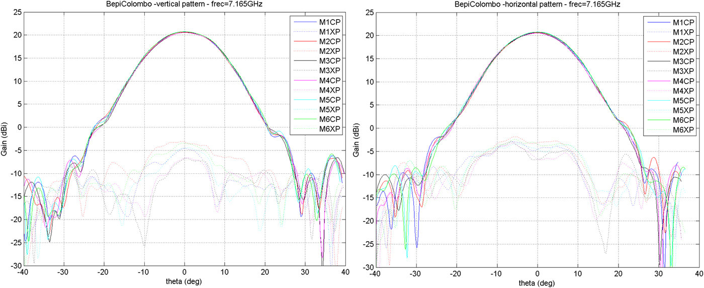
Fig. 11. Radiation pattern at 7.165 GHz. Vertical (left) and horizontal (right) cuts.

Fig. 12. Radiation pattern at 8.425 GHz. Vertical (left) and horizontal (right) cuts.
Radiation pattern shapes remain almost completely constant in the surroundings of the boresight. Greater differences are observed between different temperatures for angles >20°, where directivity is below −20 dB of its maximum value. Cross-polar radiation pattern also shows very slight variations at high temperatures, although they remain below levels that do not jeopardize the performance of the antenna. It can be also observed in Figs 11 and 12 that the pointing direction of the antenna remains practically constant.
D) The 3 dB beamwidth
Lastly, the 3 dB beamwidth of the antenna through the different measurements is also presented. Since radiation pattern shape changes with temperature, the 3 dB beamwidth will be consequently also affected.
Figure 13 shows the evolution of beamwidth at the six measured frequencies. It is observed that, as far as radiation patterns keep its shape almost constant at high temperature, 3 dB beamwidth also remains almost without changes.
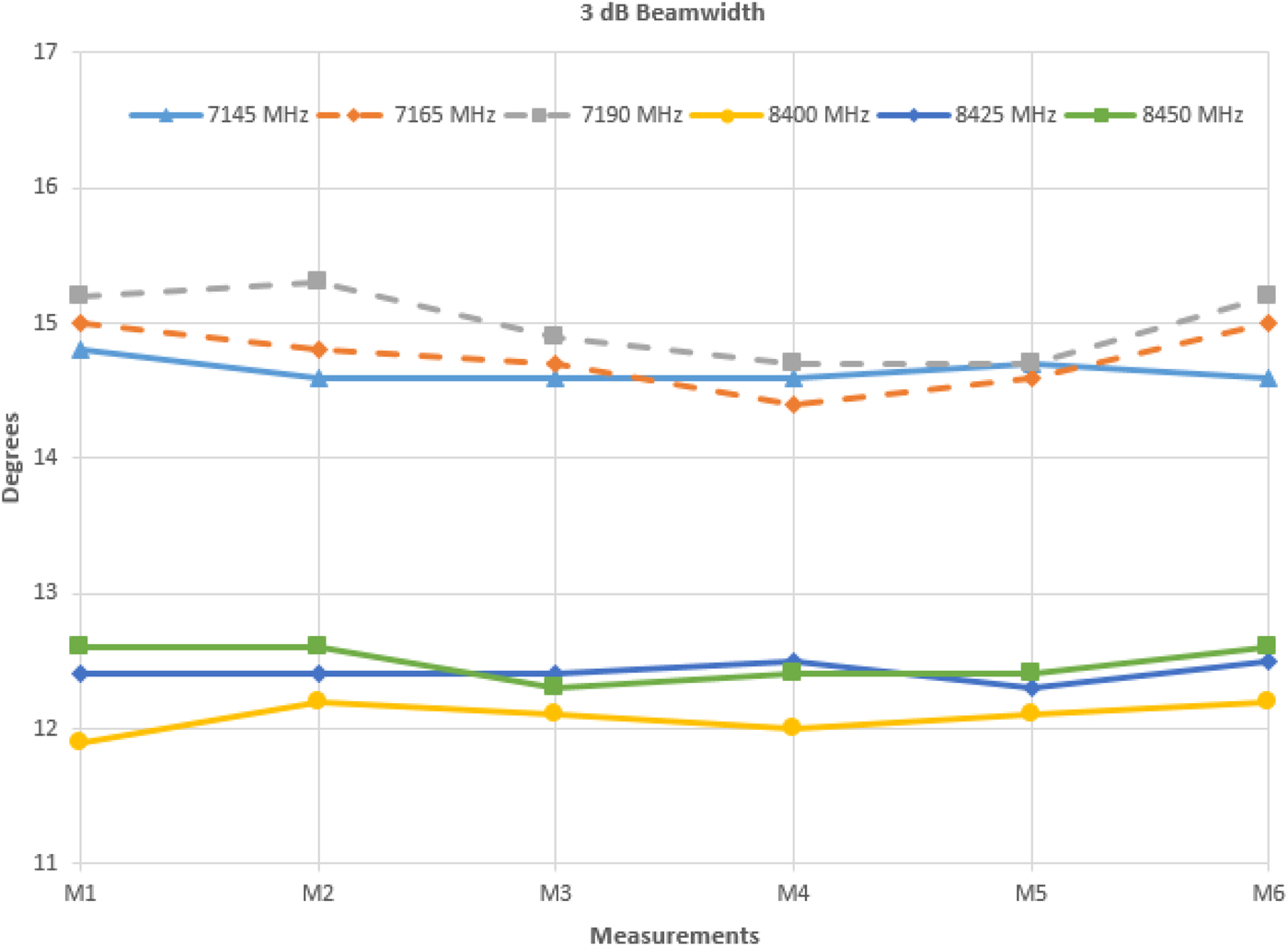
Fig. 13. BepiColombo MGA-RFA 3 dB beamwidth in temperature.
As it can be observed in the previous paragraphs, although the antenna is made of a very thermally stable titanium alloy (Ti6Al4 V), which has outstanding mechanical and thermal properties for space applications, high temperatures slightly degrade the overall performance of the antenna. However, it can be also noticed that none of the observed RF parameters has been significantly affected. In addition, the good correlation between measured results in the RF oven and extrapolations via analysis provided by TRYO up to 150°C ensure that not relevant differences can appear at temperatures as high as 530°C.
Therefore and based on these observations, no critical degradations are expected neither in the maximum gain figure nor radiation pattern within the specified thermal range.
IV. CONCLUSION
MGA-RFA EQM completed successfully the above described test as part of the qualification campaign. The assumptions for high temperatures that were based on analysis and extrapolations from Compact Range measurements were validated. Proper performance of the antenna in the full mission environment is ensured thanks to the environment simulation set-up. For now, MGA-RFA PFM successfully passed its acceptance campaign, being delivered to SENER for its integration with the rest of the MGAMA PFM. The full MGAMA PFM has also successfully passed its acceptance campaign, which includes a VSWR test while deploying the antenna using a zero gravity device. MGAMA PFM has been currently delivered to Thales Alenia Space, Italy, for the rest of its integration in BepiColombo MPO and verification at spacecraft level in ESA ESTEC facilities (the Netherlands).
 Victor Sanchez was born in 1988 in Leganes (Madrid), Spain. He obtained his Bachelor of Science degree in Telecommunication Systems at Universidad Carlos III de Madrid (UC3M, Madrid) in 2010 and his Telecommunication Engineering degree at Universidad Politécnica de Madrid (UPM) in 2013. He is radiofrequency engineer at SENER Ingeniería y Sistemas S.A. since 2012, designing and testing different components of steerable antenna systems for several European Space programs such as BepiColombo, Solar Orbiter and Euclid. He is currently coursing his PhD degree at UPM.
 Fernando Martin was born in 1978 in Madrid. He obtained both his Telecommunication Engineering and PhD degrees at Universidad Politécnica de Madrid (UPM) in 2002 and 2009 respectively. He has wide experience in the design of measurement systems for large RADAR antennas. He worked as radiofrequency engineer at Indra Sistemas. Since 2010, he is at SENER Ingeniería y Sistemas S.A. as Radiofrequency engineer and responsible of antenna subsystems for several European Space programs such as BepiColombo, Solar Orbiter and PROBA3. He has also participated in the design of defence communication systems.
 Aingeru Barrio obtained his mechanical engineer degree at Universidad del País Vasco (UPV/EHU). He is mechanical engineer at SENER Ingeniería y Sistemas S.A., having expertise in different types of actuators and more specifically in antenna pointing mechanisms (APMs). He has participated in the mechanical design of antenna subsystems for European Space programs such as BepiColombo and Jupiter Icy Moons Explorer (JUICE).
 Iñaki Pinto was born in Bilbao in 1978. He obtained his degree in Mechanical Engineering and coursed a General Management Program at Universidad del País Vasco (UPM/EHU) and Universidad de Deusto respectively. He has been mechanical engineer at ITP and Rolls-Royce. He is at SENER Ingeniería y Sistemas since 2006, being project manager since 2012. He has participated in several European Space missions such as GAIA, BepiColombo, Solar Orbiter and more recently JUICE.
 Rafael García received his degree in Telecommunication Engineering from Universidad Politécnica de Madrid (UPM) and also from Chalmers University of Göteborg (Sweden) in 2004. He is currently at TRYO Aerospace since 2006 as Principal Electrical Engineer. He has industrial experience in different areas of electrical engineering such as designing, testing and tuning satellite microwave components, which include feed antennas, filters, output multiplexers, and OMTs for Telecomunications Satellites and Science Mission Satellites.
 Manuel Sierra Castañer is PhD in Telecommunication Engineering by Universidad Politécnica de Madrid (UPM). His research areas are design and measurement techniques for antenna systems. Dr. Sierra Castañer obtained the IEEE APS 2007 Schelkunoff Prize paper Award for the paper “Dual-Polarization Dual-Coverage Reflectarray for Space Applications” in 2007. Currently he is Professor at Universidad Politécnica de Madrid.
 Leandro de Haro was born in 1962 in Barcelona, Spain. He obtained both his Telecommunication Engineering and PhD degrees at Universidad Politécnica de Madrid (UPM) in 1986 and 1990 respectively. In 1992 he became Professor at Radiation Group of Signals, Systems and Radio-Communications Department at UPM where developed his research and docent activities in the field of antennas and electromagnetism until 2013 when he became full professor at Signal Theory Department at UPM. Although Leandro de Haro died in 2015, he had a very active role in the design and development of the measurements reported in this paper, and his inclusion as author is considered a tribute to his memory.
 Jose Luis Besada was born in Pontevedra, Spain, in 1949. He obtained the Telecommunication Engineering degree and the Ph.D. degree both at Technical University of Madrid (UPM), Madrid, Spain, in 1971 and 1979, respectively. In 1971, he joined the UPM where, since 1987, he is a Full Professor in the Signals, Systems and Radiocommunications Department. His current research interests are design of reflector antennas and manufacturing and antenna measurement systems.
 Belén Galocha was born in 1964 in Bretoña (Lugo), Spain. She received the Telecommunication Engineering and Ph.D. degrees, both from Universidad Politécnica de Madrid (UPM), in 1988 and 1992, respectively. Since 1992, she has been with the Radiation Group of Signals, Systems and Radio-Communications Department at UPM as Associate Professor. Her current research interests include aperture antennas and microwave passive devices.


