


1. Introduction
Concretions, usually a minor sediment constituent by volume, are widespread in organic-matter-rich sediments and become a trademark of black shales, suggesting that the organic matter of black shales is the source of the carbonate in the concretions. The formation of concretions results from the early diagenetic bacterial decomposition of organic matter that leads to mineralization reactions, including carbonate precipitation (Daly, Reference Daly1900; Bradford, Reference Bradford1916; Lalou, Reference Lalou1957; Hodgson, Reference Hodgson1966, Reference Hodgson1968; Berner, Reference Berner1968, Reference Berner1971; Franks, Reference Franks1969; Curtis et al. Reference Curtis, Petrowski and Oertel1972; Sass & Kolodny, Reference Sass and Kolodny1972; Raiswell, Reference Raiswell1976; Irwin et al. Reference Irwin, Curtis and Coleman1977; Curtis, Reference Curtis1978; Hudson, Reference Hudson1978). Carbonate concretions display a great variety in shape, internal structure(s) and chemical composition, and comprise three end-member groups according to their crystal habit: (1) micritic concretions consisting entirely of micrite calcite or dolomite crystals and lacking internal structure; (2) spherulitic carbonate concretions consisting of radiating fibrous calcite; and (3) cone-in-cone concretions and layers.
Most carbonate concretions show a spherical to ellipsoidal shape, being more or less flattened perpendicular to bedding, particularly in shaly host rocks. Diagenetic beds, elsewhere called sheet concretions (Pirrie & Marshall, Reference Pirrie and Marshall1991), result from the coalescence of individual concretions in concretion layers and are also either micritic, spherulitic or cone-in-cone.
Micritic concretions are generally early to very early diagenetic in origin, having been formed at a shallow burial depth of a few centimetres up to a few metres below seafloor (mbsf) (e.g. Hesse et al. Reference Hesse, Shah and Islam2004), although a few rare occurrences of much deeper formation (of up to 800 mbsf and 4 km burial depth, respectively) have been reported in the literature (von Rad & Botz, Reference Woodland1987; K. P. Polan, unpub. B.Sc. Honours thesis, McGill Univ., 1980). Concretions are very useful tools for unravelling the diagenetic history of the host rock (Raiswell, Reference Raiswell1971, Reference Raiswell1976; Oertel & Curtis, Reference Oertel and Curtis1972; Sass & Kolodny, Reference Sass and Kolodny1972; Curtis et al. Reference Curtis, Somogyi and Pearson1975; Hudson, Reference Hudson1978; Hesse et al. Reference Hesse, Shah and Islam2004).
Concretions with cone-in-cone structure and their origin have been an intriguing subject of study for over a century (Sorby, Reference Spencer1859; Gresley, Reference Gresley1894; Tarr, Reference Tarr1921, Reference Tarr and Twenhofel1922, Reference Usdowski1932; Shaub, Reference Shead1937; Usdowski, Reference von Rad, Botz, v, Hinte, Biart, Covington, Dunn, Haggerty, Johns, Meyers, Moullade, Muza, Ogg, Okamura, Sarti and von Rad1963; Durrance, Reference Durrance1965; MacKenzie, Reference MacKenzie1972). Cone-in-cone structures without a spherulitic association have been described by Brown (Reference Brown1954), Woodland (Reference Woodland1964), Gilman & Metzger (Reference Gilman and Metzger1967), Franks (Reference Franks1969) and MacKenzie (Reference MacKenzie1972), among others. Cone-in-cone structure is considered to be the result of low-nucleation rate precipitation, because unlike micritic carbonate in concretions, they push the clay of the host sediment aside during growth (Füchtbauer, Reference Füchtbauer and Bricker1971) and thus cannot be used to estimate palaeo-porosity at the time of precipitation. Prior to this study, all cone-in-cone structures were known to be composed of fine fibrous calcite or micritic calcite, the latter a product of recrystallization (Franks, Reference Franks1969).
In contrast to the widespread occurrence of calcareous cone-in-cone structures, calcareous spherulitic carbonate concretions have rarely been reported in the literature (Allen, Reference Allen1936; Muir & Walton, Reference Muir and Walton1957; Hodgson, Reference Hodgson1968), but have been produced experimentally (Morse et al. Reference Morse, Warren and Donnay1932; Morse & Donnay, Reference Morse and Donnay1936). Spherulitic concretions other than carbonates appear to be more common, especially in sideritic to rhodochrositic concretions (Spencer, Reference Stankevich1925; Hewett, Reference Hewett and Twenhofel1932; Deans, Reference Deans1934; Stankevich, Reference Stoffers and Fischbeck1955; Chao & Davies, Reference Chao and Davies1960; Miall, Reference Miall1974; Browne & Kingston, Reference Browne and Kingston1993; Choi et al. Reference Choi, Khim and Woo2003), phosphatic concretions (McConnell, Reference McConnell1935; Pecora et al. Reference Pecora, Hearn and Milton1962; Shead, Reference Sorby1968) and monohydrocalcite (Stoffers & Fischbeck, Reference Stoffers and Fischbeck1974, Reference Tarr1975; Krumbein, Reference Krumbein1975). A possible genetic relationship between spherulites and cone-in-cone structure was mentioned by Gilman & Metzger (Reference Gilman and Metzger1967). Hodgson (Reference Hodgson1968) observed the direct association of spherulites with cone-in-cone structure but did not elaborate on the genetic relationship between the two.
Carbonate concretions collected from a deep-water turbidite succession on the island of Île-aux-Grues/Île-aux-Oies exhibit a continuous transition between spherulitic and cone-in-cone concretion end-members. These concretions provide an insight into the mechanism of formation of spherulitic concretions and calcareous cone-in-cone structures and the transition from one into the other. Presenting this new example of spherulitic carbonate concretions and the interpretation of the mechanism of formation are the objectives of this contribution.
2. Geologic setting
The spherulitic and cone-in-cone concretions described here occur on Île-aux-Grues/Île-aux-Oies (Crane Island/Goose Island), a mid-stream island in the St Lawrence Estuary, 80 km northeast of Quebec City, Canada (Fig. 1), where the white Canadian geese stop over twice a year on their migration to and from the Arctic. The island is made up of a succession of Cambro-Ordovician turbidites and black shales of undetermined stratigraphic age. It consists of a lower unit of thin-bedded (less than 10 cm thick) spill-over turbidites (fine-grained sandstone and siltstone alternating with beds of black shale). Beds of this unit are in fault contact with higher stratigraphic units and are well exposed on the broad tidal flats that surround most of the island (Fig. 1, inset). A succession of red and green slumped siltstones follows the spill-over unit. Overlying the slump unit is another spill-over turbidite succession of fine sandstone and siltstone beds that alternate with thin beds of black shale. A number of channels occur throughout this unit. Channel-fill deposits at the top of the second spill-over turbidite represent the highest stratigraphic unit on the island. The carbonate concretions occur in the lower spill-over unit. They are usually arranged in layers following distinct stratigraphic horizons within the black shales. No correlation has been found between a particular type of concretion and the lithology of the host rocks.
Fig. 1. Eastern Canada geography with Île-aux-Grues/Île-aux-Oies in the St Lawrence Estuary about 80 km northeast of Quebec City, Canada, shown as inset. Stars – sample locations; stippled area – tidal flats.
3. Materials and methods
3.a. Sample preparation of extra-large thin-sections
Concretions were cut into equal halves and polished to reveal the fabric and structures. Extra-large thin-sections up to 8 × 12 cm were varnished with transparent lacquer for protection, since cover glasses of this size were unavailable. Scanning and direct photocopying by placing the smooth surface of a sample on the glass plate of a Xerox machine gave excellent images for study. Acetate peels were made from these concretions; however, their size tended to cause the final peels to curl up into an unmanageable roll, rendering later observation difficult. The observations were made while the peels were initially still flat.
3.b. Etching to isolate silica and calcite
Etching using hydrofluoric acid for silica fibres and hydrochloric acid for calcite was performed on petrographic thin-sections as well as on polished surfaces. The results were satisfactory, since the two strong solvents did not react much with the shale materials enclosed within the cone-in-cone structures. Stereo-binoculars were used to study large cone-in-cone structures, whereas spherulites were studied under a petrographic microscope. Photomicrographs were taken and the area of observation was marked on the thin-section.
3.c. Large-area light microscopy
Large-area transmitted-light microscopy image mosaics were acquired from one large petrographic thin-section, using a Zeiss AXIO Zoom.V16 light microscope. The mosaics were acquired with the software ZEN Pro using the Plan Apo Z 0.5/0.125 objective (free working distance (FWD) 114 mm) at a resolution of 811 nm/pixel, both in plane-polarized light (PPL) and in cross-polarized light (XPL). The entire mosaic of the concretion consists of 772 image tiles.
3.d. XRD measurements
X-ray diffraction (XRD) measurements were carried out on a Siemens D500 powder diffractometer, using a CuKα source. Conditions of operation were 40 kV and 35 mA.
3.e. SEM analyses
A large-area scanning electron microscope (SEM) image mosaic of the part of the thin-section that was acid treated was acquired on a Zeiss EVO MA 15 tungsten filament SEM by using the Zeiss Atlas 5 software at Fibics Incorporated (Ottawa, Canada). The other half of the large thin-section was still covered with varnish and could therefore not be imaged in the SEM. The techniques described here have been developed based on the work of D. Schumann (unpub. Ph.D. thesis, McGill Univ., 2011).
The light microscopy mosaics (PPL, XPL) were imported into the Atlas 5 correlative workspace and aligned with the sample in the SEM. The exposed half of the thin-section was imaged with an accelerating voltage of 20 kV using simultaneously the backscattered electron (BSE) detector and the secondary electron detector (SE), with a working distance of 8.55 mm, a 1.4 nA beam current (30 µm aperture), a 3 µs dwell time and a resolution of 170 nm/pixel. The resulting two large-area mosaics (BSE and SE signals) comprise 3680 images, with each image tile consisting of 3072 × 3072 pixels (521.5 × 521.5 µm), and a total pixel count of 34.7 gigapixels. Once the large-area image mosaic was acquired, stitched, corrected and properly aligned to the light microscopy mosaics (PPL, XPL), the entire Atlas 5 dataset was exported to an autonomous series of files called the Browser-Based Viewer (BBV). The BBV format allows anyone on a PC with a Web browser to look at the complete dataset at full resolution in a similar manner to that of the application Google EarthTM. The computer mouse is used for zooming in and out as well as for navigating through the large-area image mosaic. The BBV datasets of the carbonate concretion can be viewed by following the link https://www.petapixelproject.com/mosaics/RH/CC-BBV/Carbonate-Concretion/index.html.
After the large-area SEM image mosaic was acquired, the Atlas 5 dataset was used to navigate to regions of interest for energy-dispersive spectroscopic (EDS) analyses. These EDS analyses were also carried out on the Zeiss EVO MA 15 tungsten filament SEM, which is equipped with two Bruker XFlash 6/30 energy-dispersive X-ray spectroscopy (EDS) detectors, which were controlled using the Esprit 1.9 software. An accelerating voltage of 20 kV and a 1.4 nA probe current were used for the acquisition of EDS element maps and point analyses. The acquired element maps and point analyses were exported from the Bruker Esprit software, arranged into figure plates using CorelDRAW X7, exported as PDF or JPG files, and linked with their respective location of acquisition in the Atlas 5 BBV dataset (https://www.petapixelproject.com/mosaics/RH/CC-BBV/Carbonate-Concretion/index.html). The analyses can be viewed by clicking with the mouse in the green rectangular regions that mark the locations in which the analyses were performed. After clicking, a new browser window will open and the PDF or the JPG file can be viewed and/or downloaded.
3.f. Carbon and oxygen stable isotope analyses
Samples from four spherulitic concretions were analysed for carbon and oxygen stable isotopes at the Université de Quebec à Montreal. Data on δ13C (Pee Dee Belemnite; PDB) and δ18O (PDB) in calcite were acquired with a MAT-252 mass spectrometer. The extraction of CO2 was done in a Carbonate Kiel Device III by Thermo Finnigan, which reproduces in an automated way the McCrea (Reference McCrea1950) method. Carbonate is attacked with 100 % phosphoric acid at 70 °C. The reaction time is 3 minutes (calcite). The Carbonate Device is coupled to a MAT-252 isotope ratio mass spectrometer (Thermo Finnigan), in which the CO2 produced is analysed. In order to evaluate the quality of the results, the NBS-19 international standard was used, with δ13C (PDB) = +1.95 ‰ and δ18O (PDB) = –2.20 ‰ values, certified by the IAEA. The standard deviation for the method used was 0.02 ‰ for δ13C and 0.03 ‰ for δ18O. The standards NBS-19, calcite from a marble (carbonate of marine origin), and NBS-18, calcite from a carbonatite, were also used. The results were transformed as follows: δ18O VSMOW = 1.03091 * δ18O VPDB + 30.91 (Coplen, Reference Coplen1988).
4. Morphology and petrography of concretions
Among the three groups of carbonate concretions, the following distinctive types are recognized: (1) end-member micritic concretions; (2) transition of micritic concretions into spherulitic exterior shell (Fig. 2a); (3) micritic concretions with a cone-in-cone rind; (4) end-member spherulitic concretions (Fig. 2b); (5) spherulitic concretions with cone-in-cone rims; (6) end-member cone-in-cone concretions (Fig. 2c); (7) spherulitic lenses; (8) bedded cone-in-cone (Fig. 3a, b).

Fig. 2. (a) Transition of micritic concretion centre into exterior shell of spherules. (b) End-member spherulitic concretion. Two black shale seams occur in the upper half forming notches on the periphery of the concretion. Left half of thin-section is not stained. Numerous small cone-in-cone structures form rims on the spherules that appear light owing to their calcitic nature and absence of quartzine. (c) End-member cone-in-cone concretion. Left half of thin-section stained with Alizarin Red-S revealing the ferrous nature of the calcite. Note the uninterrupted zig-zag patterned seam of black shale that resulted from displacement by the growing cone-in-cone calcite structures. (d) End-member cone-in-cone concretion. Left half of thin-section: carbonate dissolved by HCl showing quartzine fibres (white). Scale in centimetres.

Fig. 3. (a) Two layers of cone-in-cone structure with a wavy boundary. The growth direction is inward. Thickness of the sample is c. 5 cm. (b) ‘Beef’ calcite cone-in-cone structure. Note cross-lamination in overlying fine sandstone bed. Scale in centimetres.
The concretions range in size from 7 to 40 cm in diameter. Thin beds of ‘beef’ cone-in-cone structures are usually laterally extensive (Fig. 3b). Spherulitic lenses reach a thickness of up to 20 cm and a length not exceeding 1 m.
Exposed surfaces of concretions or lenses reflect their internal structures. The surfaces of micritic concretions and those with a spherulitic rim are usually smooth. Spherulitic concretions are rather warty looking. This is the result of numerous spherules protruding irregularly a few millimetres beyond the surface into the host sediment (Fig. 4). Concretions with an outer shell of cone-in-cone structure invariably exhibit characteristic conic scales. Furthermore, on both spherulitic and cone-in-cone concretions there are bedding-plane parallel notches that correspond to either a change from spherulitic to a cone-in-cone structure or a thin layer of silt or shale (Fig. 2b). Concretions composed entirely of cone-in-cone structure commonly are shaped like a jelly doughnut. The two polar regions may be depressed and underlain and overlain by black shale (Fig. 2d). On exposed vertical faces of bedded cone-in-cone structures, the characteristic ‘teepee’ forms are well exhibited as a result of differential weathering.

Fig. 4. 3D view of end-member spherulitic concretion showing a warty surface reflecting the make-up of the concretion by myriads of spherules. Scale: 30 cm.
Seams and stringers of organic-matter-rich black shale and silt are common in the concretions. These seams are more or less straight and little affected by concretionary growth. Internal sedimentary structures of the host sediment, which include parallel lamination and rare small-scale ripple cross-lamination, are well preserved (Fig. 3b). In a few spherulitic concretions silt stringers inhibit the growth of spherules (Fig. 5a).
Fig. 5. (a) Silt stringers inhibiting the growth of spherules. Microscopic view under crossed nicols displaying the extinction cross in the radiating carbonate fibres of the spherules. Field of view is c. 1 cm wide. (b) Close-up of near-perfect spherical spherule with some compromise boundaries under crossed nicols showing extinction cross. Spherule is 2 mm in horizontal diameter.
Under the microscope the spherules are composed of an intimate intergrowth of fine fibres of calcite and quartzine. The presence of fine silica fibres was not identified in XRD, but recognized in the larger-area SEM image mosaics and in the EDS analyses (Figs 6, 7, 8).
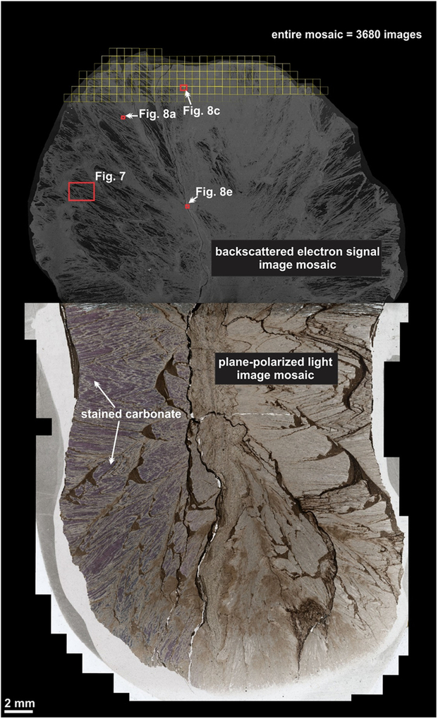
Fig. 6. Large-area image mosaic of the carbonate concretion showing the plane-polarized light image mosaic and the upper half from which a large-area Atlas 5 SEM (BSE) image mosaic was acquired.
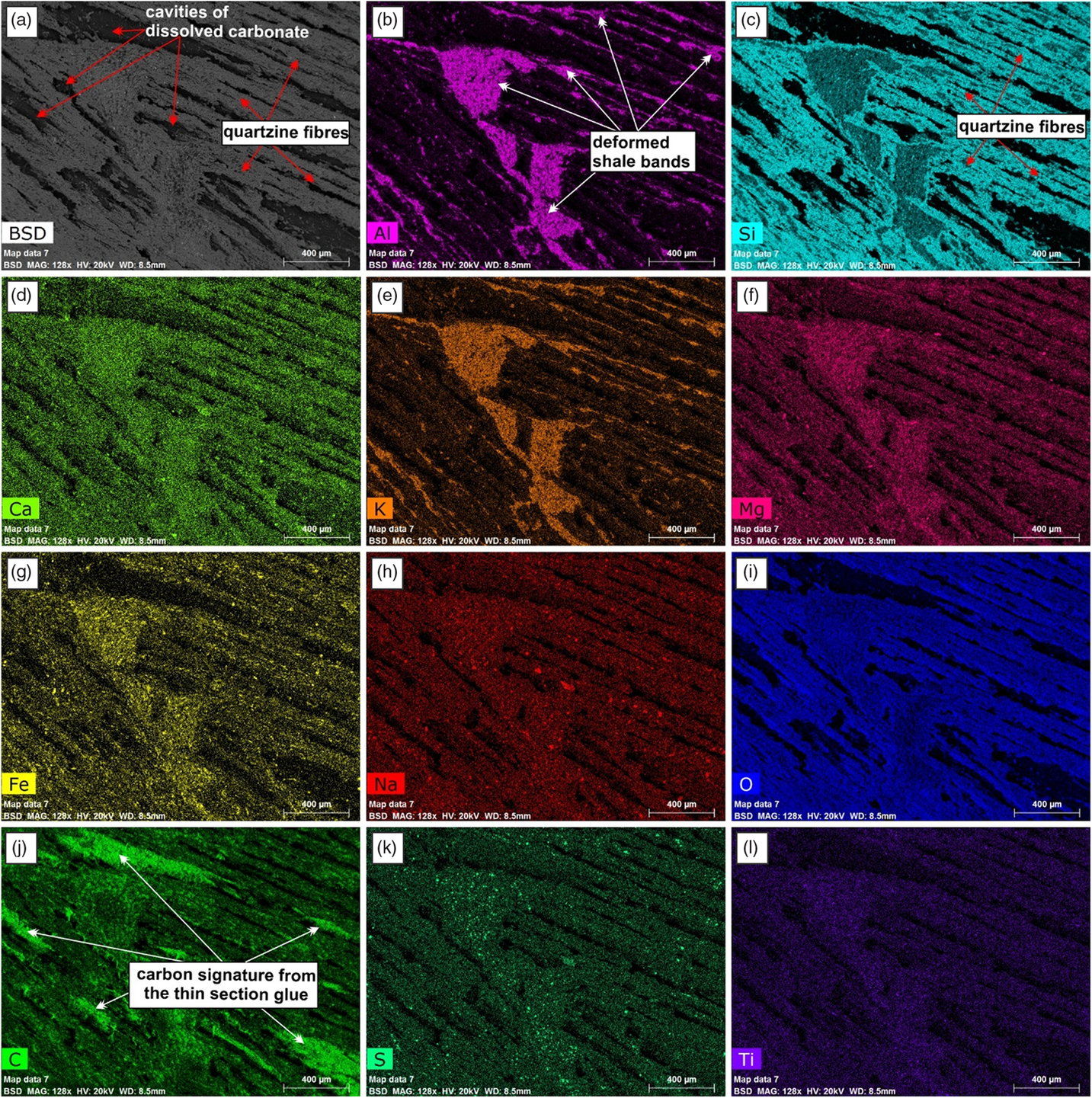
Fig. 7. Higher-magnification SEM-BSE images and EDS element maps of the part of the concretion from which the carbonate was removed showing the distribution of the quartz fibres and the deformed shale bands.
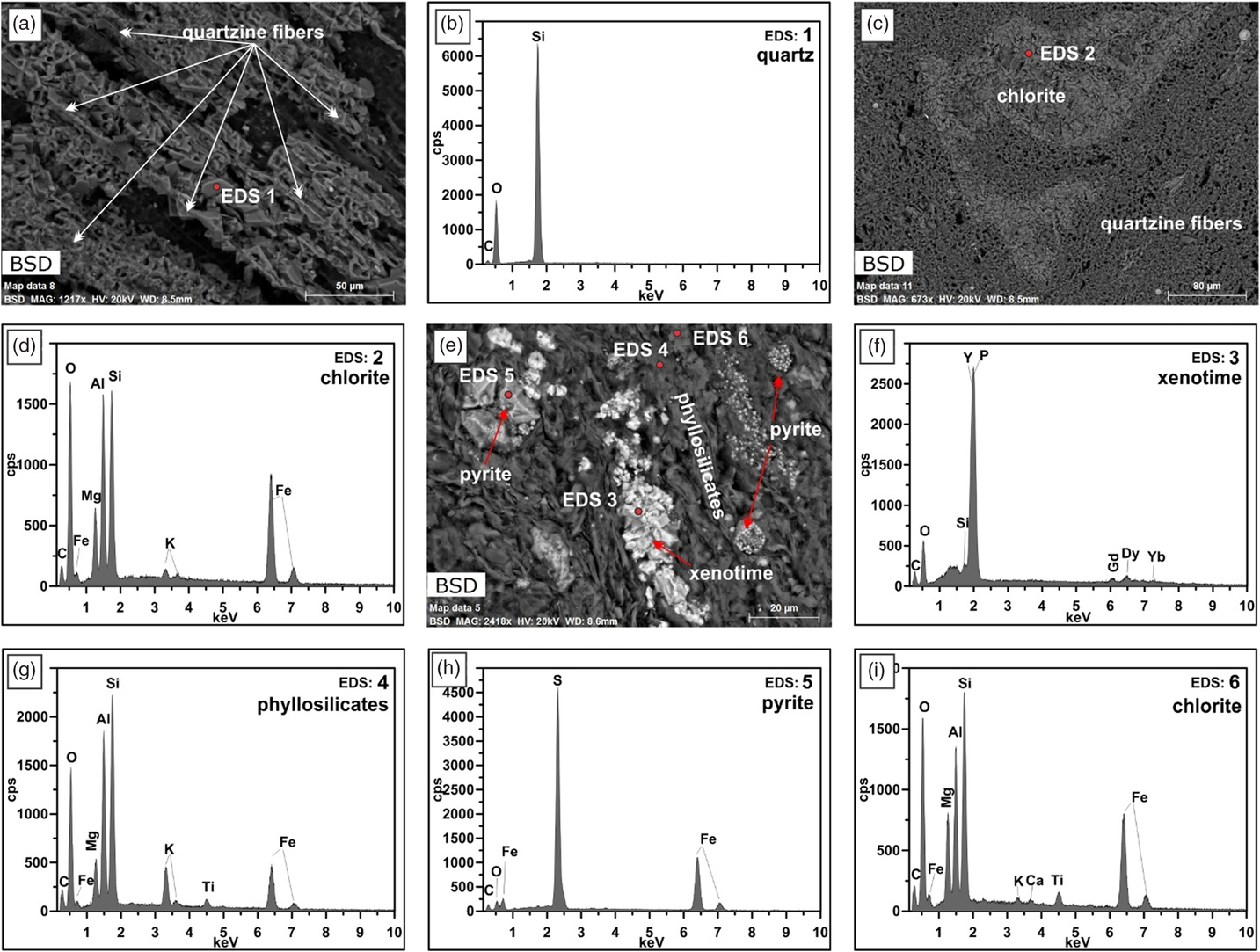
Fig. 8. Higher-magnification SEM-BSE images of the concretion. (a) Structure of the quartz fibres. (b) EDS point analyses of location 1 in (a). (c) Deformed part of a shale band consisting almost entirely of chlorite. (d) EDS point analyses of location 2 in (c). (e) Area in the shale that shows framboidal pyrite and xenotime. (f–i) EDS point analyses of locations 3 to 6 in (e).
The SEM image mosaic allowed for the investigation of an entire half of a large concretion. The internal structure could be investigated at higher resolution and the chemistry of the components could be determined. The PPL image mosaic of the entire thin-section shows the various components of the carbonate concretion (Fig. 6; Atlas 5 BBV dataset https://www.petapixelproject.com/mosaics/RH/CC-BBV/Carbonate-Concretion/index.html). The carbonate appears pink in the stained area of the thin-section. The deformed shale bands appear as a brown to dark brown colour. The area of the thin-section that had undergone acid treatment was imaged with the SEM (Fig. 6). The area that was occupied with carbonate before that treatment now appears as black empty voids within the network of quartz fibres and deformed shale bands (Fig. 6; Atlas 5 BBV dataset https://www.petapixelproject.com/mosaics/RH/CC-BBV/Carbonate-Concretion/index.html). These areas appear white in PPL since the light is transmitted through the underlying thin-section glass and remaining glue that holds the actual thin-section (see Atlas 5 BBV dataset https://www.petapixelproject.com/mosaics/RH/CC-BBV/Carbonate-Concretion/index.html).
The EDS element maps impressively show the distribution of the quartzine fibres and the deformed shale bands (Fig. 7; see also EDS maps in Atlas BBV dataset https://www.petapixelproject.com/mosaics/RH/CC-BBV/Carbonate-Concretion/index.html). A close investigation of the quartzine fibres reveals that they are formed of various shapes that look like casts of carbonate crystals and former cracks in the carbonate that were filled with quartzine, which were left behind after the carbonate was removed by etching with acid (Fig. 8a). The shale bands are composed of various types of phyllosilicates, chlorite, pyrite, quartz grains, titanium oxides, sodium feldspar, and in some cases xenotime (Fig. 8; see also linked EDS maps in the Atlas 5 BBV dataset https://www.petapixelproject.com/mosaics/RH/CC-BBV/Carbonate-Concretion/index.html). The carbonate to silica ratio in the spherules is c. 60:40; at the transition to the cone-in-cone structure, silica disappears.
Spherules in these carbonate concretions range in size from 0.5 mm to 12 mm in diameter. Spherules of larger size usually exhibit a perfect spherical shape (Fig. 5b), whereas medium- to small-sized spherules up to 3 mm in diameter are commonly tightly packed and may exhibit a shoebox shape as well as other irregular shapes (Fig. 9). The nuclei of the spherules are commonly very small and their identity cannot be deciphered. From the nuclei, numerous fine fibres of calcite and quartzine 2 to 6 μm in diameter radiate outwards. Under crossed nicols a characteristic black extinction cross is displayed by the spherules (Fig. 5). Within a given concretion, spherules in the same horizontal plane are usually of equal size. When adjoining spherules come into contact they share a compromise boundary (Fig. 9). Spherules with compromise boundaries depart in shape from the ideal spherical form. Spaces surrounding three or more spherules may be filled with patches of black shale that have been displaced into this space by the growth of the neighbouring spherules. In spherulitic concretions the total volume of black shale or silt is <20 %. At the contact between spherules and black shale a transition from spherule to cone-in-cone structure is commonly observed (Fig. 10). Where cone-in-cone structure follows the periphery of a spherule, the high concentration of quartzine fibres in the inner parts of the spherule is reduced and gives way to clear ferroan calcite (Fig. 11). Calcite in these cone-in-cone structures frequently exhibits distinctively curved twin lamellae and cleavages characteristic of fascicular optic and radiaxial mosaic (Kendall, Reference Kendall, Schneidermann and Harris1985; Fig. 12a). In some cases, the cone-in-cone structure appears shaped like a bottle brush (Fig. 12b). The foregoing observations document the intimate relationship between the spherulitic and cone-in-cone structures.
Fig. 9. Tightly packed spherules with compromise boundaries.
Fig. 10. Photomicrograph of cone-in-cone structure rimming spherules. The high concentration of quartzine fibres in the inner parts of the spherules is reduced and gives way to clear ferroan calcite in the rims of the spherules. Hand specimen 79072802-1. Horizontal width c. 36 mm.
Fig. 11. Close-up of cone-in-cone structure in the periphery of two spherules.
Fig. 12. (a) Calcite in cone-in-cone structure exhibiting distinctively curved twin lamellae and cleavages characteristic of fascicular optic and radiaxial mosaic (c.f. Kendall, Reference Kendall, Schneidermann and Harris1985). (b) Cone-in-cone structure shaped like a bottle brush.
In the present study, all of the examined cone-in-cone structures are made up of fine fibres of ferroan calcite. The smallest basic construction units in a cone-in-cone structure are slender conical tufts of fine fibres of calcite, which form various fan shapes with apical angles ranging from 15o to 70o (Figs 10, 11). The length of the fibrous tufts ranges from 0.5 to 15 mm. When three-dimensionally reconstructed, these slender conical tufts should be conical bundles of fine calcite fibres. The characteristic clay rings on cone-in-cone structures are the result of growth of fibrous tufts. As correctly interpreted by Franks (Reference Franks1969), the clay patches were pushed aside by the slender conical tufts until the clay patches butt against the sheaths of an earlier cone.
5. Carbon and oxygen stable isotopes
The carbon isotope values for the various types of concretions range from −28 ‰ to −7 ‰ (VPDB) (Fig. 13a); the oxygen values show a narrow spread between c. −17 ‰ and −9 ‰ (VPDB) with one runaway value of −29 ‰ (VPDB) (Fig. 13b).

Fig. 13. (a) Carbon and (b) oxygen isotope traverses across five different types of spherulitic and cone-in-cone concretions. XA – spherules grading downwards into cone-in-cone structure; XB – spherulitic concretion; XC – cone-in-cone structure on rim of spherulitic concretion; XD – micritic concretion with spherule rim; XE – cone-in-cone concretion.
6. Interpretation: mechanism of formation of spherules and cone-in-cone structures
Since the classic monograph of Bernauer (Reference Bernauer1929), who described experiments in which spherulitic growth was induced, a number of examples of successful experimental precipitation of fibrous spherules in the laboratory have been reported (Morse et al. Reference Morse, Warren and Donnay1932; Brooks et al. Reference Brooks, Clarke and Thurston1950; Heinisch, Reference Heinisch1970; Schwartz et al. Reference Selles-Martinez1971; McCauley & Roy, Reference McCauley and Roy1974). As initially suggested by Bernauer, most authors attribute the precipitation of spherules to two factors: the presence of impurities and one form or another of a gel as the medium of crystallization.
Based on modern concepts of crystal growth, Keith & Padden (Reference Keith and Padden1963) developed a phenomenological theory of spherulite crystallization from a viscous magma, emphasizing the role of impurities in the spherulite-forming melt. Once impurities are added to a melt, the rate of advance of a crystallization front no longer depends upon the diffusion of latent heat away from the growth site alone, but rather upon an interplay between the transport of heat and the diffusion of impurities. The growing crystal rejects the impurities preferentially, and the concentration of the impurity in the liquid adjacent to the crystal builds up to higher than the average value in the melt. If the melt is not disturbed, an impurity-rich layer of ‘thickness’ δ = D/G forms in the liquid at the interface with the growing crystal, where D is the diffusion coefficient for the impurity in the melt, and G the growth velocity of the crystal. When the ambient temperature of the impurity-rich layer is smaller than the equilibrium liquidus temperature, small projections can be formed at the interface without additional latent heat having to be transported away. The surface of the growing crystal becomes broken up into numerous hexagonal cells. In this cellular crystallization, impurities are collected in the grooves between the hexagonal cells.
In a spherulite-forming melt, D values are reduced by several orders of magnitude, as evidenced by high melt viscosity. Together with very low G values, small δ values result (in most cases <10−4 cm or <1 μm). Since the equilibrium liquidus temperature gradient in the impurity-rich layer is steep, the surface of a hypothetical growing sphere is rendered extremely unstable, and cellular crystallization is to be expected. In the spherule-forming system, cellulation advances to an extreme and fibres grow rapidly on the sites of the hexagonal cells while impurities fill the grooves. In other words, the properties of spherulite-forming melts are such that the surface of a hypothetical growing spherule is forced to develop long fibrous projections separated one from another by uncrystallized melt. Owing to the lower temperature gradient in the impurity-rich layer, the uncrystallized melt will solidify slowly through secondary crystallization to fill in the overall structure. In this theory, Keith & Padden (Reference Keith and Padden1963) showed that the growth of fibrous crystals in spherulite-forming melts is attributable to cellulation and fibrillation on a fine scale, and brought about by a diffusive segregation of impurities in the manner described above.
Thus far, no consideration has been given to the curvature of the spherical surface and divergence of the cellular fibres. For the hypothetical growing sphere to complete its development into a spherulitic habit, the fibrous crystals should possess the ability to branch non-crystallographically at a small angle. The former authors stated that it is a fundamental property of cellular crystallization in an impure melt that any perturbation of the surface profile on a growing crystal is stable and persistent only if its size is commensurate with δ. Small disordered regions or minute singularities of the growing crystal have an opportunity to act as sources of persistent new growths only if δ is very small. Impure melts having high viscosities meet this condition. As δ is decreased from a relatively large value in such a melt, there is at first little likelihood of non-crystallographic branches being developed. As δ decreases, there is an increasing probability that one of the larger singularities at the shoulder of a growing fibre is of sufficient size that, with further growth, it becomes a persistent surface feature. If this new growth has a crystallographic orientation departing slightly from that of the parent fibres, it gives rise ultimately to a new fibre, which diverges from the original. Thus, one initial fibre has split into two fibres, each about δ in width and each growing along the same preferred crystal axis but misaligned slightly with respect to the other. As δ decreases further, the probability of such an occurrence increases correspondingly and, when δ is very small, almost any island of surface disorder becomes a possible source of non-crystallographic branching. As far as branching is concerned, the essential difference between crystallization in simple liquids and in spherulite-forming melts is in the magnitude of δ. Only in spherulite-forming melts do sufficiently small diffusion coefficients exist to ensure values of δ that are small enough for branching to become predominantly non-crystallographic. Keith & Padden (Reference Keith and Padden1963) observed that in polymers where δ was relatively large, spherules with coarse fibres and open textures were formed. Although the phenomenological theory of spherulite crystallization was developed for melts, it should be applicable to precipitation from pore solutions in clastic sedimentary environments as it depends critically only on the numerical value of the δ parameter and the presence of two chemical species, where one represents an impurity that temporarily poisons the growing crystal surface.
The intimate association of quartzine and calcite in carbonate concretions from Île-aux-Grues/Île-aux-Oies at first sight seems hard to explain in terms of ordinary precipitation processes of these minerals. However, applying the phenomenological theory of Keith & Padden (Reference Keith and Padden1963), a convincing solution to the problem emerges.
Most spherules precipitated experimentally in the laboratory crystallized in a gelatinous medium in the presence of impurities. Silica gel is the most common medium used. The occurrence of silica gel has not been reported from clastic or biogenic siliceous pelagic deep-sea sediments (e.g. Hesse, Reference Hesse, McIlreath and Morrow1990a,b), not even in hydrothermally sourced ponds of mid-ocean ridges like the Atlantic II Deep in the Red Sea. However, experimental spherulite precipitation has also been achieved from alkaline aqueous solutions (e.g. Johnston et al. Reference Johnston, Merwin and Williamson1916). Alkaline conditions are established during early diagenesis in the lower sulfate-reduction zone (Hesse et al. Reference Hesse, Shah and Islam2004). If sufficient biogenic or detrital calcium carbonate has been dissolved in the oxidation zone, and the nitrate-reduction and upper sulfate-reduction zones where acidic conditions prevail, then fibrous calcium carbonate precipitation in the presence of impurities may start in the lower sulfate-reduction zone or the carbonate-reduction (methane generation) zone. The presence of ferroan calcite in the studied concretions speaks for the beginning of the precipitation in the carbonate-reduction zone, because in the sulfate-reduction zone Fe2+ is removed by sulfide and not available for incorporation into carbonate. The carbon isotope results (Fig. 13a) support an early diagenetic precipitation at the top of the methane-generating zone at a level where the effect of methane fractionation is still subordinate. (Note: C. Fong considers that precursor concretions formed at shallow subsurface depth, and their recrystallization leading to spherulitic and cone-in-cone structures occurred at depths in the order of 4 km after tectonic stacking.) No systematic variations between spherules (XB) and cone-in-cone structures (samples XC and XE) are recognizable. The oxygen isotope values would give temperatures too high even if a δ18O of Early Palaeozoic seawater of <−7 ‰ is assumed (Fig. 13b; cf. Hesse et al. Reference Hesse, Shah and Islam2004). However, low δ18O values may result from advection of pore waters from a greater subsurface depth (Hesse & Schacht, Reference Hesse, Schacht, Hünecke and Mulder2011).
Carbonate precipitation may occur alternating with silica precipitation, because carbonate crystallization lowers the pH (García-Ruiz et al. Reference García-Ruiz, Melero-Garcia and Hyde2009). Under alkaline conditions dissolved silica is present, depending on pH, either as orthosilicic acid (H4SiO4) or in its dissociated forms H3SiO4−1 (for pH >9) or H2SiO42 (for pH >13). Dissociation raises the silica solubility significantly (Hesse, Reference Hesse, McIlreath and Morrow1990a). Silica precipitation from supersaturated solutions involves polymerization in which monomeric acid first forms oligomers (dimers, tetramers, etc.) through the development of siloxane (Si–O–Si) bonds and then high-molecular-weight polymers (with molecular weights up to 10<2>000) which have colloidal dimensions (greater than 5 nm) and remain in suspension as sols unless precipitated as gels by metal hydroxides. The most commonly used hydroxide for silica precipitation in industrial applications is Mg(OH)2, also thought to be instrumental in the nucleation of opal-CT (Kastner et al. Reference Kastner, Keene and Gieskes1977). Presently known environments of inorganic silica precipitation are the playa lakes of the Coorong Lagoon, Australia, which have a pH of ~10, Lake Bogoria in the Kenya Rift Valley (Renaut et al. Reference Renaut, Tiercelin, Owen, Frostic, Renaut, Reid and Tiercelin1986; Renaut & Owen, Reference Renaut and Owen1988) and others. Here the silica probably goes through a gel stage. Precipitation takes place when the pH drops owing to decaying plant matter during evaporation. Conditions of the shallow lacustrine environment of the Coorong Lagoon would not have been applicable to the continental slope setting of Laurentia in Cambrian or Ordovician times.
However, as pointed out, pH-lowering through carbonate precipitation would have triggered silica precipitation. The presence of dissolved silica supplied by the dissolution of unstable biogenic opal-A (in Palaeozoic time provided by radiolarians and sponge spicules) during shallow burial leads to local supersaturation of silicic acid next to the growing carbonate crystals, initiating the adsorption and precipitation of silica on the positively charged carbonate crystal surfaces (Fig. 8a). Silica precipitation poisons carbonate crystal growth and causes bifurcation of the carbonate crystals. The chemical coupling of carbonate and silica precipitation enables continuous crystal splitting at non-crystallographic angles, thus producing the radiating spherulitic fibres. If the silica supersaturation in the pore water is low enough, direct precipitation of the silica as stable chalcedony or quartzine is possible instead of the metastable precursor opal-CT phase.
In the concretions described, the cement (represented by the crystallized spherules) to solid ratio is as high as 80:20. The type of sediment at the depth of concretion growth is a soupy mud with high water content (Müller, Reference Müller, Larsen and Chilingar1967). The presence of calcite nuclei dictates that calcite is the initial mineral precipitated, while silica, although in excessively high concentration, constitutes the impurity attributed to the crystallization of fibrous calcite. The silica that filled interfibre grooves underwent secondary crystallization and formed a fibrous network. In well-formed and fully developed spherules, these silica fibres dominate the entire network, consequently obscuring the manner of calcite branching of the calcite fibres. Could the silica have been introduced by replacement as in the case of silica replaced cone-in-cone structures reported by Lugli et al. (Reference Lugli, Reimold, Koeberl, Koeberl and Henkel2005)? This is next to impossible because of the fine fibrous intergrowth of ferroan calcite and silica in the spherules. The rimming cone-in-cone structure should then also have been replaced by silica.
Observation under the petrographic microscope reveals that transition from spherule to cone-in-cone structure is brought about by an increase in the angle of branching of the fibres. Since the transition is accompanied by the disappearance of silica fibres from the structure as confirmed by the SEM/EDS analyses, it appears that exhaustion of the silica reservoir is the cause of the change from spherulitic to cone-in-cone structure.
According to Lugli et al. (Reference Lugli, Reimold, Koeberl, Koeberl and Henkel2005), hypotheses concerning the formation of calcareous cone-in-cone structure belong to two groups: those assuming early displacive formation of concretions in soft, unconsolidated sediment, and those that emphasize late fracturing of concretions with or without excess pore fluid. In detail, the following hypotheses have been proposed (see also Mozley, Reference Mozley, Middleton, Church, Coniglio, Hardie and Longstaffe2003):
(1) Recrystallization of fibrous aragonite to calcite forming open cone fractures intruded by argillaceous matter (Tarr, Reference Tarr and Twenhofel1922; Gilman & Metzger, Reference Gilman and Metzger1967).
(2) Differential pressure solution on calcite fibres along conical shear planes induced by the weight of overlying strata (Tarr, Reference Usdowski1932).
(3) Settling and volume shrinkage during the slow dewatering of highly saturated and loosely packed subaerially exposed sediments (Shaub, Reference Shead1937).
(4) Precipitation of fibrous calcite along fractures or in concretionary masses. The fibres would then be deformed by ‘tractional forces’ during deformation of the host strata or during concretionary growth of the calcite component (Bonte et al. Reference Bonte, Denaeyer and Goguel1947).
(5) Crystallization of calcite fibres under gravity-induced differential stress, during gradual compaction of the sediment. The angles of cone apices would be determined by the plasticity of the enclosing sediment: large apical angles would indicate relatively low plasticity (Woodland, Reference Woodland1964).
(6) Early displacive growth of cone-shaped plumose aggregates of fibrous calcite (Franks, Reference Franks1969).
(7) Diagenetic water-escape structures promoting the ‘reordering of phyllitic elements within a sediment undergoing diagenetic compaction and which exhibits differences in porosity and competency in its lithological composition; cone-in-cone can be compared to a schistosity acquired in the realm of hydroplastic deformation’ (Becq-Giraudon, Reference Becq-Giraudon1990).
(8) Brittle fracturing of crystalline calcite aggregates, grown by a crack-seal mechanism in overpressured environments, and induced by a decrease in pore pressure of the plastic host sediment (Selles-Martinez, Reference Shaub1994).
(9) Shallow burial (<1500 m) precipitation from modified marine pore fluids (Hendry, Reference Hendry2002).
(10) Early diagenetic growth (depth <40 m), probably microbially mediated, in sandstone units beneath flooding surfaces and sequence boundaries (McBride et al. Reference McBride, Picard and Milliken2003).
7. Conclusions
The studied example of spherulitic carbonate concretions is only the fourth occurrence reported in the literature and the first example of an entire concretion documented by a large-area image mosaic dataset. The concretions occur in close association with cone-in-cone structure and show all transitions between end-member spherulitic concretions and cone-in-cone structure, with cone-in-cone forming towards the margins of individual spherules. Detailed petrographic analyses have shown that the spherules consist of an intergrowth of ferrous carbonate and quartzine fibres. The significance of the detection of the quartzine is that it is a key factor for the understanding of spherulitic growth. Silica in solution acts as an impurity that is the cause for spherulitic growth, as predicted by the theory of Keith & Padden (Reference Keith and Padden1963) that was developed for spherulitic crystallization from magmas and has been applied in this study for the first time to sedimentary deposits, i.e. the growth of spherulitic carbonate concretions. The transition from spherules to cone-in-cone occurs when the reservoir of dissolved silica that acted as an impurity is exhausted.
Author ORCIDs
Reinhard Hesse 0000-0002-6430-6186
Acknowledgements
We are grateful to Robert F. Martin and Jeanne Paquette for providing important references. Journal reviewer Kyungsik Choi and an anonymous reviewer are thanked for constructive criticism of the manuscript. The study was financially supported by grants from the Natural Sciences and Engineering Research Council of Canada (NSERC).


 Open access