INTRODUCTION
Manual muscle testing is an essential component of the complete neuromuscular exam. It allows for assessment of a patient’s isometric strength bilaterally and for systematic determination of motor deficits. From a neurological perspective, we generally seek to localize patterns of weakness to the upper motor neuron, lower motor neuron, nerve root, plexus, peripheral nerve, neuromuscular junction, or muscle, but what are we actually assessing to discern weakness? To address this question, we must consider the biomechanics of the musculoskeletal system. Biomechanical factors can greatly influence exam interpretations, and inform the rationale behind the classical teachings of how we should perform the exam. This article will first review the basic biomechanics of the musculoskeletal system relevant to manual muscle testing, highlighting factors contributing to strength assessment. Next, we discuss patient and examiner factors that can influence these biomechanics and interpretations of the exam. Finally, we recommend points to consider when performing manual muscle testing to ensure that confounding biomechanical factors do not interfere with neurological assessment.
BIOMECHANICS REVIEW
In biomechanical terms, manual muscle testing evaluates the patient’s ability to produce a moment-of-force (also known as “moment” or “torque”) about a given joint. While force is a linear descriptor (i.e. moves something in a straight line), a moment-of-force is an angular descriptor and can be thought of as the turning effect induced by a force, such as how a force applied by muscle can induce joint rotation. To create a moment-of-force, a force must be applied some distance away from the point about which motion is expected to occur. This is much like a teeter-totter, where sitting over the fulcrum causes no movement, but sitting on one of the ends does cause movement. In the human body, this occurs naturally as tendons are never inserted directly into a joint center but rather insert some distance adjacent to the joint center. It is our body’s natural development of leverage and while it occurs in all joints, it can be easily observed in a joint like the knee where the patella adds extra distance between the quadriceps tendon and knee joint axis of rotation to facilitate leverage. Correspondingly, the cross product of two variables contributes to a moment-of-force, as shown in equation (1):
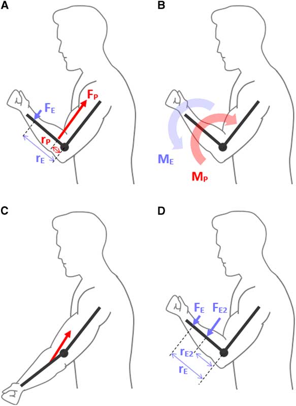
Here, M represents the moment-of-force about some point of rotation, F is the force applied, and r is the perpendicular distance between the applied force and point of rotation, termed the “moment arm.” In a human example, F might be the force in the biceps tendon; the moment arm, r might be the distance between the biceps tendon and the elbow joint; and M is the moment-of-force produced about the elbow (Figures 1A–1B). For more detail on moments-of-force and biomechanics in the musculoskeletal system, the reader is directed to the comprehensive text by Nigg and Herzog.Reference Nigg and Herzog
1
Figure 1 (A) A simplistic diagram is shown of a patient contracting their elbow flexors and producing a force (F
P) through the biceps tendon. Since the biceps tendon does not insert directly into the elbow joint, it can be seen that this force also does not act through the elbow joint center, and instead is separated by a perpendicular distance (r
P), also called the moment arm. Based on equation (1) in text (M=r×F), a moment-of-force (M
P) is produced which would have the tendency to flex the elbow, shown in B. Concurrently in A, another force is seen (F
E). This is the force applied by the examiner to the patient. Similarly, this force is applied a distance away from the elbow joint center, defined as the moment arm (r
E). Since this force is acting in the opposite direction, the moment produced by the examiner (M
E) serves to extend to elbow, or oppose the patient, as shown in B. To cause an isometric state, the moment of the examiner must be equal and opposite to that of the patient, and since the examiner applies force much further away from the elbow (i.e. a large moment arm), the amount of force required to resist the patient is much less than the force produced in the patient’s biceps tendon. (C) The patient is shown with an extended elbow and it can be seen that while the insertion point of the biceps tendon does not change, the muscle is drawn closer to the elbow joint center, causing smaller moment arms compared with the flexed position in (A). (D) It is shown, based on equation (1), that the force required by the examiner to produce an opposing moment decreases the further their point of force application (i.e. point where their resisting hand is placed) is from the elbow. The moment arm r
E2 likely represents the optimal point for estimating the patient’s strength in this example.
Thus, when the patient contracts their muscles, a moment-of-force is generated about the joint of interest. While this would normally cause joint movement, an examiner can perform an isometric assessment of strength by applying an equal and opposite moment-of-force to the patient (Figures 1A–1B). “Strength” is then determined for each joint based on how easily the examiner can resist motion or overcome the patient, and can be graded using the Medical Research Council system.
2
Of interest, while the exam is sometimes described in terms of muscle power, strength should be biomechanically distinguished from power in the context of manual muscle testing. Joint power is the product of the joint moment-of-force and the joint angular velocity; however, since manual muscle testing is isometric, the patient’s joint angular velocity should be zero, and so their power is zero too!
PATIENT FACTORS
Assuming the patient is neurologically intact, two factors must be considered with regards to the patient’s ability to produce a maximal moment-of-force, as seen in equation (1): (1) ability for muscle to produce maximum force and (2) maximizing muscle insertion moment arms.
First, with respect to muscle force, skeletal muscle sarcomeres can only produce maximum isometric force when actin and myosin filaments are fully overlapped, as described by neuromuscular physiologist and Nobel Laureate Sir Andrew Huxley (1917-2012) and colleagues in 1966.Reference Gordon, Huxley and Julien
3
This force-length relationship is also observed on a whole-muscle level, where a muscle can only achieve peak isometric force when it is at a length permitting maximum sarcomere overlap, which varies between individual muscles and patients. In general, uniarticular muscles tend to operate within a narrow range of fiber lengths while biarticular muscles tend to operate within a wider range, which of course can affect the muscle length at which maximal overlap is permitted.Reference Arnold and Delp
4
This becomes complicated when evaluating a specific joint movement, such as elbow flexion, as there can be both biarticular (biceps brachii) and uniarticular (brachialis, brachioradialis) muscles crossing the joint. Consequently, it becomes useful to consider muscle groups rather than individual muscles in terms of finding optimal muscle lengths in which the group as a whole can produce maximum force.
Second, with respect to moment arms, while muscle insertion points on bone clearly remain unchanged in an individual patient throughout a joint’s range of motion, moment arm lengths still vary by several centimeters depending on joint angle (shown in Figure 1C).Reference Rankin and Neptune
5
Interestingly, the joint angle at which moment arms might be at their maximum may not always be the same joint angle where muscle fibers are optimally oriented for maximum force production.Reference Hoy, Zajac and Gordon
6
Based on the above two points, the ability to produce maximum joint moments is dependent on optimization of muscle length (in terms of functionally synergistic groups) and muscle insertion moment arms, which is achieved by testing each muscle group at the appropriate joint angle. While no study has documented the ideal joint angle for producing maximal joint moments across all muscle groups evaluated in manual muscle testing, numerous biomechanical studies have been performed on isolated muscle groups.Reference Anderson, Madigan and Nussbaum
7
These studies demonstrate considerable fluctuation in the ideal joint angle depending on the joint and patient being tested, but since biomechanical studies often use research-grade isokinetic dynamometers for muscle testing that are rarely used or available in practice, the results may not be easily transferrable to manual muscle testing in clinical settings. However, in general, testing approximately mid-way through the joint range of motion will usually result in a reasonably large—though not necessarily maximal—joint moment capability. For smaller distal joints such as the metacarpophangeal joints (MCPs), it is often preferable to test the joint at full-range of motion, for example, testing MCP flexion strength with fingers fully extended.Reference Kamper, Fischer and Cruz
8
While a mid-flexed position is helpful for standardization and reproducibility, experienced examiners may take advantage of the fact that muscle strength may vary throughout the range of motion and use this to discern subtle weakness patterns.
Recognizing the above limitations, as long as the examiner uses a similar joint angle bilaterally and consistently across patients, a good approximation of the patient’s normal strength can still be made.
EXAMINER FACTORS
Since manual muscle testing relies on the examiner applying a moment-of-force against the patient to resist or overcome motion, force production and moment arms of the examiner must also be considered (Figures 1A–1B).
Force production by the examiner, as noted in the classic text by Kendall, is best applied gradually and directly opposite the line of pull of the segment being tested, allowing the subject to “get set and hold,” with uniform application of force preferred to minimize discomfort.Reference Kendall, McCreary, Provance, Rodgers and Romani
9
While manual muscle testing is sometimes described as a test comparing the examiner’s strength to the patient’s strength, this is not strictly correct. For example, assume an examiner is testing elbow flexion in a patient. The examiner stabilizes the patient’s elbow with one hand, and pulls on the patient’s wrist with their other hand as the patient attempts to flex. Here, the patient’s biceps brachii and brachialis have been isolated, but tested against the examiner whose muscles have not been isolated and may include contributions from the biceps and brachialis, but also muscles of the chest or back depending on positioning. This discrepancy between muscles used by the patient and examiner is more prominent when examining the lower extremity as the examiner will continue to utilize their upper extremity for resistance. The effect may be amplified in elderly patients, whose normal strength is naturally lower than younger patients. Overall, discrepancy between muscles used by the patient and examiner is not a concern for conducting manual muscle testing as long as the examiner is aware of this fact and considers it when forming an evaluation of the patient’s relative strength.
With regards to moment arms, hand positioning can afford significant mechanical advantage to the examiner. From equation (1), it can be seen that the examiner is required to use less force to produce an opposing moment the further their grip is placed from the joint being evaluated. Thus, to achieve a good estimation of the force required to resist or overcome the patient, it is recommended that the examiner place their hands approximately mid-way on the distal segment of the patient for simplicity and reproducibility (Figure 1D), at least initially. For instance, when assessing elbow flexor strength, an ideal initial position for the examiner to place their hand for resistance would be mid-way on the patient’s forearm. Again, using similar positioning bilaterally and across patients to facilitate consistent strength assessments is important. Moment arms may also be used to the examiner’s advantage to discern mild weakness in patients. For example, by shifting their hand placement distally, the examiner can generate a greater moment arm using the same force to elicit mild weakness. Similarly, in more athletic patients with high muscle mass whom the examiner may struggle to resist with mid-point, mid-range-of-motion testing, the examiner could either shift hand placement distally or test the muscle at a more disadvantageous position for the patient (e.g. triceps in full elbow flexion). Clinical experience may allow the examiner more freedom to use different moment arms at different joints without compromising exam sensitivity.
These points highlight that manual muscle testing is not a direct comparison of strength between the patient and examiner. Thus, it is important that the patient’s ability to resist being overcome is not used as the standard for “normal.” Instead, the MRC criteria simply define 5/5 strength as “normal,” which is a subjective assessment by the examiner based on their own experience and expectation for normal.
2
CLINICAL FACTORS
While the above discussion has focused on manual muscle testing in the neuromuscular exam from a strictly biomechanical perspective, there are other clinical factors that could also indirectly impact biomechanics and the overall exam. At the forefront, examiner experience is critical. For instance, neurology clinical skills are unsurprisingly lower among medical students and junior residents compared to senior residents and faculty, potentially relating to inconsistent technique and reduced clinical exposure to establish strength norms.Reference Kendall, McCreary, Provance, Rodgers and Romani
9
In addition, the discussion above also assumes maximal effort by the patient, which may be compromised by level of attention (e.g. in delirium) or effort, or pain-related limitations. Again, clinical experience is necessary to identify these features, but a clue may be inconsistent strength measurements. Importantly, the examiner should also consider the suspected clinical localization(s) of the patient’s symptoms: for instance, the initial isometric strength test might be quite representative of weakness localized to the lower motor neuron, whereas repeated testing is needed to reveal fatigable weakness in neuromuscular junction disorders. Isometric strength assessment in patients with spasticity from upper motor neuron dysfunction can fail to show poor functional performance that is best seen with voluntary movement.
CONCLUSION
This technical discussion on biomechanics is clinically relevant to the neuromuscular exam because a lack of consideration for biomechanics can lead to an incorrect interpretation of the patient’s true maximal strength. Whilst these errors may be subtle in a patient whose neurological or musculoskeletal system is intact, they may be highly consequential in patients with deficits. To mitigate these errors, good physical examination skills are critical, as highlighted in the “key points” Box 1.
Box 1 Key points for manual muscle testing


INTRODUCTION
Manual muscle testing is an essential component of the complete neuromuscular exam. It allows for assessment of a patient’s isometric strength bilaterally and for systematic determination of motor deficits. From a neurological perspective, we generally seek to localize patterns of weakness to the upper motor neuron, lower motor neuron, nerve root, plexus, peripheral nerve, neuromuscular junction, or muscle, but what are we actually assessing to discern weakness? To address this question, we must consider the biomechanics of the musculoskeletal system. Biomechanical factors can greatly influence exam interpretations, and inform the rationale behind the classical teachings of how we should perform the exam. This article will first review the basic biomechanics of the musculoskeletal system relevant to manual muscle testing, highlighting factors contributing to strength assessment. Next, we discuss patient and examiner factors that can influence these biomechanics and interpretations of the exam. Finally, we recommend points to consider when performing manual muscle testing to ensure that confounding biomechanical factors do not interfere with neurological assessment.
BIOMECHANICS REVIEW
In biomechanical terms, manual muscle testing evaluates the patient’s ability to produce a moment-of-force (also known as “moment” or “torque”) about a given joint. While force is a linear descriptor (i.e. moves something in a straight line), a moment-of-force is an angular descriptor and can be thought of as the turning effect induced by a force, such as how a force applied by muscle can induce joint rotation. To create a moment-of-force, a force must be applied some distance away from the point about which motion is expected to occur. This is much like a teeter-totter, where sitting over the fulcrum causes no movement, but sitting on one of the ends does cause movement. In the human body, this occurs naturally as tendons are never inserted directly into a joint center but rather insert some distance adjacent to the joint center. It is our body’s natural development of leverage and while it occurs in all joints, it can be easily observed in a joint like the knee where the patella adds extra distance between the quadriceps tendon and knee joint axis of rotation to facilitate leverage. Correspondingly, the cross product of two variables contributes to a moment-of-force, as shown in equation (1):
Here, M represents the moment-of-force about some point of rotation, F is the force applied, and r is the perpendicular distance between the applied force and point of rotation, termed the “moment arm.” In a human example, F might be the force in the biceps tendon; the moment arm, r might be the distance between the biceps tendon and the elbow joint; and M is the moment-of-force produced about the elbow (Figures 1A–1B). For more detail on moments-of-force and biomechanics in the musculoskeletal system, the reader is directed to the comprehensive text by Nigg and Herzog.Reference Nigg and Herzog 1
Figure 1 (A) A simplistic diagram is shown of a patient contracting their elbow flexors and producing a force (F P) through the biceps tendon. Since the biceps tendon does not insert directly into the elbow joint, it can be seen that this force also does not act through the elbow joint center, and instead is separated by a perpendicular distance (r P), also called the moment arm. Based on equation (1) in text (M=r×F), a moment-of-force (M P) is produced which would have the tendency to flex the elbow, shown in B. Concurrently in A, another force is seen (F E). This is the force applied by the examiner to the patient. Similarly, this force is applied a distance away from the elbow joint center, defined as the moment arm (r E). Since this force is acting in the opposite direction, the moment produced by the examiner (M E) serves to extend to elbow, or oppose the patient, as shown in B. To cause an isometric state, the moment of the examiner must be equal and opposite to that of the patient, and since the examiner applies force much further away from the elbow (i.e. a large moment arm), the amount of force required to resist the patient is much less than the force produced in the patient’s biceps tendon. (C) The patient is shown with an extended elbow and it can be seen that while the insertion point of the biceps tendon does not change, the muscle is drawn closer to the elbow joint center, causing smaller moment arms compared with the flexed position in (A). (D) It is shown, based on equation (1), that the force required by the examiner to produce an opposing moment decreases the further their point of force application (i.e. point where their resisting hand is placed) is from the elbow. The moment arm r E2 likely represents the optimal point for estimating the patient’s strength in this example.
Thus, when the patient contracts their muscles, a moment-of-force is generated about the joint of interest. While this would normally cause joint movement, an examiner can perform an isometric assessment of strength by applying an equal and opposite moment-of-force to the patient (Figures 1A–1B). “Strength” is then determined for each joint based on how easily the examiner can resist motion or overcome the patient, and can be graded using the Medical Research Council system. 2
Of interest, while the exam is sometimes described in terms of muscle power, strength should be biomechanically distinguished from power in the context of manual muscle testing. Joint power is the product of the joint moment-of-force and the joint angular velocity; however, since manual muscle testing is isometric, the patient’s joint angular velocity should be zero, and so their power is zero too!
PATIENT FACTORS
Assuming the patient is neurologically intact, two factors must be considered with regards to the patient’s ability to produce a maximal moment-of-force, as seen in equation (1): (1) ability for muscle to produce maximum force and (2) maximizing muscle insertion moment arms.
First, with respect to muscle force, skeletal muscle sarcomeres can only produce maximum isometric force when actin and myosin filaments are fully overlapped, as described by neuromuscular physiologist and Nobel Laureate Sir Andrew Huxley (1917-2012) and colleagues in 1966.Reference Gordon, Huxley and Julien 3 This force-length relationship is also observed on a whole-muscle level, where a muscle can only achieve peak isometric force when it is at a length permitting maximum sarcomere overlap, which varies between individual muscles and patients. In general, uniarticular muscles tend to operate within a narrow range of fiber lengths while biarticular muscles tend to operate within a wider range, which of course can affect the muscle length at which maximal overlap is permitted.Reference Arnold and Delp 4 This becomes complicated when evaluating a specific joint movement, such as elbow flexion, as there can be both biarticular (biceps brachii) and uniarticular (brachialis, brachioradialis) muscles crossing the joint. Consequently, it becomes useful to consider muscle groups rather than individual muscles in terms of finding optimal muscle lengths in which the group as a whole can produce maximum force.
Second, with respect to moment arms, while muscle insertion points on bone clearly remain unchanged in an individual patient throughout a joint’s range of motion, moment arm lengths still vary by several centimeters depending on joint angle (shown in Figure 1C).Reference Rankin and Neptune 5 Interestingly, the joint angle at which moment arms might be at their maximum may not always be the same joint angle where muscle fibers are optimally oriented for maximum force production.Reference Hoy, Zajac and Gordon 6
Based on the above two points, the ability to produce maximum joint moments is dependent on optimization of muscle length (in terms of functionally synergistic groups) and muscle insertion moment arms, which is achieved by testing each muscle group at the appropriate joint angle. While no study has documented the ideal joint angle for producing maximal joint moments across all muscle groups evaluated in manual muscle testing, numerous biomechanical studies have been performed on isolated muscle groups.Reference Anderson, Madigan and Nussbaum 7 These studies demonstrate considerable fluctuation in the ideal joint angle depending on the joint and patient being tested, but since biomechanical studies often use research-grade isokinetic dynamometers for muscle testing that are rarely used or available in practice, the results may not be easily transferrable to manual muscle testing in clinical settings. However, in general, testing approximately mid-way through the joint range of motion will usually result in a reasonably large—though not necessarily maximal—joint moment capability. For smaller distal joints such as the metacarpophangeal joints (MCPs), it is often preferable to test the joint at full-range of motion, for example, testing MCP flexion strength with fingers fully extended.Reference Kamper, Fischer and Cruz 8 While a mid-flexed position is helpful for standardization and reproducibility, experienced examiners may take advantage of the fact that muscle strength may vary throughout the range of motion and use this to discern subtle weakness patterns.
Recognizing the above limitations, as long as the examiner uses a similar joint angle bilaterally and consistently across patients, a good approximation of the patient’s normal strength can still be made.
EXAMINER FACTORS
Since manual muscle testing relies on the examiner applying a moment-of-force against the patient to resist or overcome motion, force production and moment arms of the examiner must also be considered (Figures 1A–1B).
Force production by the examiner, as noted in the classic text by Kendall, is best applied gradually and directly opposite the line of pull of the segment being tested, allowing the subject to “get set and hold,” with uniform application of force preferred to minimize discomfort.Reference Kendall, McCreary, Provance, Rodgers and Romani 9 While manual muscle testing is sometimes described as a test comparing the examiner’s strength to the patient’s strength, this is not strictly correct. For example, assume an examiner is testing elbow flexion in a patient. The examiner stabilizes the patient’s elbow with one hand, and pulls on the patient’s wrist with their other hand as the patient attempts to flex. Here, the patient’s biceps brachii and brachialis have been isolated, but tested against the examiner whose muscles have not been isolated and may include contributions from the biceps and brachialis, but also muscles of the chest or back depending on positioning. This discrepancy between muscles used by the patient and examiner is more prominent when examining the lower extremity as the examiner will continue to utilize their upper extremity for resistance. The effect may be amplified in elderly patients, whose normal strength is naturally lower than younger patients. Overall, discrepancy between muscles used by the patient and examiner is not a concern for conducting manual muscle testing as long as the examiner is aware of this fact and considers it when forming an evaluation of the patient’s relative strength.
With regards to moment arms, hand positioning can afford significant mechanical advantage to the examiner. From equation (1), it can be seen that the examiner is required to use less force to produce an opposing moment the further their grip is placed from the joint being evaluated. Thus, to achieve a good estimation of the force required to resist or overcome the patient, it is recommended that the examiner place their hands approximately mid-way on the distal segment of the patient for simplicity and reproducibility (Figure 1D), at least initially. For instance, when assessing elbow flexor strength, an ideal initial position for the examiner to place their hand for resistance would be mid-way on the patient’s forearm. Again, using similar positioning bilaterally and across patients to facilitate consistent strength assessments is important. Moment arms may also be used to the examiner’s advantage to discern mild weakness in patients. For example, by shifting their hand placement distally, the examiner can generate a greater moment arm using the same force to elicit mild weakness. Similarly, in more athletic patients with high muscle mass whom the examiner may struggle to resist with mid-point, mid-range-of-motion testing, the examiner could either shift hand placement distally or test the muscle at a more disadvantageous position for the patient (e.g. triceps in full elbow flexion). Clinical experience may allow the examiner more freedom to use different moment arms at different joints without compromising exam sensitivity.
These points highlight that manual muscle testing is not a direct comparison of strength between the patient and examiner. Thus, it is important that the patient’s ability to resist being overcome is not used as the standard for “normal.” Instead, the MRC criteria simply define 5/5 strength as “normal,” which is a subjective assessment by the examiner based on their own experience and expectation for normal. 2
CLINICAL FACTORS
While the above discussion has focused on manual muscle testing in the neuromuscular exam from a strictly biomechanical perspective, there are other clinical factors that could also indirectly impact biomechanics and the overall exam. At the forefront, examiner experience is critical. For instance, neurology clinical skills are unsurprisingly lower among medical students and junior residents compared to senior residents and faculty, potentially relating to inconsistent technique and reduced clinical exposure to establish strength norms.Reference Kendall, McCreary, Provance, Rodgers and Romani 9 In addition, the discussion above also assumes maximal effort by the patient, which may be compromised by level of attention (e.g. in delirium) or effort, or pain-related limitations. Again, clinical experience is necessary to identify these features, but a clue may be inconsistent strength measurements. Importantly, the examiner should also consider the suspected clinical localization(s) of the patient’s symptoms: for instance, the initial isometric strength test might be quite representative of weakness localized to the lower motor neuron, whereas repeated testing is needed to reveal fatigable weakness in neuromuscular junction disorders. Isometric strength assessment in patients with spasticity from upper motor neuron dysfunction can fail to show poor functional performance that is best seen with voluntary movement.
CONCLUSION
This technical discussion on biomechanics is clinically relevant to the neuromuscular exam because a lack of consideration for biomechanics can lead to an incorrect interpretation of the patient’s true maximal strength. Whilst these errors may be subtle in a patient whose neurological or musculoskeletal system is intact, they may be highly consequential in patients with deficits. To mitigate these errors, good physical examination skills are critical, as highlighted in the “key points” Box 1.
Box 1 Key points for manual muscle testing
Disclosures
RTL and MMCY do not have any disclosures. AG reports personal fees from Adkins Research Group, personal fees from MD Analytics/MedePanel, other from AHA Health Ltd, other from SnapDx, outside the submitted work.
Statement of Authorship
RTL conceived of the work and developed the idea with AG and MMCY. RTL drafted the article and figures and AG and MMCY revised it critically. All authors approved the final version of the manuscript and are accountable for all aspects of the work.