


Nomenclature
- ESA
-
European Space Agency
- JUICE
-
Jupiter Icy Moons Explorer
- EDS
-
Earth Departure Stage
- GTO
-
geostationary transfer orbit
- ESPRIT
-
European System Providing Refueling, Infrastructure and Telecommunications
- KBO
-
Kuiper Belt object
- NAC
-
narrow-angle camera
- WAC
-
wide-angle camera
- SEIS
-
Seismic Experiment for Interior Structure
- SAM
-
Sample Analysis at Mars
- TRL
-
technology readiness level
- NTO
-
nitrogen tetroxide
- MMH
-
monomethylhydrazine
- MON
-
mixed oxides of nitrogen
- RTGs
-
radioisotope thermoelectric generators
- LNCAO
-
lithiated nickel cobalt aluminumoxide
- TRN
-
terrain-relative navigation
- SLAM
-
simultaneous localisation and mapping
- JWST
-
James Webb Space Telescope
- GIS
-
graphical information system
- RC
-
Ritchey-Cherétien
- FP
-
focal plane
1.0 Introduction
Proposals for missions to the outer Solar System are plentiful and detailed [Reference Deutsch, Panicucci, Tenelanda-Osorio, Da Poian, Cho and Venigalla1, Reference Barnes, Turtle, Trainer, Lorenz, MacKenzie, Brinckerhoff and Cable2], with a strong science case for a return to this region. Receiving particular focus and as yet remaining without a confirmed mission, the ice giants of Uranus and Neptune present intriguing targets for future Solar System exploration. Since Voyager 2’s brief encounter with Neptune and its moon Triton in 1989, advancements in planetary science instrumentation have been deployed to various other celestial bodies in the Solar System, revealing the potential benefits of a return to the Neptunian system [Reference Alibay, Fernandes, McGranaghan, Leonard, Clegg, Craig and Day3]. Voyager 2’s key findings include the discovery of Neptune’s Great Dark Spot, a massive anticyclonic storm, and the detection of a dynamic atmosphere with the fastest recorded winds in the Solar System. For Triton, the mission revealed a thin nitrogen atmosphere, the presence of geysers and diverse terrain indicative of an active geologic past. Despite these discoveries, several outstanding questions remain, such as the driving forces behind Neptune’s extreme atmospheric dynamics and the nature of Triton’s potential subsurface ocean, geologic activity and atmospheric processes [Reference Masters, Achilleos, Agnor, Campagnola, Charnoz, Christophe and Coates4].
Reviews of the future mission landscape from the United States, in the form of the last planetary science decadal survey (2013–2022), stated that a Neptune system orbiter and probe would be of high scientific interest with further studies required in areas such as astrodynamics, suitable power and propulsion, communications, thermal protection and aerocapture were needed. Furthermore, a flyby is advised against given the small cost-saving relative to the decreased science return. Since then, a number of proposals have addressed these concerns [e.g. Ref. Reference Alibay, Fernandes, McGranaghan, Leonard, Clegg, Craig and Day5], and more recently, the Voyage 2050 recommendations to the ESA on the European side suggested a future L-class mission is allocated to the exploration of the moons of the giant planets, including Uranus and Neptune. Noted is the agency’s heritage with the success of the Cassini-Huygens mission, which undertook such a task with the Saturnian system, and the recently launched Jupiter Icy Moons Explorer (JUICE), which will explore the moons of Jupiter. A possible dual-spacecraft in a mother-daughter configuration with an additional in-situ element to characterise surface and sub-surface environments is suggested.
The Arcanum mission (Fig. 1), consisting of such a spacecraft, is currently under study by Conex Research, a research organisation specialising in near-future space mission design concepts, and is designed for operation in the Neptunian system. This planet was selected as it offers access to not only the fastest winds and the most distant planetary conditions in the Solar System, but also as it allows repeated orbital flybys and extensive observations of one of the most interesting bodies in the Solar System, Triton. It is strongly believed that Triton was at some point captured by Neptune and originally formed much further away from the Sun than where it currently resides. Furthermore, the limited observations available show signs of activity on its surface, leading to speculation of internal heat and even a potential internal ocean [Reference Masters, Achilleos, Agnor, Campagnola, Charnoz, Christophe and Coates4]. Aiming to address some areas of concern noted in the decadal survey surrounding a low science yield for a high cost and in light of these new Voyage 2050 recommendations to ESA, this paper focuses on advances in the study of potential transfers to Neptune and a detailed description of an updated Triton landing system [Reference McKevitt, Bornberg, Dixon, Ayin-Walsh, Parkinson-Swift, Morgan, Beegadhur, Criscola, Heinreichsberger, Simha Reddy Pappula, Bulla, Patel, Laad, Forder, Singh, Moor, Foghis, Wedde, McDougall, Kent and Raj6, Reference McKevitt, Bulla, Dixon, Criscola, Parkinson-Swift, Bornberg, Singh, Patel, Laad, Forder, Ayin-Walsh, Beegadhur, Wedde, Pappula, McDougall, Foghis, Kent, Morgan, Raj and Heinreichsberger7], particularly the addition of a new manoeuvring unit, Tenzing. The spacecraft configuration for the mission can be seen in Fig. 2 and, simply, consists of the primary Neptune orbiter Somerville and the Tenzing orbital manoeuvring unit. Mated to the latter for subsequent detachment once in orbit around Triton are the Bingham soft lander and three surface impact penetrators. Figure 3 shows the spatial layout of the mission components which will be delivered to Neptune: Tenzing, with the attached surface impact penetrators, Bingham, and the Somerville orbiter. Additionally, Fig. 4 shows the spatial layout of the Tenzing orbital manoeuvring unit. To deliver Arcanum onto a deep space trajectory to Neptune, an Earth Departure Stage (EDS) provides propulsion, attitude control, and other critical support.

Figure 1. An artistic illustration of the Arcanum mission in orbit around Neptune before Triton lander deployment.

Figure 2. Configuration of the Arcanum space segment.
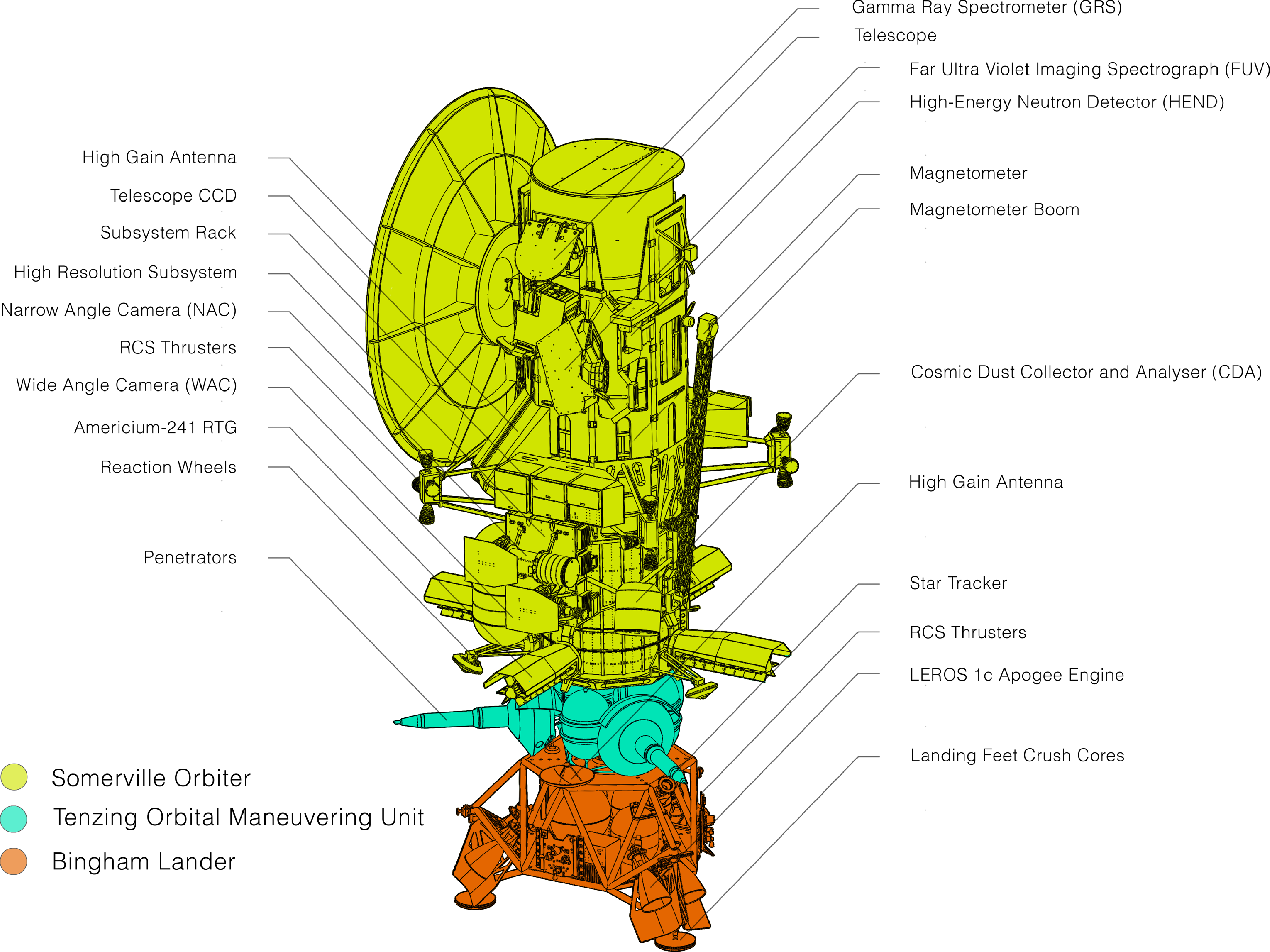
Figure 3. Configuration of the Arcanum spacecraft.
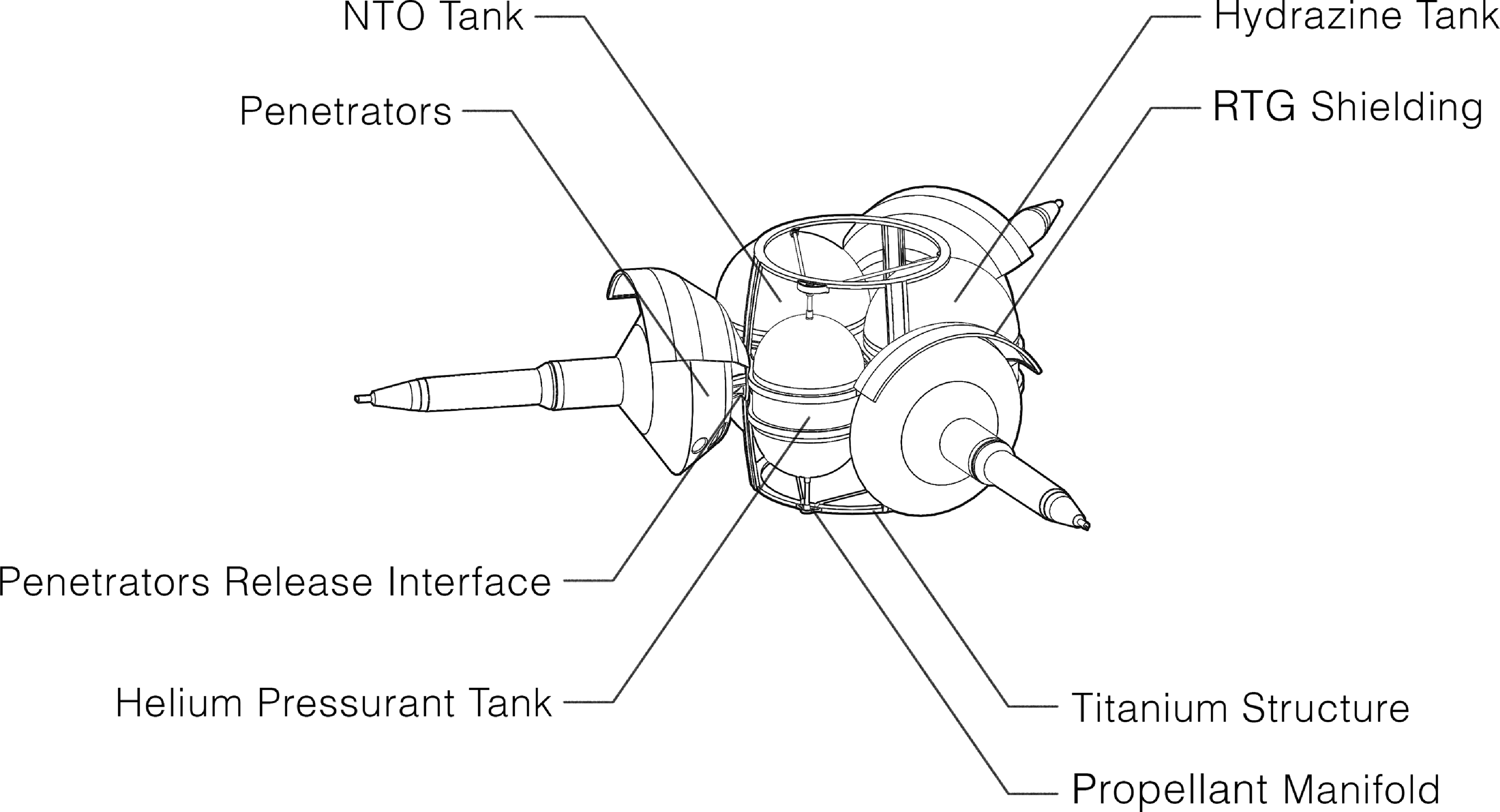
Figure 4. Configuration of the Tenzing orbital manoeuvring unit.
This study takes into consideration the new upper mass limit which can be expected with the next generation of launch vehicle – that being an order of magnitude increase from Falcon Heavy’s 16 tonnes to geostationary transfer orbit (GTO) to starship’s estimated approximately 100 tonnes to GTO [8, 9] – and aims to highlight the advantages to space science these advances will deliver.
2.0 Launch and mass constraints
When considering the timescales referenced in this proposal, a certain degree of extrapolation is needed to understand the top-end lifting capabilities missions will benefit from in the coming decades. Such analysis of the soon-to-be operational super heavy-lift launch vehicles has been carried out in this study and detailed in previous publications [Reference McKevitt, Bornberg, Dixon, Ayin-Walsh, Parkinson-Swift, Morgan, Beegadhur, Criscola, Heinreichsberger, Simha Reddy Pappula, Bulla, Patel, Laad, Forder, Singh, Moor, Foghis, Wedde, McDougall, Kent and Raj6, Reference McKevitt, Bulla, Dixon, Criscola, Parkinson-Swift, Bornberg, Singh, Patel, Laad, Forder, Ayin-Walsh, Beegadhur, Wedde, Pappula, McDougall, Foghis, Kent, Morgan, Raj and Heinreichsberger7]. However, simply understanding the launchers’ available is not sufficient. On-orbit and perhaps even cislunar – that being between the Earth and the Moon – refuelling, tugging and servicing infrastructure can be expected to further raise the upper-level surface to GTO payload mass, and references to such infrastructure by companies such as SpaceX and accompanying funding by NASA are encouraging signs this infrastructure could be relied upon in future [Reference Skelly10]. In fact, the current NASA-funded Artemis concept of operations includes a number of such refuelling missions [Reference Witt and Rowe11].
Considering on-orbit infrastructure, a reliable reference point with significant documentation can be taken to be the Lunar Gateway [12]. A refuelling module launching in 2027, specifically the European System Providing Refueling, Infrastructure and Telecommunications (ESPRIT), has been approved and a contractor appointed, limited for the moment to ion engine support. While this infrastructure will enable planned dynamic lunar operations, it does not yet promise to provide the support to make the Gateway a staging post for deep-space missions, an underpinning feature of the station during its proposal.
Contemplating instead refuelling operations supported from Earth, NASA-funded studies undertaken by SpaceX [Reference Skelly10] will ensure the planned starship-starship refuels can take place, calculated to increase the vehicle’s mass to GTO to 100 tonnes. This is a great increase when compared to the 21 tonnes to GTO possible with a single launch [9].
The Arcanum mission, while designed to highlight the science potential of these increased launch masses, has sought to not only consider mass limits which may be technically motivated, but which are also politically and financially palatable. To this end, a spacecraft mass to GTO possible with one launch – that being the aforementioned 21 tonnes – has been the goal, with possible expansion to a launch and single refuel.
In attempts to mitigate against an over-weight payload, a number of solutions were investigated in previous work [Reference McKevitt, Bornberg, Dixon, Ayin-Walsh, Parkinson-Swift, Morgan, Beegadhur, Criscola, Heinreichsberger, Simha Reddy Pappula, Bulla, Patel, Laad, Forder, Singh, Moor, Foghis, Wedde, McDougall, Kent and Raj6, Reference McKevitt, Bulla, Dixon, Criscola, Parkinson-Swift, Bornberg, Singh, Patel, Laad, Forder, Ayin-Walsh, Beegadhur, Wedde, Pappula, McDougall, Foghis, Kent, Morgan, Raj and Heinreichsberger7]:
-
Altering the propulsion system or propellant combination in the EDS [Reference McKevitt, Bornberg, Dixon, Ayin-Walsh, Parkinson-Swift, Morgan, Beegadhur, Criscola, Heinreichsberger, Simha Reddy Pappula, Bulla, Patel, Laad, Forder, Singh, Moor, Foghis, Wedde, McDougall, Kent and Raj6]
-
Aerobraking at Neptune to reduce the fuel mass needed for capture
-
Launching the EDS separately and docking in orbit
However, it was determined that a single refuel was both sufficient and favourable given the low cost, low operational risk and simplicity of implementation. This ease of expansion of starship’s payload capacity is a perfect demonstration of the significance of its introduction to the launcher market, and it was therefore selected as the Arcanum launch vehicle.
3.0 Transfer to neptune
3.1 Radiation implications
The spacecraft will experience a number of radiation challenges in deep space, shielding against which provides targeted coverage of sensitive instruments and components. The particularly intense environment around Jupiter will be the strongest experienced by the mission during a 5-hour gravity assist flyby, where particles with energies of approximately 100 GeV, 50 the energy of those at Earth, are concentrated [Reference Roussos, Allanson, André, Bertucci, Branduardi-Raymont, Clark and Dialynas13]. This acts as a design point for the mitigating multi-layer insulating materials of aluminised Mylar, Kapton, Dacron mesh and indium tin oxide, which will be required by the mission. While this presents a difficult challenge to the spacecraft design, it also offers an opportunity for science as communications equipment can be repurposed to allow the further mapping of this radiation environment, something useful for future passing spacecraft.
3.2 Astrodynamics
Designing a deep space trajectory requires the consideration of a number of key points: fuel required, burn efficiency, transfer time and dry mass. These can be managed with a trajectory optimised specifically for this mission, determined in this case using pykep [Reference Izzo14], an ESA-developed astrodynamics tool.
To reduce the transfer Δv the maximum transfer time, usually inversely proportional to Δv, was extended to 15 years. Furthermore, a number of gravitational assist manoeuvres were analysed. Such flybys clearly add additional constraints to the mission’s launch window and mean that large slips in all pre-launch activities beyond the order of several months would not be possible. Any additional Δv required to account for delays shorter than this, however, could be accounted for by contingency performance remaining in the launch vehicle. In the event this is not possible, similar flyby trajectories with low Δv requirements are possible in the following years if large delays occur, but are only available every few years.
Most gravity assists, or flybys, use Jupiter’s massive gravitational field to increase the spacecraft’s heliocentric velocity. Several examples include Voyagers 1 and 2, Cassini-Huygens and New Horizons [Reference Smith, Soderblom, Banfield, Barnet, Basilevksy, Beebe, Bollinger, Boyce, Brahic, Briggs, Brown, Chyba, Collins, Colvin, Cook, Crisp, Croft, Cruikshank, Cuzzi, Danielson, Davies, De Jong, Dones, Godfrey, Goguen, Grenier, Haemmerle, Hammel, Hansen, Helfenstein, Howell, Hunt, Ingersoll, Johnson, Kargel, Kirk, Kuehn, Limaye, Masursky, McEwen, Morrison, Owen, Owen, Pollack, Porco, Rages, Rogers, Rudy, Sagan, Schwartz, Shoemaker, Showalter, Sicardy, Simonelli, Spencer, Sromovsky, Stoker, Strom, Suomi, Synott, Terrile, Thomas, Thompson, Verbiscer and Veverka15–Reference Guo and Farquhar17]. In the case of Arcanum, encounters with Venus (V), Earth (E) and Jupiter (J) were identified, combining to form an EVEEJN trajectory. Whilst this clearly increases the mission complexity, the Δv reduction at approximately 30% is seen as justifiable, particularly when considering savings are scaled to the large mass of this mission.
From a GTO at 300 km perigee altitude, the spacecraft will increase its total velocity by 3,723 m/s on 28 October 2030, towards Venus. On 26 June 2031, the spacecraft will reach closest approach to Venus and perform another burn to increase the velocity by 0.503 m/s. Somerville will make two flybys of Earth within the next two years, on 23 August 2031 and 10 April 2033, applying two necessary thruster burns of 0.215 and 2,005 m/s, respectively. This period in the inner Solar System, when close proximity to Earth’s receiving stations will allow for higher bandwidth than later in the mission, can additionally be used to allow Arcanum’s instruments to survey Venus and Earth at high altitudes.
On 23 June 2034, the spacecraft will perform a 0.733 m/s burn during closest approach with Jupiter. This manoeuvre will set the spacecraft on a path to Neptune for an expected arrival date of 27 October 2045. To get into the desired 35,000 km by 355,000 km orbit, the thrusters finally need to provide a 2,763 m/s capture burn.
In summary, the spacecraft will perform four flybys, bringing the total flight time to approximately 15 years and needing a total Δv of 8,403 m/s. Illustrations of the planned orbits can be seen in Fig. 5, and a summary of the planned manoeuvres can be seen in Table 1.
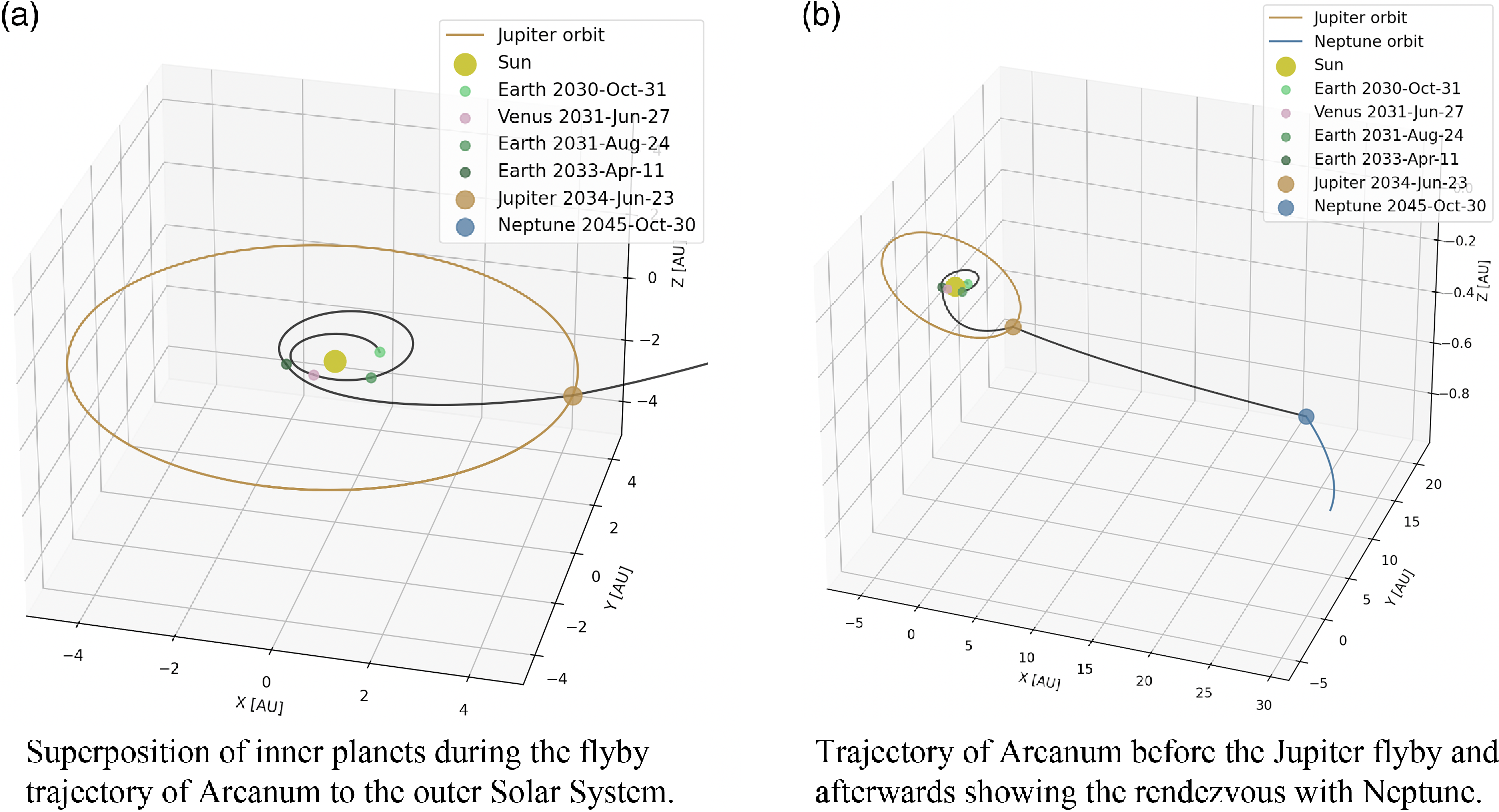
Figure 5. Trajectory of the Arcanum mission from Earth to Neptune.
Table 1. Trajectory information

4.0 The triton vehicles
A principal scientific interest of the mission is the Triton surface and subsurface environment. Triton follows a highly unusual retrograde orbit, suggesting its origin lies outside the Neptunian system. It is strongly believed that Triton is in fact a captured Kuiper Belt object (KBO), meaning it was formed in the outer reaches of the Solar System beyond Neptune. The limited observations performed on the moon so far, be those Earth-based or performed by Voyager 2, suggest the possibility of an internal ocean. A confirmation of these theories would overturn the currently held understanding of habitability in star systems given that potentially habitable worlds could form and remain sustained outside of the Goldilocks zone, or habitability zone, currently simply a function of distance from a star. The surface environment on Triton shows signs of renewal, an indicator of internal activity, heat and, therefore, potentially a subsurface ocean. Confirming and better quantifying these levels of activity – and any past activity – in the surface and subsurface is therefore a central theme of the science case for this mission. Access to these is facilitated through three modules: three penetrators and the soft-landing Bingham probe (Figs. 7 and 8). These, coupled with the Tenzing Triton-orbit manoeuvring unit, will launch and transit to Neptune together, with Somerville providing power, thermal and communications support for the lander on the journey. Once placed in a highly eccentric Neptunian orbit, the mated Triton vehicles will be released onto an intercept trajectory with Triton. This course will be set by the orbiter, minimising the fuel expenditure of the Triton vehicles’ subsystem and therefore maximising propellant available for the landing. This maximisation of propellant in turn aims to maximise the carrying capacity for scientific instruments capable of operating on the lander, and therefore the science return.

Figure 6. Colour-coded diagram of the Bingham lander.

Figure 7. Artist’s impression of the Bingham lander on descent to Triton’s surface.
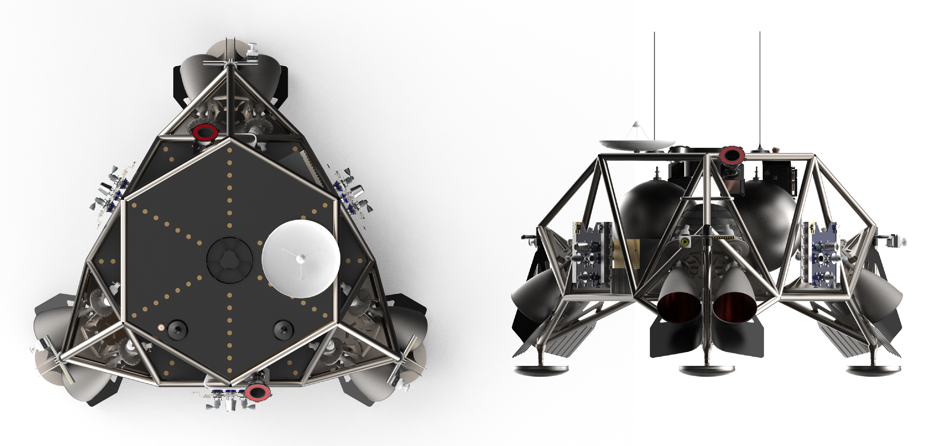
Figure 8. Rendering of the Bingham lander.
4.1 System overview
The nexus of the Triton vehicles is the Bingham lander. Once separated from Somerville, it will provide telemetry and power to Tenzing. Bingham will be mounted below Tenzing, while the penetrators will be mounted radially. At the time of deployment, the Triton vehicles will have a total wet mass of approximately 550 kg.
4.2 Tenzing orbital manoeuvring unit
4.2.1 Design overview
The Tenzing orbital manoeuvring unit is introduced to supply the fuel necessary for Triton capture, as well as to fine-tune the Triton orbit and facilitate precise landing site identification while minimising the mass of the final Bingham module itself. Tenzing will have two operating phases. The first, following separation from Somerville and before the separation of Bingham, will involve Tenzing functioning as an integrated service stage, demonstrating minimal autonomy. The second phase, following Bingham separation, will involve Tenzing functioning semi-autonomously. It will run on battery power and have basic orientation control and communications systems to coordinate the time and vector of deployment of the three penetrators.
4.2.2 Integrated systems
Where Tenzing differs from both a standard tug and part of a multi-stage lander is the degree of integration it has with Bingham, combined with the level of autonomy it maintains when separated. To improve mass efficiency, Bingham and Tenzing will have a single integrated propulsion system: Bingham’s primary rocket motors will be configured to drain fuel from Tenzing while the two modules are attached. The two will also feature integrated electronics, with Bingham providing power for Tenzing’s essential systems and Tenzing’s batteries taking over after separation. Unlike a tug, Tenzing is optimised to conduct the autonomous part of its mission with minimal complexity, thus simplifying the development process.
4.3 Bingham lander
4.3.1 Design overview
The Bingham lander’s objective is to provide a platform for the study of Triton’s atmospheric, surface and subsurface composition. To complete these objectives the lander must carry out a precise soft landing in Triton’s western hemisphere, in the region characterised by ‘cantaloupe terrain’. This area is thought to be the oldest portion of Triton’s crust and is pockmarked by geysers [Reference Sagan and Chyba18]. Bingham’s instrument suite will study the composition of these geysers as well as the ambient atmosphere. Bingham will also be a part of a planet-wide seismic experiment to study the internal dynamics of Triton by measuring the effect of the subsequent penetrator impacts and analysing residual and nominal seismic activity.
4.3.2 Payload
-
Cameras: The Arcanum mission will use two types of cameras – a high-resolution narrow-angle camera (NAC) and a medium-resolution wide-angle camera (WAC). The NAC will be responsible for capturing detailed images of Triton’s surface, providing crucial data for the study of its geological features and potential cryovolcanic activity. The WAC, on the other hand, will allow for broader context images of the moon’s surface and will assist in navigation and landing operations. Both cameras have flight heritage in the successful Mars Reconnaissance Orbiter’s HiRISE and CTX cameras [Reference Berman, Balme, Michalski, Clark and Joseph19], with necessary modifications to account for the harsher radiation environment and lower light levels around Neptune.
-
Seismometer: A highly sensitive, broadband seismometer will be included in the payload to measure seismic activity on Triton’s surface. This instrument will be based on the Seismic Experiment for Interior Structure (SEIS) used on NASA’s InSight Mars lander [Reference Compaire, Margerin, Monnereau, Garcia, Lange, Calvet and Dahmen20]. The seismometer will help us understand the internal structure of Triton, shedding light on its geological history, potential subsurface ocean and tidal interactions with Neptune.
-
Thermometer: A high-precision, low-temperature thermometer will be used to measure the surface and near-surface temperatures on Triton. Given that Triton’s surface temperature is estimated to be around 40 K, the thermometer will be specifically designed to function in such extreme cold conditions. This data will provide valuable insights into the thermal properties of Triton’s surface materials and the presence of any potential cryovolcanic or geothermal activity.
-
Aerosol collector and mass spectrometer: To investigate the composition of Triton’s thin atmosphere and any potential plumes, the mission will include an aerosol collector and mass spectrometer. The aerosol collector will gather particles from the atmosphere, while the mass spectrometer will analyse their composition. This system will be based on the Sample Analysis at Mars (SAM) instrument suite from the Mars Science Laboratory mission [Reference Stalport, Glavin, Eigenbrode, Bish, Blake, Coll and Szopa21]. Understanding Triton’s atmospheric composition will allow us to study its seasonal and long-term climate processes and examine potential organic molecules.
4.3.3 Structure
The primary structure of Bingham is Ti-6Al-4V titanium-alloy spaceframe consisting of two hexagonal frames 60° out of phase connected by cross braces. The chosen alloy has a low thermal conductivity, reducing the thermal losses from Bingham’s structure once in contact with Triton’s surface. This primary structure combines the main spacecraft bus, engine mounts and landing legs, reducing downstream integration issues between these subsystems. An interesting feature of the vehicle is the location of the six Leros 1C bipropellant engines being mounted to the primary structure. These engines are fixed at 30° to the vertical inside the structure of the landing legs (Fig. 6), an example where integrating assemblies in heritage designs into one structure reduces total mass. Additionally, this design is a low-mass solution to reduce contamination of the surface by the engine exhaust on descent, something present in the design of NASA Jet Propulsion Laboratory’s Skycrane used to land both the Curiosity and Perseverance rovers [Reference Martin, Mendeck, Brugarolas, Singh, Serricchio, Lee, Wong and Essmiller22]. Other efforts to reduce mass include using carbon-skin and aluminium hexagonal mesh core sandwich panels for the secondary structures and excluding complex active or passive mechanisms where possible.
A comparable structure would be that of Triton Hopper, where its structural mass is approximately 15% of the total mass [Reference Oleson and Landis23]. A preliminary analysis of Bingham’s structure shows that it would weigh just over 10% of the total mass. This optimised structural mass allows for a greater percentage of mass to be dedicated to the propulsion system, which extends the landing range of the vehicle.
This design philosophy will be continued as further analysis of the landing trajectories allows for the structure to be optimised.
Airbags were considered as a means of mitigating the forces experienced on the spacecraft during landing. They can allow reduced fuel loads and can make the spacecraft more durable when it comes to terrain conditions and orientation at impact. An issue that must be addressed is the effect of thruster plumes on the chemical structure of the landing site: there are concerns that these would invalidate some localised experiments. There is also the risk that melting of the local regolith, which is mostly composed of frozen nitrogen and water, due to engine plumes could cause the lander to become unstable [Reference Holler, Young, Grundy and Olkin24], something exacerbated if the landing site is already structurally weak. An airbag system would offer a solution to these difficulties. Heritage airbag landing systems include early Soviet lunar landers [Reference Gold25], where airbags were used after landing to surround and cushion an ejected payload module. More recently the NASA Mars Exploration Rover mission operated a more advanced system of lobed Vectran airbags arranged in a tetrahedral structure around the rover [Reference Crisp, Adler, Matijevic, Squyres, Arvidson and Kass26]. Also considered for this mission were airbags used purely to absorb impact shock of an already-righted spacecraft, in the same manner as the Boeing Starliner. Whilst airbags do help solve the problems of chemical contamination of the landing site, they lack the precision landing ability of engines and are still dependent on a partially powered descent to ensure the spacecraft is travelling at acceptable speeds at impact, given that any form of aerodynamic deceleration is impossible. The airbags must also deploy rapidly through the use of heavy gas generators and allow the spacecraft to right itself if it lands in an incorrect orientation, then retract to leave the lander set on a rigid structure, something essential for operation of the seismometers.
Opting for a full-powered descent aided by rigid landing legs was believed to be less operationally complex. The thrusters will be deactivated at an altitude that would cause minimal surface contamination or melting, and crushpads would absorb the remaining impact shock whilst the rigid leg design would minimise structural complexity. This manoeuvre requires careful consideration and calculation in the following stages of this mission design, beyond this Concept of Operations. Heritage landing leg designs involve telescoping legs with aluminium honeycomb crush core inserts and partially deformable domed footpads. The honeycomb inserts deform to absorb impact energy and an insert in the primary strut is more efficient as all forces are applied along the crushpad’s main axis, which is beneficial as lateral compression drastically reduces the material’s absorption efficiency. Telescopic legs are responsive to uneven ground conditions, improving the versatility of the lander, and the domed footpads exhibit greater strength than a flat pad of the same mass and can deform in response to uneven regolith, such as in the presence of rocks.
The choice of rigid landing legs with crushpads reduces structural mass and complexity as a result of the legs being integrated into the primary structure of the spacecraft. Therefore using this type of landing leg, along with the need to have a propulsion system regardless of whether or not airbags are used, is preferred [Reference Sahinoz27] and discussed in Section 4.3.4.
4.3.4 Propulsion
Of all the locations in which a soft landing has been attempted, the Earth’s moon is most similar to Triton. The composition and ambient temperature are significantly different, and these two factors will have to be considered for longer-term operations. For the landing, two other factors are key: the lack of an atmosphere and gravity. Mars is dissimilar to Triton due to its atmosphere, with an average surface pressure of 0.636 kPa. Triton’s atmosphere is around 385 times less dense on average. Mars also possesses much higher surface gravity at 3.72 m/s2. Asteroids, on the other hand, while also devoid of an atmosphere, have almost no gravity at all. For this reason, this study looked at the landing methods of lunar probes. The most common choice is propulsive landing via rockets. Most descent vehicles, from the Viking landers to the Skycranes of Curiosity and Perseverance, have used storable bipropellant hydrazine engines, with the exception of Starship and Blue Moon. These two landers, still conceptual, use cryogenic propellant. With the desire to maximise the lander mass available for instruments whilst minimising the total wet mass, a staged combustion engine cycle or similar would not be suitable. Looking to minimise complexity and simplify the construction of the spacecraft, while also limiting the potential for mechanical failure to arise during the coast phase of the mission, a pressure-fed or expander cycle system would appear most attractive. The expander cycle offers a high potential specific impulse but is hampered by the need for cryogenic fuel, the long-term management of which would add significant operational complexity to the spacecraft. To prevent boil-off, the fuel must be shielded from even minimal temperature fluctuations. To date, even advanced storage concepts would suit mission durations of 60–90 days, which is far too short for this mission and would require substantial mass gains to make it appropriate [Reference Doherty, Meyer, Motil and Ginty28]. As such, a pressure-fed system was selected. Such a system offers a relatively high specific impulse and a comparatively low associated ‘cost’ in dry mass due to the lack of required plumbing and turbopumps. The need to optimise propellant pressure against added fuel tank mass means there are practical limits on the combustion chamber pressure. However, the highly elliptical orbit and long descent trajectory, coupled with the low gravity of Triton, mean the lower chamber pressure is acceptable as the minimum required thrust for safe deceleration remains low.
The best precedent for unmanned interplanetary landers to date uses hydrazine-fuelled engines. The wealth of operational time and experience (technology readiness level TRL 9) of similar systems makes them an attractive choice. Hydrazine and its derivatives can be used in both monopropellant and bipropellant systems. The monopropellant option has more precedent when it comes to landers such as Phoenix and Schiaparelli Entry, Descent and Landing Module, as well as the Curiosity and Perseverance Skycranes (all designed for use on Mars), simplifying the ignition process and reducing the likelihood of a hard start, something which would be mission-fatal. However, when compared to our specific parameters, monopropellant engines prove too inefficient to conduct the full descent burn. Bipropellant options offer a solution to this problem, whilst minimising the increase in hardware complexity. Heritage missions using this technology also align more closely to this mission in that many of them, namely Beresheet and Surveyors 1-7, aimed to make soft landings on the surface of the Moon.
Fuel combinations considered are nitrogen tetroxide-monomethylhydrazine (NTO-MMH), hydrazine-NTO and hydrazine-MON (mixed oxides of nitrogen). Other alternative fuels are under consideration in the event that ESA moves to limit the use of hydrazine and other hazardous fuels. A stronger cleaner alternative with similar (if not improved) propulsive properties would be hydroxylammonium nitrate [Reference Spores, Masse, Kimbrel and McLean29].
With a view to minimising mission costs, commercial off-the-shelf components are again considered. Fortunately, the experience of European partners in delivering spacecraft propulsion systems for a number of applications means all of Bingham’s propulsion hardware is available off the shelf. Primary propulsion is provided by six Nammo Leros 1C Apogee rocket motors [30]. Reaction control thrusters will be Ariane Group 20N chemical monopropellant thrusters [31]. Hydrazine is stored in two Ariane Group surface tension tanks, and helium pressurant will be stored in two MT Aerospace high pressure tanks.
4.3.5 Power
Given that Bingham’s main theatre of operation will, like Somerville’s, be the outer Solar System, solar arrays would be an insufficient power system. Battery power alone would be insufficient for the mission’s duration but radioisotope thermoelectric generators (RTGs) provide a high-output long-term source of power. A promising future RTG fuel is americium-241. Americium RTGs are already being investigated extensively in Europe and have many promising characteristics in terms of availability and lack of required processing: Am241 is readily available in Europe from nuclear reactor waste processing, and at a much higher level of isotopic purity than Pu238, manufactured by Neptunium-irradiation. Although the specific power of Am241 is substantially lower than Pu238 (114.7 mW/g for Am241 vs 390 mW/g for Pu238), its longer half-life (432.2 years vs 87 years) means it will supply power more consistently for the duration of the mission [Reference Ambrosi, Williams, Watkinson, Barco, Mesalam, Crawford, Bicknell, Samara-Ratna, Vernon, Bannister, Ross, Sykes, Perkinson, Burgess, Stroud, Gibson, Godfrey, Slater, Reece, Chen, Simpson, Tuley, Sarsfield, Tinsley, Stephenson, Freis, Vigier, Konings, Fongarland, Libessart, Merrifield, Kramer, Byrne and Foxcroft32]. On this mission, a generator will supply 125 W of constant power at Triton, used to power essential systems and recharge batteries.
Supplementary power will be supplied by 7.6 kg of EaglePicher Technologies’ lithiated nickel cobalt aluminum oxide (LNCAO) rechargeable batteries, holding over 1,070 Wh of energy. These are chosen for their impressive spaceflight heritage, including Space Shuttle and Mars missions, and their favourable properties such as long life and good temperature tolerance. The batteries will be drawn upon during the most energy-intensive mission phases such as Triton orbit insertion and landing, supplying up to 500 W of power. A breakdown of power production and consumption across the six planned phases of Bingham’s mission is given in Table 2.
Table 2. Bingham power breakdown (W)

4.3.6 Avionics
As Bingham will be so far from the Sun, conventional Sun-sensitive orientation control would be ineffective. As such, implemented instead is a Triton horizon sensor system combined with conventional star trackers for orientation control. Such a proposed sensor system requires much further attention, and will be the subject of future studies. With communications lag times of approximately eight hours between Triton and Earth, the Bingham spacecraft will have to autonomously execute its descent and landing manoeuvres. Once terminal descent begins, Bingham will use terrain-relative navigation (TRN) to precisely select a landing site within the pre-determined landing zone. High cadence stereo multi-spectral imaging of the terrain during the descent by part of the science payload will allow for the characterisation and study of various geological features, but operationally allow automated TRN. Algorithms such as the simultaneous localisation and mapping (SLAM) algorithm are commonly used in robotics to allow navigation of an unknown environment while simultaneously building a map of the surroundings and avoiding hazards, and would be used in this case. This system will use the vehicle’s reaction control thrusters and primary motors, hovering if necessary, to avoid excessively uneven terrain, high gradients or other formations that could damage the vehicle. This system relies on input from optical cameras and Lidar data to generate an accurate map of the local area on the fly, as well as determine the vehicle’s velocity and orientation relative to the surface.
Bingham has been designed for a 1,100 m/s descent manoeuvre from orbit based on optimising the mass for the current trajectory. This number will be refined as the trajectory matures in the design phase and descent will be optimised using TRN to improve the landing performance.
5.0 Triton operations
5.1 Selecting landing sites
Approximately 40% of Triton’s surface was imaged by Voyager 2 (closest approach to Neptune: 25 August 1989, Triton’s South Pole was facing the Sun) at sufficient resolution to understand the terrain types [Reference McKinnon, Kirk, Spohn, Breuer and Johnson33]. However, this data is both out-of-date and incomplete, requiring further mapping of Triton before landing site selection which is discussed in Section 5.1.1.
Selecting landing sites is a time-consuming task, sometimes taking more than four years [Reference Golombek, Grant, Kipp, Vasavada, Kirk, Fergason, Bellutta, Calef, Larsen, Katayama, Huertas, Beyer, Chen, Parker, Pollard, Lee, Sun, Hoover, Sladek, Grotzinger, Welch, Noe Dobrea, Michalski and Watkins34] due to engineering and scientific requirements [Reference Pajola, Rossato, Baratti and Kling35]. Existing data and that acquired during the transfer to Neptune can be used for preliminary decision-making, whilst higher-resolution data acquired during the Triton orbital phase can be used to refine any decisions. Potential landing sites have been discussed in previous work [Reference McKevitt, Bornberg, Dixon, Ayin-Walsh, Parkinson-Swift, Morgan, Beegadhur, Criscola, Heinreichsberger, Simha Reddy Pappula, Bulla, Patel, Laad, Forder, Singh, Moor, Foghis, Wedde, McDougall, Kent and Raj6] and include areas characterised by geysers, which are known to move position over time, Cantaloupe Terrain in the western hemisphere and a latitude near the subsolar point for the exploration of cryovolcanism.
5.1.1 Mapping Triton
Constantly improving telescopes, particularly the James Webb Space Telescope (JWST), have the potential to provide new data before the arrival of Arcanum to Triton, with the JWST Science Working Group specifically mentioning the trans-Neptunian region as one of interest [Reference Sonneborn, Clampin and Hammel36–Reference Hammel, El Moutamid, Fletcher, Holler, Kelley, Melin, Milam, Nixon, Norwood, Parker, Rivkin, Santos-Sanz, Sonneborn, Stansberry, Tiscareno, Thomas and Villanueva39]. The telescope component of Somerville could also potentially be used to perform relevant observations during flight for preliminary terrain analysis.
In addition, orbiting of Triton by Tenzing will give mission planners more accurate data than that which currently exists. Therefore, a camera on Bingham for this orbital phase facing Triton is required. Such a camera will also help combat the problem of Triton’s changing surface, allowing up-to-date and high-cadence mapping of the surface both for science and landing purposes. Imaging equipment will require a surface spatial resolution of around 5 m to resolve various terrain types and indicators of activity, also allowing for areas of relative safety to be down-selected.
5.1.2 Expected surfaces changes
Triton has complex seasons due to Neptune’s axial tilt and the moon’s inclined orbit [Reference McKinnon, Kirk, Spohn, Breuer and Johnson33, Reference Schmude40], therefore changes of the surface and activity are expected.
Triton has large seasonal variations in its atmosphere. In 1983, Triton was approaching the maximum southern summer and was expected to have a dramatic increase in methane abundance within the century [Reference Trafton41]. This theory would be valuable to test during the descent through the atmosphere and may affect the currently accepted density model of Triton’s atmosphere, and therefore the trajectory of any descending spacecraft. A short summary of Triton’s changing environment can be found in Table 3. Here, warm and cold are relative, only representing an absolute temperature change of around 2 K.
Table 3. Seasons on Triton [Reference Schmude40]

5.1.3 Autonomy in landing site selection
Mission planners should be involved in the landing site decision-making process, using the newly gathered data. However, existing concepts of automation can be used to assist their work. A priority concept similar to that used on the Europa Clipper [Reference Wagstaff, Doran, Davies, Anwar, Chakraborty, Cameron, Daubar and Phillips42] would parse through real-time images of Triton and send back to Earth only the ones that are relevant in the next step of manual analysis, enabling much faster detection of key features such as geysers. Maps including different engineering cartographic data, geographical information system (GIS) maps, can be generated and used for representation and evaluation of constraints to find safe landing spots that fulfil scientific and engineering requirements [Reference Pajola, Rossato, Baratti and Kling35].
To further assist planners, machine learning (Bayesian networks, reinforcement learning, transfer learning) can be used for finding potentially suitable landing sites. Bayesian networks can represent the causal relationships between landing site variables (terrain safety, fuel consumption and scientific interest). The posterior probability of the model provides the certainty of a terrain region being safe for landing [Reference Serrano43]. Reinforcement learning, in combination with transfer learning, can be used for autonomous landing in unknown or barely known extra-terrestrial environments. Relevant physical phenomena learned by 3D mesh data from NASA can be used as a base for simulating Triton’s surface by using transfer learning with newly obtained data [Reference Ciabatti, Daftry and Capobianco44]. Upcoming missions, such as NASA’s Dragonfly quadcopter mission to Titan, will leverage such techniques [Reference Barnes, Turtle, Trainer, Lorenz, MacKenzie, Brinckerhoff and Cable2].
5.2 Ionosphere reflection experiment
Radio waves of different frequencies are a useful tool for remote sensing and measurement. A well-established technique, this has been successfully used onboard spacecraft such as Cassini [Reference Kliore, Anderson, Armstrong, Asmar, Hamilton, Rappaport, Wahlquist, Ambrosini, Flasar, French, Iess, Marouf, Nagy and Russell45] and New Horizons [Reference Tyler, Linscott, Bird, Hinson, Strobel, Pätzold, Summers and Sivaramakrishnan46] and, in the case of Arcanum, offers an interesting repurposing of already-essential communications equipment. For this use case, three different radio experiment setups have been identified:
-
(1) Radio occultation between Earth and Somerville.
-
(2) Radio occultation between Bingham and Somerville.
-
(3) Radio signals between the penetrators and Bingham, bounced off the Triton ionosphere.
Results from the Voyager 2 radio occultation experiment showed an unexpectedly strong ionosphere around Triton, with a single layer beginning at about 200 km and peaking at about 350 km. The peak electron density measured was about $23 \times {10^9}\ {{\rm{m}}^{ - 3}}$
at ingress and
$23 \times {10^9}\ {{\rm{m}}^{ - 3}}$
at ingress and $46 \times {10^9}\ {{\rm{m}}^{ - 3}}$
at egress [Reference Tyler, Sweetnam, Anderson, Borutzki, Campbell, Eshleman, Gresh, Gurrola, Hinson, Kawashima, Kursinski, Levy, Lindal, Lyons, Marouf, Rosen, Simpson and Wood47], the difference being down to the ingress location not being subjected to any sunlight during the previous Triton day. It is currently unknown how much ionisation is caused by the Sun and how much by interaction with Neptune. 1989, the year of the flyby, was during the solar maximum of solar cycle 22, the fourth strongest solar cycle on record [Reference Tyler, Sweetnam, Anderson, Borutzki, Campbell, Eshleman, Gresh, Gurrola, Hinson, Kawashima, Kursinski, Levy, Lindal, Lyons, Marouf, Rosen, Simpson and Wood47]. As the arrival of the Arcanum probes on Triton may occur during solar minimum or a much weaker solar maximum, it is important to consider how the intensity may have decreased. Assuming the peak density decreases by half at solar minimum, a lower peak density value of about
$46 \times {10^9}\ {{\rm{m}}^{ - 3}}$
at egress [Reference Tyler, Sweetnam, Anderson, Borutzki, Campbell, Eshleman, Gresh, Gurrola, Hinson, Kawashima, Kursinski, Levy, Lindal, Lyons, Marouf, Rosen, Simpson and Wood47], the difference being down to the ingress location not being subjected to any sunlight during the previous Triton day. It is currently unknown how much ionisation is caused by the Sun and how much by interaction with Neptune. 1989, the year of the flyby, was during the solar maximum of solar cycle 22, the fourth strongest solar cycle on record [Reference Tyler, Sweetnam, Anderson, Borutzki, Campbell, Eshleman, Gresh, Gurrola, Hinson, Kawashima, Kursinski, Levy, Lindal, Lyons, Marouf, Rosen, Simpson and Wood47]. As the arrival of the Arcanum probes on Triton may occur during solar minimum or a much weaker solar maximum, it is important to consider how the intensity may have decreased. Assuming the peak density decreases by half at solar minimum, a lower peak density value of about $13 \times {10^9}{{\rm{m}}^{ - 3}}$
is found during a day that receives no sunlight. However, further research must be completed to reach a more accurate picture of the expected density.
$13 \times {10^9}{{\rm{m}}^{ - 3}}$
is found during a day that receives no sunlight. However, further research must be completed to reach a more accurate picture of the expected density.
One experiment which would be performed by the Arcanum mission will measure the long-term changes of density at different heights in Triton’s ionosphere. To do this, the impact penetrators will emit radio pulses in the MF-band, which bounce off the ionosphere and are detected by Bingham. These pulse emissions of defined frequency and strength are timed by chronometers so that Bingham can determine the runtime and attenuation. The distance between the penetrators and Bingham, calculated using the respective data links to Tenzing, must be known precisely and be low enough so that the radio pulse can reach Bingham in one reflection off the ionosphere.
Whilst the surface of Triton is relatively smooth, larger terrain features may still interfere with the beam at large launch angles. At a launch angle of 90°, the beam will travel very close to the surface for at least a few kilometres. It is therefore advisable to have an approximate maximum launch angle of 80°. At this angle, the radius of Triton (1,350 km) and height of the layer (reflection will occur between 200 and 350 km) give a furthest distance of about 1,120 km between landing sites for a one-hop transmission.
6.0 Telescope
As an integral part of the Somerville orbiter, a telescope operating within the visible and near-infrared (0.3–1.5 µm), and with a 0.7 m aperture for the primary mirror, is proposed. An instrument with such capabilities, operating in the outer Solar System beyond the influence of sunlight scattered by interplanetary dust, zodiacal light, is regarded as a powerful tool in achieving a large number of science goals [Reference Bock, Beichman, Cooray, Reach, Chary, Werner and Zemcov48].
Other space-based observatories were used as a reference to define the design requirements for the Somerville telescope. A science-driven design method, such as has previously been proposed [Reference Stahl, Kuan, Arnold, Brooks, Knight and Martin49] considering the observation of KBOs and Planet-Nine-like objects whilst orbiting Neptune, was used to define the requirements of the optical system.
A standard configuration two-mirror Cassegrain reflector was proposed as a starting point in order to define the focal length and overall dimensions. However, a Ritchey-Cherétien (RC) scheme with a concave hyperbolic primary mirror is regarded as a more capable alternative as such arrangement reduces coma and spherical aberration. This configuration allowed for a reasonably simple starting point, meaning that values for volumetric sizing and mass budgets of the instrument, and therefore feasibility of the spacecraft, could be assured. It is likely that this configuration will be refined in the future. However, for the first iteration of an instrument capable of answering the mission’s science goals and continued design, the RC scheme is sufficient.
To begin the design process, a calculated focal length is inserted into established relationships for an optimally constructed optoelectronic telescope system [Reference Kurenkov and Koroleva50].
 \begin{align}f = \frac{{D{\rm{\;}}{\rho _{lim}}{l_{ps}}}}{{{\lambda _p}}}\end{align}
where D is the aperture diameter, ${\rho _{lim}}$
is the coefficient for resolution limit defined by the Rayleigh Criterion as
${\rho _{lim}}$
is the coefficient for resolution limit defined by the Rayleigh Criterion as $0.8086 \pm 0.08$
,
$0.8086 \pm 0.08$
, ${l_{ps}}$
is the size of each photodetector element and
${l_{ps}}$
is the size of each photodetector element and ${\lambda _p}$
is the average value of the selected wavelength range. The following geometrical parameters for the RC scheme were then calculated directly, resulting in the specifications shown in Table 4.
${\lambda _p}$
is the average value of the selected wavelength range. The following geometrical parameters for the RC scheme were then calculated directly, resulting in the specifications shown in Table 4.
Table 4. Telescope design specifications

Moreover, a 2D ray-trace simulation performed in ZeMax OpticStudio of the proposed configuration was performed, from which it was possible to define the curvature, sphericity and position of the focal plane (FP), primary mirror (M1) and secondary mirror (M2). The results are shown in Table 5 and Fig. 9.
Table 5. RC scheme, distribution and dimensions (m)


Figure 9. 2D ray trace for the two-mirror curved RC showing the focal plane (FP), primary mirror (M1) and secondary mirror (M2).
To determine the mass of the telescope, a previously proposed statistical model [Reference Malamed51] is used to calculate the approximate total weight of the optical system. Considering the aperture diameter as a defining feature, the model presented in Fig. 10 describes the equivalence in mass for an aperture up to 1.7m.

Figure 10. Mass analysis for the Arcanum RC two-mirror telescope.
7.0 Conclusions
Any space mission design requires a multifaceted approach, and Arcanum is no exception. As part of the ever-growing series of papers on this mission, here Conex Research presents their latest development work on the Triton segment of the mission, a suitable transfer trajectory to Neptune and specifications for the Somerville telescope.
Concepts for the next outer Solar System mission have long been proposed, but now the time is approaching where payload masses and cost reductions mean the science performed by such missions justifies the efforts needed to support them. Arcanum represents a study of the viability of such missions and should contribute towards the literature for developing future deep space exploration missions.
Acknowledgements
This work represents a truly international effort, uniting like-minded young researchers from around the world. The self-starting of this group, the completely remote working and their dedication and perseverance shown in the face of COVID-19 disruption bears testament to each and every character involved in the team.
Partners providing software and technical advice are thanked for their support and their belief in Conex Research – Northrop Grumman, Zemax, Sparx Systems, tukom, Innoslate and Sydereal Space. We would like to express our sincere gratitude to the anonymous reviewers for their insightful comments and constructive feedback, which significantly contributed to improving the quality and clarity of this manuscript.


 Open access