


1 Introduction
Orion[Reference Hopps, Oades, Andrew, Brown, Cooper, Danson, Daykin, Duffield, Edwards, Egan, Elsmere, Gales, Girling, Gumbrell, Harvey, Hillier, Hoarty, Horsfield, James, Leatherland, Masoero, Meadowcroft, Norman, Parker, Rothman, Rubery, Treadwell, Winter and Bett1], a high-power Nd:glass laser facility, commenced user experiments in 2013[Reference Hoarty, Allan, James, Brown, Hobbs, Hill, Harris, Morton, Brookes, Shepherd, Dunn, Chen, Von Marley, Beiersdorfer, Chung, Lee, Brown and Emig2]. It provides ten beamlines with 0.1–10 ns pulse duration (‘long pulse’), each with a specification of 500 J in 1 ns at 351 nm and two beamlines each with a specification of 500 J in 500 fs (‘short pulse’) at 1054 nm. To obtain increased temporal contrast, one of the latter beamlines may be frequency doubled. With the original capability[Reference Hillier, Danson, Duffield, Egan, Elsmere, Girling, Harvey, Hopps, Norman, Parker, Treadwell, Winter and Bett3] enhanced recently, up to 210 J in 500 fs is available at 527 nm[Reference Parker, Danson, Egan, Elsmere, Girling, Harvey, Hillier, Hussey, Masoero, McLoughlin, Penman, Treadwell, Winter and Hopps4]. For a programme of experiments at high energy density, laser pulses are delivered to a small target, positioned and synchronized to high accuracy.
The study presented here considers significant enhancement of the performance of the ‘short pulse’ beamlines. Nominal specifications for operation at the fundamental level (1ω) have been proposed by the user community, requiring an increase in pulse energy on target to 1 kJ in each beamline in a duration reduced to 200–300 fs. The specification at the second harmonic (2ω) is to obtain as great a proportion of this pulse energy as reasonably practicable in a duration no greater than 1 ps.
A conceptual design has been developed that meets the specification with the minimum of modification to the existing beamlines. To deliver the second harmonic, a relatively straightforward approach is described. However, a novel, more developed approach with the potential to deliver similar energy in a much shorter pulse has also been devised. This route to high peak power at the second harmonic is not limited to the Orion facility and could be applicable generally.
Designs have been developed with the support of numerical simulation[Reference Harvey5]. Details of the design and, for each mode of operation, an assessment of expected performance and critical specifications derived from it, are presented.
2 Conceptual design: operation at 1ω
2.1 Front end
At present, the front end consists of an oscillator, pulse stretchers and pre-amplifiers based on optical parametric amplification[Reference Hopps, Oades, Andrew, Brown, Cooper, Danson, Daykin, Duffield, Edwards, Egan, Elsmere, Gales, Girling, Gumbrell, Harvey, Hillier, Hoarty, Horsfield, James, Leatherland, Masoero, Meadowcroft, Norman, Parker, Rothman, Rubery, Treadwell, Winter and Bett1]. Spectral power in the output with a 20th-order super-Gaussian profile of 15 nm full width at half maximum (FWHM) has been assumed for the purposes of beamline design. It will be necessary to introduce an acousto-optic programmable dispersive filter (AOPDF) to achieve the shorter pulse duration required, through fine control of the spectral phase profile. No other modification of the front end is envisaged, except to amend the centre wavelength  ${\lambda}_0$ of all sub-systems to 1057 nm (see below), from the current value of 1054 nm[Reference Hopps, Oades, Andrew, Brown, Cooper, Danson, Daykin, Duffield, Edwards, Egan, Elsmere, Gales, Girling, Gumbrell, Harvey, Hillier, Hoarty, Horsfield, James, Leatherland, Masoero, Meadowcroft, Norman, Parker, Rothman, Rubery, Treadwell, Winter and Bett1].
2.2 Rod amplifier stage
Each beamline contains two rod amplifiers, which are passed twice. The two rods in each beamline differ, with one a phosphate glass (LHG-8) and the other a silicate glass (ED-2), to facilitate suitably broad bandwidth in the laser gain. While different options have been considered for reconfiguring the amplification in Nd:glass generally, requirements should be met without modifying the rod amplifier stage. The gain bandwidth may be increased sufficiently by increasing the contribution from the silicate rod amplifier. To be effective, however, this must be accompanied by a small change in the centre wavelength of sub-systems external to the laser amplifier, from 1054 to 1057 nm, so as to relax the impact of the upper bound on the wavelength that arises[Reference Hopps, Oades, Andrew, Brown, Cooper, Danson, Daykin, Duffield, Edwards, Egan, Elsmere, Gales, Girling, Gumbrell, Harvey, Hillier, Hoarty, Horsfield, James, Leatherland, Masoero, Meadowcroft, Norman, Parker, Rothman, Rubery, Treadwell, Winter and Bett1].
2.3 Disc amplifier stage
The aspiration to a pulse energy on a target of 1 kJ in each beamline informed the original design of the facility. A vacancy was included in order to accommodate an additional amplifier at 180 mm beam diameter. (Each amplifier contains three discs of LG-770.) Use of alternative glasses, such as variants of BLG-80[Reference Schott6], has been considered in the disc amplifiers, but no better compromise between output energy and bandwidth has been found.
Anticipating a change in the orientation of linear polarization, as dictated by the pulse compression (see below), the re-mounting of relevant components is expected, after rotation about the beam axis through a right angle.

Figure 1 Schematic layout (plan view) of the Laser Hall (left) and Compressor Hall (right), showing the new beam paths and components overlaid on the existing equipment. (Where they differ, the existing beam paths are shown with dashed lines.)
Chromatic aberration (CA) in refractive singlet lenses, used routinely in beam transport, has a significant impact on beamline performance[Reference Bor7–Reference Harvey9]. This will prevent achievement of the required pulse duration and it will be necessary to correct the aberration. The utility of diffractive components, which show axial CA of the opposite sign, has been recognized[Reference Bor10–Reference Néauport, Blanchot, Rouyer and Sauteret12]. Such components are established as correctors of CA in high-power beamlines, such as PETAL[Reference Blanchot, Behar, Berthier, Bignon, Boubault, Chappuis, Coïc, Damiens-Dupont, Ebrardt, Gautheron, Gibert, Hartmann, Hugonnot, Laborde, Lebeaux, Luce, Montant, Noailles, Néauport, Raffestin, Remy, Roques, Sautarel, Sautet, Sauteret and Rouyer13] and OMEGA EP[Reference Maywar, Kelly, Waxer, Morse, Begishev, Bromage, Dorrer, Edwards, Folnsbee, Guardalben, Jacobs, Jungquist, Kessler, Kidder, Kruschwitz, Loucks, Marciante, Mccrory, Meyerhofer, Okishev, Oliver, Pien, Qiao, Puth, Rigatti, Schmid, Shoup, Stoeckl, Thorp and Zuegel14], and they are the favoured option for Orion. They might be introduced, as elsewhere, immediately prior to spatial filtering of the beam, at 180 mm diameter or possibly earlier, at 140 mm diameter, to provide for removal of small-scale phase error that may arise. While proprietary routes for manufacture are available, a collaborative programme of development is currently in progress that seeks to exploit in-house capability, enabling manufacture on site[Reference Harvey, Egan, Aulsberry and Wheeler15].
2.4 Pulse compression
At present, the pulse compression in each beamline consists of a single pair of reflection gratings. Owing to the limited threshold for laser-induced damage, it has long been understood that the gold coating represents the fundamental constraint on an increase in pulse energy. Multi-layer dielectric (MLD) gratings, which show a substantially increased damage threshold in the relevant range of pulse duration[Reference Neauport, Lavastre, Razé, Dupuy, Bonod, Balas, de Villele, Flamand, Kaladgew and Desserouer16], are now available at large aperture. However, it is considered likely that otherwise like-for-like replacement is not available, with the groove profile implied at the current density (1480 mm–1)[Reference Hopps, Oades, Andrew, Brown, Cooper, Danson, Daykin, Duffield, Edwards, Egan, Elsmere, Gales, Girling, Gumbrell, Harvey, Hillier, Hoarty, Horsfield, James, Leatherland, Masoero, Meadowcroft, Norman, Parker, Rothman, Rubery, Treadwell, Winter and Bett1] not considered viable. In any event, increased bandwidth in the amplified pulse would enlarge the aperture required at the second grating and beyond, where the beam is laterally dispersed, to an extent that would not be cost-effective.
Therefore, the grating configuration must change. Given the high cost of replacement, the existing vacuum vessels shall be retained, fixing the geometry of the beams within. To resolve this situation, accommodating gratings of different groove density and a greater bandwidth, the pulse compression in each beamline is divided between two grating pairs in sequence (see Figure 1). The second (C2 = DG3, DG4) will be accommodated within one of the existing vacuum vessels, while the first (C1 = DG1, DG2) will precede it, located in space available in the Laser Hall and not evacuated. Support structures for the latter will be sufficiently robust to enable and retain alignment of the beamlines to the tolerances required. Separation into two differing grating pairs allows the new configuration to replicate the existing spectral phase change (to second and third derivatives, at least).
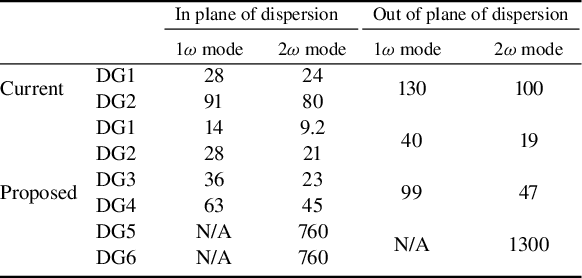
Table 1 Draft specifications for 1ω diffraction gratings.
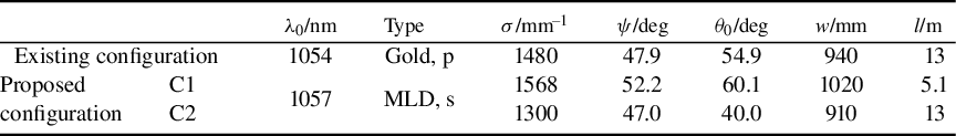
Notes: Specifications show groove density σ, angles of incidence and diffraction at the first grating ψ and θ 0 respectively, clear width w (based on 620 mm in the plane of the undispersed beam) and grating separation l. For the purposes of simulation, a circular clear aperture, truncated horizontally to top and bottom to a height of 620 mm, is used for the existing configuration; a rectangular aperture of the same height is assumed for the proposed configuration.
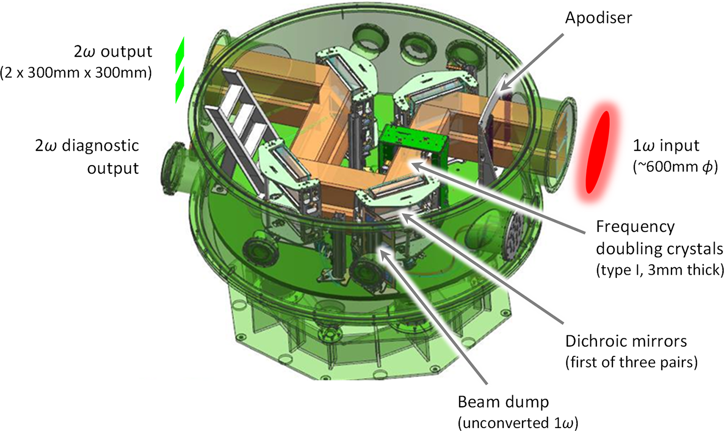
Figure 2 Auxiliary vacuum chamber in its present configuration.
The grating pair accommodated in the vacuum vessels (C2) must take a groove density smaller than the current value. The angle of incidence at DG3 must be comparable to the current value. If it is too small, the requirement for pulse energy cannot be met. If it is too large, the aperture of the gratings, already the largest components in the facility, becomes excessive. Together, these conditions restrict the range of practicable groove density to around 1150–1350 mm–1. They also imply that the angle of diffraction at DG3 is smaller than the angle of incidence, opposite to the current configuration of the pulse compression.
The additional grating pair in each beamline (C1) will be accommodated prior to the other as described above. Applying similar considerations, a higher groove density is implied and an angle of diffraction at DG1 that is larger than the angle of incidence.
The proposal is summarized in Table 1. Practicability is contingent on availability of efficient MLD gratings at these groove densities, but realistic designs have been established (see the Acknowledgement). In contrast to gold coating, they require s polarization. The laser-induced damage threshold required for each grating and the tolerances for misalignment have been determined (see the Appendix).
Although the complexity of the pulse compression is increased, a valuable benefit of multiple grating pairs is the option to oppose the lateral dispersions in order to reduce the effect overall. While the lateral dispersion in the compressed pulse is large at present (around 39 mm nm–1), in the proposed configuration it is all but eliminated, optimizing spatial filling at the critical final grating and beyond. Note that, in order to do this, the two pairs must be arranged so that the beam in each tracks laterally in the same direction (see Figure 1). This arrangement also reduces the sensitivity overall to input pointing/wavefront error, for a given pulse duration.
3 Conceptual design: operation at 2ω
Frequency doubling the compressed pulse in one of the beamlines is an important aspect of the facility capability. This is achieved in an auxiliary chamber separate from the compressor chambers (see Figure 2). However, an awkward feature of both the original installation[Reference Hopps, Oades, Andrew, Brown, Cooper, Danson, Daykin, Duffield, Edwards, Egan, Elsmere, Gales, Girling, Gumbrell, Harvey, Hillier, Hoarty, Horsfield, James, Leatherland, Masoero, Meadowcroft, Norman, Parker, Rothman, Rubery, Treadwell, Winter and Bett1, Reference Hillier, Danson, Duffield, Egan, Elsmere, Girling, Harvey, Hopps, Norman, Parker, Treadwell, Winter and Bett3] and the present installation, enhanced in aperture by segmentation with two beamlets 300 mm square in a vertical array[Reference Parker, Danson, Egan, Elsmere, Girling, Harvey, Hillier, Hussey, Masoero, McLoughlin, Penman, Treadwell, Winter and Hopps4], is the fact that the frequency doubling crystals are on the verge of being over-driven[Reference Harvey9]. Increased input intensity would lead to de-conversion and loss of efficiency. This would arise if CA in the beamline were corrected[Reference Harvey9], a realistic possibility in the near term in its own right[Reference Harvey, Egan, Aulsberry and Wheeler15], but much more so with the increased pulse energy and reduced pulse duration specified here for 1ω operation. In the latter case the likely consequence would be several cycles of conversion and de-conversion through the thickness of the crystals, and an unmanageable impact on laser performance.
Clearly, a thinner crystal would address this situation. Simulation suggests that converted pulse energy would be optimized at a reduced thickness of the order of 1 mm. While doubling of similar[Reference Mironov, Wheeler, Gonin, Cojocaru, Ungureanu, Banici, Serbanescu, Dabu, Mourou and Khazanov17] or much higher intensities[Reference Mironov, Lozhkarev, Ginzburg, Yakovlev, Luchinin, Khazanov, Sergeev and Mourou18, Reference Mironov, Lozhkarev, Ginzburg, Yakovlev, Luchinin, Shaykin, Khazanov, Babin, Novikov, Fadeev, Sergeev and Mourou19] in thin crystals has been investigated, no such component is available, or likely to become available in the near term, at the required aperture. Instead, we consider moderating the input intensity sufficiently to regain efficient conversion in available crystals.
This could be achieved simply by reducing the pulse energy, but this is clearly a poor strategy. As the input pulse would be shorter than at present by default, the converted pulse energy would inevitably fall below the current value.
Alternatively, we consider moderating the intensity at the crystals by controlling the temporal profile of the pulse (without significant loss). One obvious approach is to detune the otherwise well-compressed input pulse by mismatching the pulse stretchers and compressors. Unfortunately, while the pulse would then be longer and less intense, it would also be chirped, with a variation of instantaneous frequency through the pulse. Phase matching, which is achieved exactly at only one frequency (or a limited number of discrete frequencies), would therefore be compromised.
Fortunately, type I doubling near 1057 nm in potassium dihydrogen phosphate (KDP) shows group velocities for the coupled waves that nearly match at the phase-matching angle. Not only does this provide proof against loss of temporal overlap during conversion, but it also renders the phase-matching angle much less sensitive to frequency. This implies resistance to chirp, with the pulse phase matched relatively well over the whole bandwidth.
3.1 Basic scheme
For a given energy at the fundamental, there will be a corresponding detuning required to moderate the intensity at the crystals sufficiently to restore efficient conversion. The range of pulse duration permitted by the specification (up to 1 ps at 2ω) allows a generous upper bound on the energy that can be utilized (see below). Just as importantly, it appears that the necessary detuning can be introduced without the accompanying chirp compromising the conversion process. In fact, still greater chirp appears to be acceptable.
This approach has the advantage of leaving the post-compressor beamlines unchanged. On the other hand, it is unlikely to offer a meaningful increase in peak power, able to deliver increased energy only in a longer pulse. (It is compatible with enlargement of the aperture, segmented with a 2×2 array of beamlets, for example, although the further uplift in pulse energy would be accompanied by some degradation of temporal contrast on the target. The elimination of lateral dispersion in the compressed pulse precludes the softening of spectral clipping in the compressor otherwise derived from the roll-off to the periphery of the uncompressed spatial profile[Reference Hopps, Oades, Andrew, Brown, Cooper, Danson, Daykin, Duffield, Edwards, Egan, Elsmere, Gales, Girling, Gumbrell, Harvey, Hillier, Hoarty, Horsfield, James, Leatherland, Masoero, Meadowcroft, Norman, Parker, Rothman, Rubery, Treadwell, Winter and Bett1]. The consequent degradation of temporal contrast is strongest in the parts of the aperture that are peripheral in the dispersion direction.)
3.2 Advanced scheme
There is a further option for the moderation of intensity at the frequency doubling crystals in which a detuned pulse, having been frequency doubled, might then be compressed fully. This contrasts with a scheme in which a well-compressed pulse is doubled in a thin crystal, and its temporal profile is re-optimized subsequently after spectral amplitude and phase distortion in the crystal[Reference Mironov, Wheeler, Gonin, Cojocaru, Ungureanu, Banici, Serbanescu, Dabu, Mourou and Khazanov17–Reference Mironov, Lozhkarev, Ginzburg, Yakovlev, Luchinin, Shaykin, Khazanov, Babin, Novikov, Fadeev, Sergeev and Mourou19].
A further grating pair (C3 = DG5, DG6) is anticipated (see Figure 3). This is expected to be segmented as for the other optics in the auxiliary chamber. Other reflective components, such as multi-layer chirped mirrors or Gires–Tournois interferometers[Reference Kuhl and Heppner20], are unlikely to supply sufficient chirp. Assuming a familiar z-fold involving the first diffracted order accommodated in a (replaced) auxiliary vacuum chamber, the grating separation is limited to around 720 mm and the angle made between the incoming and outgoing beams at each grating may be in excess of 30°. The latter is far from ideal in typical circumstances, but efficient gratings will be assumed for the present. With the layout fixed, the groove density and angle of incidence are in a fixed relationship, effectively a single free parameter. In view of the limited flexibility, some assistance will be needed from the enhanced front end in the form of further fine adjustment of the spectral phase.
While only a relatively small chirp is needed to moderate the intensity sufficiently for the existing crystals, this leaves a problem for the post-conversion compressor. With the geometry constrained, the modest compression required implies a low groove density of 500–600 mm–1. At the reduced wavelength of the second harmonic, such gratings admit multiple diffracted orders and an efficient grating design is unlikely. To avoid this situation, the groove density, and with it the chirp at the crystals, must be increased significantly. Based on a fixed angle between beams at the gratings of  $\left|\psi -{\theta}_0\right|= 33.7{}^{\circ}$, producing a lateral separation of 400 mm over an axial separation of 600 mm, a groove density is selected (see Table 2) that just exceeds the minimum value. Beyond that, as it is a free choice, the alternative with the lower chirp ( $\psi >{\theta}_0$) is selected. Since the net effect requires a longer pulse at the crystals, with the input intensity moderated further, the crystal thickness must be increased to around 7 mm, although this reduces the difficulty of manufacture. The increase in groove density also increases the angle of incidence to a suitable value. While the real damage threshold of potential gratings remains to be seen, avoiding a low angle of incidence is clearly preferable for energy handling.

Figure 3 Schematic layout (plan view) of the amended auxiliary chamber configured for the 2ω mode, for one beamline only, showing the incoming beam at 1ω (red) and the continuing beam at 2ω (green). The post-conversion grating pair (DG5, DG6) has been added and the final dichroic mirror in the chamber (DM3) has been repositioned as shown (compare Figure 2). To revert to the 1ω mode, the unnecessary apodizer (A) and mirrors (M1 and DM3) are removed, allowing the full aperture beam to propagate straight through the vessel.
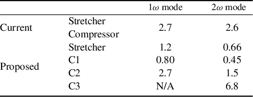
Table 2 Draft specifications for 2ω diffraction gratings.

Notes: Specifications show groove density σ, angles of incidence and diffraction at the first grating ψ and θ 0 respectively, clear width w (based on 320 mm in the plane of the undispersed beam) and grating separation l. The clear aperture should be rectangular.
Frequency doubling is desirable as it enhances the temporal contrast of the compressed pulse significantly[Reference Hopps, Oades, Andrew, Brown, Cooper, Danson, Daykin, Duffield, Edwards, Egan, Elsmere, Gales, Girling, Gumbrell, Harvey, Hillier, Hoarty, Horsfield, James, Leatherland, Masoero, Meadowcroft, Norman, Parker, Rothman, Rubery, Treadwell, Winter and Bett1–Reference Hillier, Danson, Duffield, Egan, Elsmere, Girling, Harvey, Hopps, Norman, Parker, Treadwell, Winter and Bett3]. Introducing diffraction gratings post-conversion has the potential to degrade the contrast through scattering. The extent of this effect is not easy to predict. On the other hand, it should be noted that the zero order at DG5 will be rejected spatially, passing out of the beamline. This enhances the removal of unconverted light, handled currently with dichroic mirrors alone[Reference Parker, Danson, Egan, Elsmere, Girling, Harvey, Hillier, Hussey, Masoero, McLoughlin, Penman, Treadwell, Winter and Hopps4].
With the intended configuration established, an immediate concern is the availability of a design for efficient gratings. As it will be highly desirable to retain all gratings in a vertical plane, use of s polarization at 1ω gratings and type I doubling implies p polarization at 2ω gratings. Fortunately, investigation suggests that a favourable, if somewhat demanding, design exists for p polarization (see the Acknowledgement). The laser-induced damage threshold required for each grating and the tolerances for misalignment have been determined (see the Appendix).
For fine alignment of a parallel grating pair, angular dispersion in the transmitted beam can be used as a diagnostic of misalignment. This can be observed using a broadband beam brought to focus. At present, the front end produces broadband pulses at a repetition rate of 2 Hz, which are sufficiently energetic after frequency doubling in the auxiliary chamber to be detectable at focus at the target position[Reference Parker, Danson, Egan, Elsmere, Girling, Harvey, Hillier, Hussey, Masoero, McLoughlin, Penman, Treadwell, Winter and Hopps4]. This can continue in the advanced configuration if the pulse compression at the fundamental is re-optimized temporarily, as for operation in the 1ω mode. While the converted pulse will be chirped subsequently by C3, this is inconsequential for time-integrated observation.
Although the design is beyond the scope of this paper, diagnostics of the performance in the 2ω mode will be provided.
Finally, it is necessary to consider the adjustment to the front end required in switching to the 2ω mode. Various options are available. (i) The simplest requires an increase in the single-pass equivalent grating separation in the pulse stretcher  $\Delta {l}_{\mathrm{s}}=70\;\mathrm{mm}$, which addresses the quadratic term in the spectral phase, and optimization of the residual cubic term using the AOPDF. (ii) Alternatively, the same effect may be achieved with a small increase of around 0.08° in the angle of incidence at the stretcher grating and a rather larger $\Delta {l}_{\mathrm{s}}=130\;\mathrm{mm}$. The change in alignment may be facilitated straightforwardly by the introduction of a weak wedge. (iii) The detuning of the stretcher required for the 2ω mode may be accommodated permanently and subtracted for the 1ω mode by means of an insertable grating pair. This would be transmissive, on account of the limited grating separation.
4 Expected performance
Performance of the beamlines at full power has been simulated. Wavefront error from optical components and the effect of spatial filtering have been neglected for simplicity. Background effects, such as amplified spontaneous emission (ASE), are not included. The spectral variation of diffraction efficiency has been represented in all cases. Pulse durations are rendered hereafter as effective values, that is, the integrated value of a temporal profile divided by its peak value, rather than the FWHM.
The bandwidths of spectral power expected immediately before and after the 1ω compressor are 7.9 and 7.7 nm, respectively (FWHM), and 8.2 and 8.0 nm, respectively (effective value).
Expected performance on the target is summarized in Figure 4. For comparison, this includes the beamlines in their current configuration, and the correction of CA as an intermediate step. While each beamline will continue to benefit from a deformable mirror in the disc amplifier stage[Reference Hopps, Oades, Andrew, Brown, Cooper, Danson, Daykin, Duffield, Edwards, Egan, Elsmere, Gales, Girling, Gumbrell, Harvey, Hillier, Hoarty, Horsfield, James, Leatherland, Masoero, Meadowcroft, Norman, Parker, Rothman, Rubery, Treadwell, Winter and Bett1], diffraction-limited performance on the target cannot be assured.
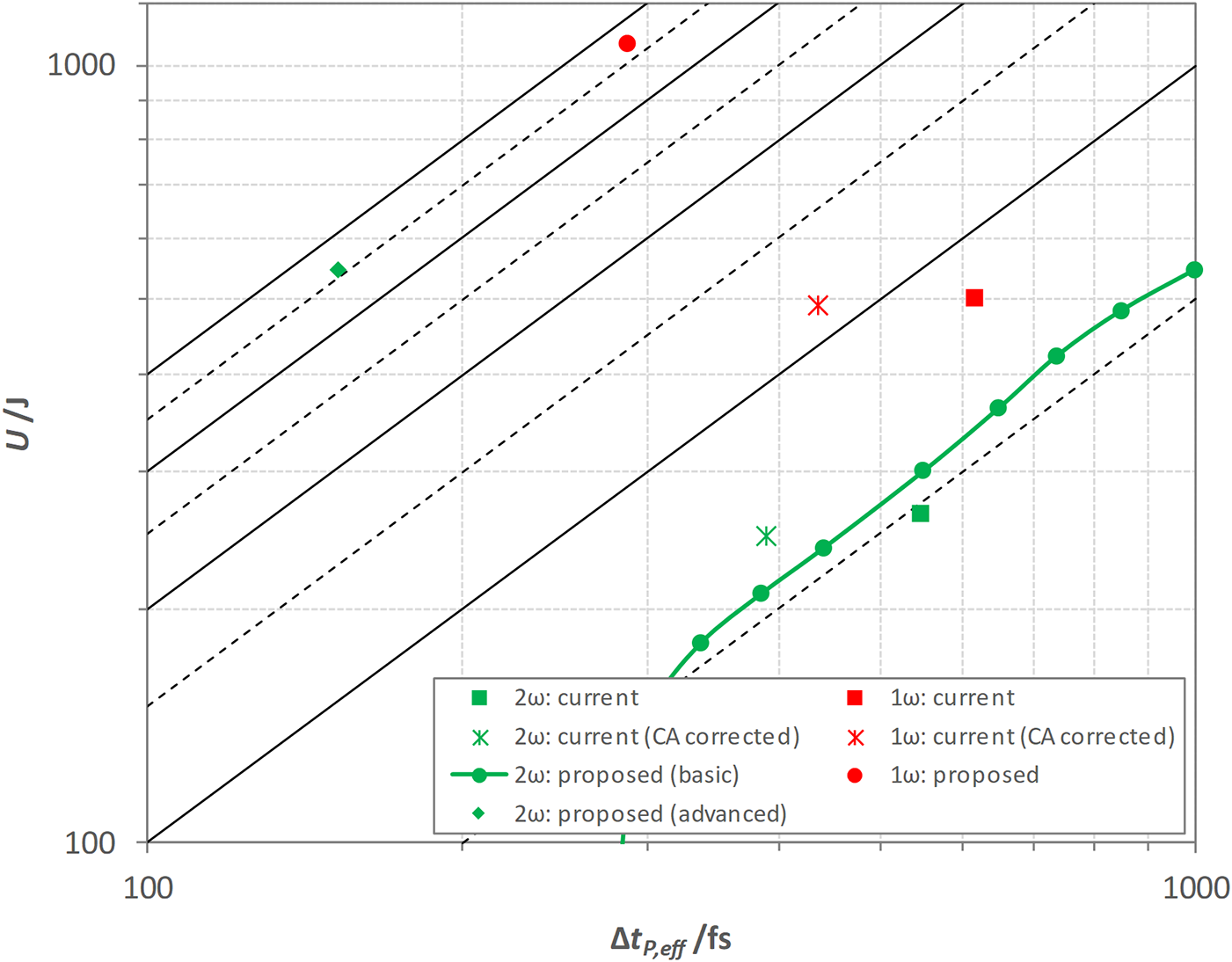
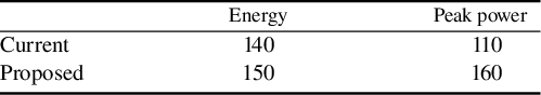
Figure 4 Expected performance on the target of the current and proposed configurations, showing pulse energy  $U$ and effective pulse duration of power $\Delta {t}_{\mathrm{P},\mathrm{eff}}$ on logarithmic scales. In the 2ω mode, the basic scheme is illustrated with a representative set of configurations. Loci of fixed peak powers (in whole and half PW increments) are shown for reference.
In the 1ω mode, some 1070 J in 290 fs (3.7 PW and up to  $2.7\times {10}^{22}\;\mathrm{W}\,{\mathrm{cm}}^{-2}$ peak) is expected on the target. This meets the specification, and represents a substantial uplift in peak power and intensity.
In the 2ω mode, performance depends on which option has been selected. (i) In the basic scheme, the change in effective stretcher grating separation  $\Delta {l}_{\mathrm{s}}$ is set, for a given energy at the fundamental, to maximize pulse energy on the target. Although a choice is available, $\Delta {l}_{\mathrm{s}}<0$ is favoured as it leads to a slightly steeper rising edge on the compressed pulse. The beamline is able to operate with up to 90% of full energy in the compressed pulse before the adjustment required ( $\Delta {l}_{\mathrm{s}}=-5.5\;\mathrm{mm}$) reaches the upper bound on pulse duration of 1 ps. At this point, up to 550 J (550 TW peak power) is expected on the target. Within that limit, a range of performance is available, with less energy in shorter pulses (see Figure 4), which may suit some experimental requirements. However, with existing performance expected to be around 270 J in 550 fs (490 TW peak power), the peak power is increased only marginally. (ii) In the advanced scheme, up to 550 J in 150 fs (3.6 PW and up to $6.4\times {10}^{22}\;\mathrm{W}\,{\mathrm{cm}}^{-2}$ peak) is expected on the target. The pulse duration is reduced significantly after doubling of the frequency bandwidth and fine optimization of the spectral phase, consistent with other studies[Reference Mironov, Wheeler, Gonin, Cojocaru, Ungureanu, Banici, Serbanescu, Dabu, Mourou and Khazanov17–Reference Mironov, Lozhkarev, Ginzburg, Yakovlev, Luchinin, Shaykin, Khazanov, Babin, Novikov, Fadeev, Sergeev and Mourou19]. Relative to the peak, the expected contrast in power is at least 8.0, 9.5 and 11.0 orders of magnitude at –5, –10 and –20 ps, respectively. The performance that may be available in terms of pulse energy, and power and intensity with high temporal contrast is remarkable.
5 Conclusions
Enhancement of the Orion laser facility has been considered and a conceptual design for modification of the ‘short pulse’ beamlines has been described. This meets the proposed specification, with operability expected to remain within reasonable bounds.
The expected performance represents a substantial uplift in capability, especially if the advanced scheme for the second harmonic is implemented. Although the practicability of critical components is not yet confirmed, this scheme is potentially applicable quite generally. It offers a route to ultra-high power at the second harmonic, with the accompanying advantage of high temporal contrast.
Appendix: Derived specifications
While the beamline design has been developed taking account of critical parameters, some formal requirements arise naturally from the expected performance.
1 Laser-induced damage threshold
Expectations of compressor gratings (see Table 3) are reasonable in C1 and C2[Reference Neauport, Lavastre, Razé, Dupuy, Bonod, Balas, de Villele, Flamand, Kaladgew and Desserouer16]. Prospects for C3 are not known with certainty. While there is good experience of MLD gratings operating at 1ω with ps and sub-ps pulses, no examples operating in the visible spectrum are known. Adverse scaling of damage threshold with wavelength and pulse duration is foreseeable. On the other hand, p polarization is specified for C3 (see Table 2). A significantly greater damage threshold for an MLD grating has been observed with p polarization compared with the more usual s polarization[Reference Hocquet, Neauport and Bonod21]. Manufacture and testing of sample gratings suitable for C3 offers a clear route to the reduction of uncertainty.
Table 3 Thresholds for laser-induced damage required for diffraction gratings.
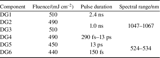
Notes: Thresholds are based on 50% contingency above the peak fluence in the beam, excluding small-scale spatial modulation, measured in the plane of the component.
It is believed that available damage thresholds will be sufficient elsewhere in the beamline.
2 Tolerances for misalignment
Misalignment of the beamline in various ways leads to a potentially significant reduction in output performance. The effects have been surveyed in relevant parameter spaces by adding the appropriate spectral phase errors.
2.1 Output near the transform limit
This applies to operation in the 1ω mode and in the 2ω mode in the advanced scheme. For full power shots, estimates for selected tolerances are shown in Tables 4–7.
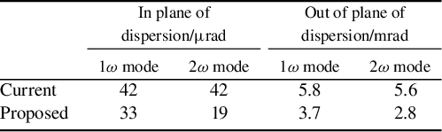
Table 4 Estimated tolerances (μrad) for grating pointing (parallelism) in the 1ω mode and the 2ω mode in the advanced scheme.
Notes: Tolerances are based on a nominal 10% loss of peak power on the target. With gratings mounted with grooves vertical, the tolerances in and out of the plane of dispersion relate to the angles of azimuth and elevation, respectively. In the 2ω mode, only the lower deck of C3 is considered to be misaligned and, for misalignment of C1 or C2, the resulting pointing error in the semi-compressed pulse is considered to be corrected prior to frequency doubling.
Tolerances for parallelism (grating pointing) in pulse compressors are shown in Table 4. With the spectral phase errors arising from misalignment varying linearly with position in the aperture, simple analysis implies that the tolerances should vary essentially in proportion to pulse duration. The requirements are clearly more challenging than at present, but should be manageable. They are relaxed in C3, as expected from the small size of this compressor.
Tolerances for grating separation are shown in Table 5. With the spectral phase arising from mis-setting being spatially uniform, simple analysis implies that the tolerance should vary quadratically with pulse duration. All should be manageable physically, although in the 2ω mode those for the stretcher and C1 are rather tight, the former compounded by the multi-pass configuration[Reference Hopps, Oades, Andrew, Brown, Cooper, Danson, Daykin, Duffield, Edwards, Egan, Elsmere, Gales, Girling, Gumbrell, Harvey, Hillier, Hoarty, Horsfield, James, Leatherland, Masoero, Meadowcroft, Norman, Parker, Rothman, Rubery, Treadwell, Winter and Bett1].
Table 5 Estimated tolerances (mm) for (single-pass equivalent) grating separation in the 1ω mode and the 2ω mode in the advanced scheme.
Notes: Tolerances are based on a nominal 10% loss of peak power on the target.
Table 6 Estimated tolerances for beam pointing into the 1ω pulse compression in the 1ω mode and the 2ω mode in the advanced scheme.
Notes: Tolerances are based on a nominal 10% loss of peak power on the target. In the 2ω mode, the tolerances reflect the effect of misalignment on the operation of the grating pairs only. The direct effect of the pointing error on the frequency doubling process is excluded.
Table 7 Estimated tolerances (μrad) for the angle between the beam within the frequency doubling crystals and the optical axis of the material in the 2ω mode in the advanced scheme.
Notes: Tolerances are based on a nominal 10% loss of either energy or peak power on the target.
Tolerances for beam pointing into the 1ω pulse compression are shown in Table 6. Once again, spectral phase error is spatially uniform and tolerances are expected to vary quadratically with pulse duration. However, the consequent reduction in the proposed configuration is offset by the deliberate opposition of the two grating pairs, in which the angles of incidence vary with pointing error in the plane of dispersion in opposite senses. In the 2ω mode, tolerances on the pointing into C3 only (not shown) are particularly relaxed (>20 mrad).
Tolerances for the angle between the beam within the frequency doubling crystals and the optical axis of the material are shown in Table 7. Unfortunately, as the latter also lies in a horizontal plane, the pointing error to which the grating pairs are more sensitive is also that to which the crystals are more sensitive.
2.2 Output away from the transform limit
This applies to operation in the 2ω mode in the basic scheme. Although it is a simple approach to mitigation of excessive intensity at the existing frequency doubling crystals, it is complicated by operation away from the transform limit. For a given drive, there is a significant difference in the settings of pulse compression that maximize energy (the default) and peak power on target (and in the tolerances that arise at each setting). A compromise setting may be appropriate. Some judgement may be exercised on the optimum setting for a given experiment.
Tolerances in peak power are generally comparable with the advanced scheme (except for grating pointing out of plane, which is several times more relaxed). However, a compromise setting reduces the tolerance of both energy and peak power to pointing of the frequency doubling crystals by approximately half.
Acknowledgement
Work relating to the design and expected performance of gratings in the proposed configuration was undertaken by Plymouth Grating Laboratory. This is gratefully acknowledged.


 Open access