


Introduction
It is well known that lake ice is generally composed of characteristic columnar crystals and usually displays a candle-like structure when it begins to melt in the spring. In this state it is called candle ice, and it is very useful when a large amount of ice is needed, because ice with this structure is easy to crush.
It was suggested by Reference Nakaya and BushnellNakaya (1959) that a piece of candle ice may not be a single crystal, but may be composed of many crystals. He pointed out that the boundaries between crystals of a single candle might be different in nature from the boundaries between adjacent candles, and that the latter boundaries might be much more easily melted by radiation than the former ones. The former boundaries might be called sub-boundaries, or small-angle boundaries as was suggested for lake ice (Reference KnightKnight, 1962) and for the ice of ice island t-3 (Reference Muguruma and HiguchiMuguruma and Higuchi, 1963). One purpose of the present study is to clarify the nature of such different kinds of crystal boundaries with respect to impurity content in the boundary.
The peculiar appearance of the ice at Peters Lake was reported by Reference Barnes and BushnellBarnes (1959) and Reference KnightKnight (1962); two types of ice with predominantly vertical and horizontal c-axes were observed in two distinct areas of the lake. It was shown by an aerial photograph that the former ice was white while the latter was darker. The crystallographic orientation could also be determined at a glance at an early stage of the melt season. This interesting fact stimulated the authors to try to clarify the cause of these two types of ice and to investigate the differences in their decay with particular emphasis on their physical properties.
Field investigation of the ice at Peters Lake was undertaken within the months of March and April 1962. Unfortunately, the two types of ice pointed out by Reference Barnes and BushnellBarnes (1959) and Reference KnightKnight (1962) were not found during that period. Although this curtailed the research programme, the difference in ice conditions between 1962 and the previous years suggested some ideas as to the cause of the two types of ice.
Before the field work was done at Peters Lake, a tentative investigation on lake ice was made at Lake Nukabira, Hokkaido, in January 1962 when experimental equipment was being tested. The data obtained at Lake Nukabira were helpful in understanding the appearance of the ice at Peters Lake; accordingly the observations are compared with each other.
Description and Auxiliary Data
Peters Lake is Iocated at lat. 69° N. and long. 145° W. in north-eastern Alaska. The lake lies wholly within a narrow glaciated valley, whose steep sides rise sharply from the water. The direction of the deep valley is such that winds blow either from the north or south (Fig. 1).

Fig. 1. Map of Peters Lake showing locations where ice samples were obtained
Water temperature was measured weekly by lowering a thermistor at one site (site 35 in Figure 1) in the deepest part of the lake. Figure 2 shows the temperature profiles. The water temperature was 0° C. in the surface layer and about 3° C. at the bottom of the lake at a depth of about 45 m. There was no great variation throughout the period, but towards the end of the period there was a slight increase below 10 m. depth. Though the lake water was fairly stable during the season, the formation of an unstable water layer could be noticed between the water layers of 5 m. and 10 m. depth.
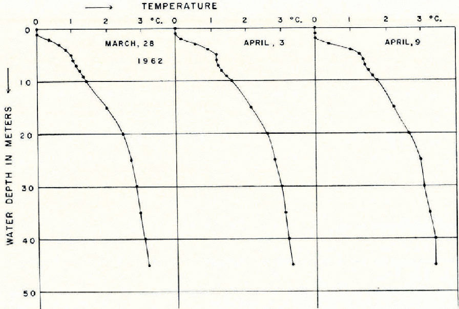
Fig. 2. Profiles of water temperature
Ice temperature was also measured daily at one site (site 2 in Figure 1) by means of thermistors whose cables were frozen into the ice. The thickness of ice at this site was 142 cm., so the three depths of 50, 100 and 130 cm. were chosen for the measurements. Ice temperature showed a tendency to increase at all depths in the ice towards the end of occupancy of the site (Fig. 3). The phase lag of the curve for 50 cm. depth compared with that for 100 cm. depth is clearly seen to be one day (Fig. 3). The fact that the temperature at a depth of 130 cm. was above 0° C. seems to have been due to malfunction of the thermistor.

Fig. 3. Daily change of ice temperature
Ice samples were obtained either with a 3 in. (7.6 cm.) diameter corer or by sawing out cubes with about 30 cm. sides. Samples were taken at 45 sites on Peters Lake covering the whole area of the lake (Fig. 1). Core drilling through the entire thickness of the ice was carried out at 20 sites and drilling down to 1 m, depth was done at 23 sites. Surface ice samples, obtained by sawing blocks of ice, were taken at 11 sites. At Schrader Lake, which is at the northern end of the valley, core samples were taken at 2 sites in order to ascertain whether there was any difference in ice structure from that at Peters Lake.
Ice Thickness
The thickness of ice and the depth of snow cover were measured at 20 sites each week. The increase of ice thickness was also measured weekly at 3 sites (sites 31, 35 and 34 in Figure 1); these points represented typical locations of different ice thicknesses on the lake. The average ice thickness was about 150 cm. at the end of March for both Peters and Schrader Lakes. The thickness varied considerably over the lake surface and a difference of about 50cm. was observed. The thickest ice measured was 172 cm. at site 34 in Figure 1; the thinnest ice was 123 cm. at site 25 in Figure 1. The variation in thickness can be explained by the differences in snow cover or exposure to wind. As shown in Figure 4, there is a good correlation between the ice thickness and the depth of snow cover. The area along the eastern side of the lake, particularly in the area to the north of the camp (area “B” in Figure 5), had comparatively less snow cover and thick ice. On the other hand, the west coast area in the central part of the lake (area “A” in Figure 5) had a thick snow cover and thin ice. The increase of ice thickness was about 0.5 cm./day. Because of the short period of observation, it was impossible to detect the difference of increase of ice thickness depending upon the location. Before the end of the field work there was no sign of melting in the snow and ice.
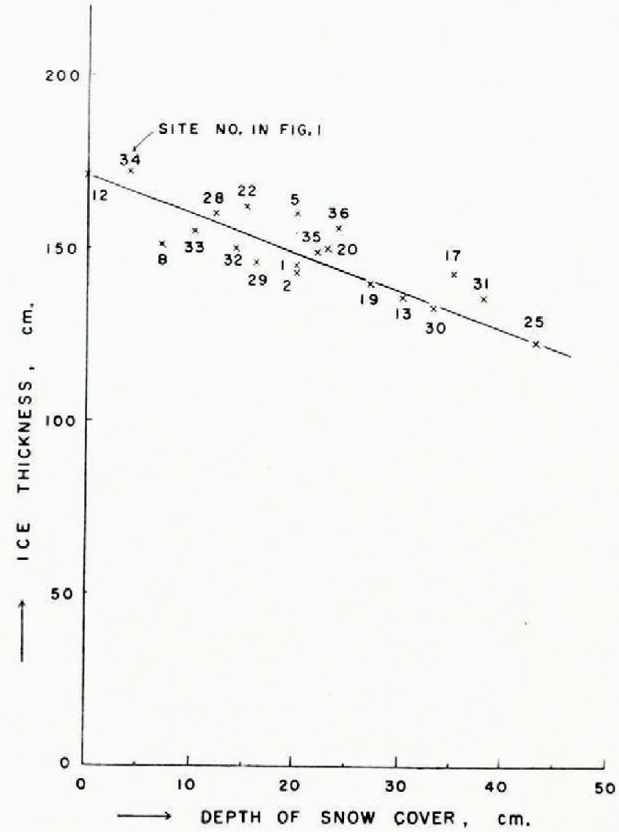
Fig. 4. Relationship between the thickness of ice and the depth of snow cover

Fig. 5. Distribution of the thickness of ice and the depth of snow cover over the entire area of Peters Lake
Ice Structure
The size and the c-axis orientation of the ice crystals were studied by means of rubbings of etched ice surfaces, by the use of polarized light and by observing Tyndall figures produced with artificial radiation. Vertical and horizontal cross-sections of the samples photographed in polarized light were prepared in such a way as to be sufficiently thin to allow light to pass without giving interference colours. The crystal grains observed were predominantly columnar in shape with irregular cross-sections and nearly vertical boundaries. This is a characteristic feature of candle ice. A block of candle ice separates into component candles when exposed to solar or artificial radiation, since melting starts chiefly along the crystal boundaries. An individual candle which had been separated from the block by using the radiation from an infra-red lamp was in its entirety a single crystal. There was no difference in that feature from the candle ice observed on t-3 (Reference Muguruma and HiguchiMuguruma and Higuchi, 1963). Since solar radiation was not strong enough to cause internal melting of the ice during the period of study, no vertical tubules which characterize candle ice were found to separate individual crystals.
Figures 6 to 9 are photographs of typical vertical sections of ice cores at site 35. Their horizontal cross-sections at various depths are shown in Figures 10 to 13. These figures illustrate well the increase of grain-size with ice depth. Since the drilling crushed the surface cores, the appearance of the ice structure at the surface cannot be presented in this series of illustrations.

Figs. 6 and 7. Vertical sections of an ice core from site 35; under crossed polaroids

Figs. 8 and 9. Vertical sections of an ice core from site 35; under crossed polaraids

Figs. 10, 11, 12 and 13. Horizontal sections of an ice core from site 35 at various depths; under crossed polaroids
(a) Small-angle boundary
Very faint textures in each grain can be noticed if these photographs are examined carefully. These slight textures show the existence of small-angle boundaries which are well known in the dislocation theory of crystals. These might be called sub-boundaries, referred to by Reference KnightKnight (1962).
Small-angle boundaries in ice crystals were beautifully shown by Reference NakayaNakaya (1958). A detailed study of the stress-induced movement of the small-angle boundaries of ice crystals was carried out by Reference Higashi and SakaiHigashi and Sakai (1961), with an interpretation of activation energy of the movement in terms of dislocations. Indubitably the formation of such boundaries, as observed above, is due to internal strain. Considering the freezing process of lake water and its subsequent contraction at low temperatures, the formation of small-angle boundaries in lake ice would be a common phenomenon.
The nature of a small-angle boundary is quite different from that of the boundary between adjacent crystals, because the melting starts chiefly along the boundary. The latter boundaries are expected to contain far more impurities than the former ones, which are considered to have the same impurity content as the other parts of a crystal. Though this fact is worth further investigation, in the present study it was difficult to detect such a difference.
(b) Orientation of the c-axis
The orientation of crystals was studied by observing Tyndall figures produced by radiation from an infrared lamp and by the use of polarized light. When bulk ice is exposed to this radiation, the boundaries are etched and become visible. Figures 14 and 15 are the prints of carbon rubbings which reveal both the size of the grains and the orientations of their c-axes. The numerous short bars seen in the rubbings are the marks of Tyndall figures, which show the orientation of the basal planes of the crystals if they are normal to vertical or horizontal sections. The clear prints of minute hexagonal figures seen on the right-hand side of the rubbing from site 19 in Figure 14 are also Tyndall figures showing completely horizontal c-axes. Two grains in the upper part of the rubbing at site 2 in Figure 14 show nearly vertical c-axes. This is an exceptional case. As far as the core samples obtained at 43 sites are concerned, all of the crystals below 30cm. depth had their c-axes predominantly horizontal. Reference KnightKnight (1962) reported in 1961 that about half the surface ice above 60 cm. depth on Peters Lake was orientated with the c-axes vertical and the other half horizontal.

Fig. 14. Carbon rubbings of vertical sections of ice cores at 100 cm. depth from sites 2 and 19, Peters Lake, showing grain boundaries and Tyndall figures

Fig. 15. Carbon rubbings of horizontal sections of an ice core at 0 and 133 cm. depth from site 30, Peters Lake, grain boundaries and Tyndall figures
The attempt to obtain surface cores down to 10 cm. by drilling was unsuccessful, so surface ice cubes with 30cm. sides were taken at 11 sites in addition to core samples in order to investigate the detailed profile of the c-axis orientations in the surface layer of ice. The vertical and horizontal sections of the ice in the surface layer at site 2 are shown in Figures 16 to 18.
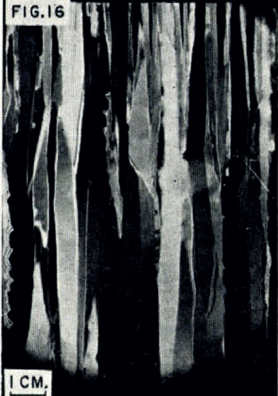
Fig. 16. Vertical section of the surface layer of ice at site 2; under crossed polaroids

Figs. 17 and 18. Horizontal sections of the surface layer of ice at 0 and 30 cm. depths at site 2; under crossed polaroids
The crystals have a very fine-grained appearance (compare Figures 16 and 17 with Figures 6 and 10). Grain-size increases with ice depth, as is shown in these figures. In order to obtain the statistical distribution of the c-axis orientation, component candles were separated from a block of ice by the use of artificial radiation. A separated candle was then placed in such a way that the basal plane of the crystal was normal to the observed surface, by observing the Tyndall figures. In this way, the orientation of the c-axis could be determined to an accuracy of 5 degrees. Figure 19 shows four histograms for different sites giving the statistical distribution of c-axis orientation. The orientation of the c-axis, θ, is taken as the deviation of the c-axis from the normal to the water surface. The ice with predominantly vertical c-axes could not be found even in the surface layer of the ice (Fig. 19). The ice with vertical c-axes was observed in only 1–2 per cent of the total number of grains in the surface layer above 30 cm. depth. From the features of the profiles of the c-axis orientations, the ice at Peters Lake in 1962 had a predominantly horizontal c-axis orientation, and this was uniform all over the surface of the lake.

Fig. 19. Histograms of the c-axis orientation of the surface ice at four different sites
(c) Grain-size
As is shown in Figures 6–18, grain-size increases with the depth of ice. The increase in grain-size is much more enhanced in a vertical direction in contradistinction to a horizontal direction, because of the characteristic nature of lake ice. Grain length in a vertical direction was about 2–5 cm. in the surface layer with an increase to about 10 times as long (30–50 cm.) near 100 cm. depth. The average grain-size at various depths below the surface was obtained by counting the number of grains in horizontal sections. The size ranged from 0.07 cm.2 at the surface to 5.4 cm.2 at 100 cm. depth. A fairly good correlation between grain area and the depth of ice was obtained from the surface to about 100 cm. depth as is shown in Figure 20. This can be expressed by the formula
where S is the grain area in cm.2 and d is the depth of ice in cm. This relationship is no longer applicable below 100 cm. depth. The appearance of the change in grain-size at various depths can be seen in Figures 10 to 13, and 17 and 18, whose numbers are listed in Figure 20.

Fig. 20. Relationship between grain area and the depth of ice
No difference in ice structure was noticed between Peters and Schrader Lakes during the present investigation.
(d) Ice of radial structure
Ice cores taken from refrozen holes, where the entire thickness of the ice was drilled through, showed a beautiful radial structure in horizontal cross-section as is revealed in Figures 22 and 23. These figures depict upper and lower parts of the cores whose vertical sections are shown in Figure 21. The radial lines in the ice undoubtedly show the grain boundaries, and this ice is characterized by a fine central tube. This must have been formed during preparation of the thin sections, because the grain structure at the centre of the core is very fine and quite different from that at the periphery as can be noticed in Figure 21. The increase in grain-size with the depth of ice can be seen even over a 10 cm. difference in depth in this peculiar structure of the ice.

Fig. 21. Vertical sections of ice with a radial structure; under crossed polaroids

Figs. 22 and 23. Horizontal sections of ice with a radial structure; under crossed polaroids
Ice with a radial structure and characterized by a narrow tube at the centre was found in the ice at ice island t-3 (Reference Muguruma and HiguchiMuguruma and Higuchi, 1963). Most of the radial lines in the ice were found to be boundaries between single crystals. The size of a single crystal was more than 50 cm. in its greatest dimension. The origin of this peculiar pattern in the ice was considered to be the result of the freezing of water in a tunnel. Ice with a radial structure, observed in a refrozen ice hole at Peters Lake, showed in miniature the same type of ice as that observed at t-3. The speculation offered in the previous work of Reference Muguruma and HiguchiMuguruma and Higuchi (1963) is clearly sustained by the present study.
Impurity Along Grain Boundaries
Though it was desirable to devise some more sensitive means of detecting any trace of impurity in grain boundaries, the measurement was limited only to electrical conductivity of fresh melt water from the ice. The electrical conductivity was measured by an alternating current Wheatstone bridge between platinum-plated electrodes immersed in water in a plastic container cell of 18.5 cm.3. Bulk ice of about 500 cm.3 was subjected to melting by the radiation from an infra-red lamp. At first, the ice block was rinsed with water which had been repeatedly purified with an ion exchange resin such that the specific conductivity of the melt water in the containers would be 0.5–0.8 micromho/cm. The specific electrical conductivity of the purified water was always about 0.5 micromho/cm. Ice samples of a pyramidal shape were prepared so that the melt water would drop into the container without contamination. The samples were supported by a plastic ring in such manner as to make the contact area between the sample and the support small enough to avoid any contamination of the melt water. Thus, the measurement was made repeatedly, changing the melt water in the container each time. About 10 measurements could be done with each sample. After ten measurements the candling of ice crystals was so enhanced as to cause separation into individual candles, and the sample could no longer be supported by the ring.
Since melting started chiefly along the grain boundaries, initial melt water was expected to contain much more impurity than the last melt water. It is considered that the melting of crystals themselves rather than the melting of the grain boundaries might be pronounced near the end of the melting process. The results of tests on ice from four different sites are shown in Figure 24. Solid lines in that figure indicate the curve obtained for the surface ice layer which contains many grains, and dotted lines show the curve obtained at 30–40 cm. depth at sites 40 and 42, and at 140–150 cm. depth at sites 1 and 35. All the curves have a tendency to decrease from the first to the second in the sequence number. This shows that the initial melt water contains impurity from the boundaries.

Fig. 24. Change of specific electrical conductivity in an ice sample, using the ice samples from sites 40, 42, 1 and 35
However, it was observed that the melting of boundaries was most pronounced between the third and sixth in the sequence number under the test conditions. From this fact a peak in the curve was expected between these numbers in the sequence. Such a peak was also expected to be less prominent in the crystals which consisted of a small number of grains, but Figure 24 shows that the results could not substantiate any such expectation. The data for measurements of specific electrical conductivity with respect to grain number are summarized in Figure 25. The values of conductivity in Figure 25 were determined from several measurement values which agreed fairly well with each other. No correlation between grain number and impurity content was detected. Specific electrical conductivity of the ice at Peters Lake ranged from 0.8 to 1.4 micromho/cm., which is of nearly the same order of magnitude as that of the ice of Mendenhall Glacier, Alaska (1 micromho/cm.) (Reference HigashiHigashi and others, in press).

Fig. 25. Average specific electrical conductivity with respect to number of grains
Investigation at Lake Nzukabira
(a) Description
Lake Nukabira is an artificial lake impounded by a dam for the purpose of producing hydro-electricity. This lake is located in the central part of Hokkaido (Fig. 26). As can be seen in Figure 26, the lake lies within a fairly steep-sided valley in the southern area, while it is surrounded by gentle slopes in the northern area. Wind blows either from a northerly or southerly direction along the length of the lake. There is a long and narrow bay at the south end of the lake, where there is relatively little wind. The differences between the topography around the main area of the lake and the bay at the south end are believed to affect the appearance of the ice structure, because of the respective effects of wind action.

Fig. 26. Map of Lake Nukabira showing the locations where ice samples were obtained
(b) Ice structure
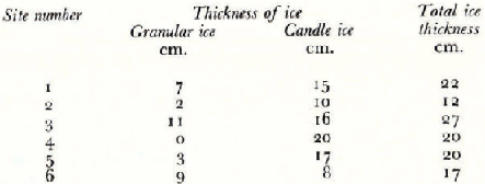
Ice samples were obtained at 6 sites (Fig. 26). At all sites except site 5 the ice is granular in the surface layer with candle ice below it. Examples of this structure are shown in Figures 27 to 29. In Figures 27 and 29 are shown horizontal sections of ice from the surface and the bottom respectively, and a vertical section from the bottom is shown in Figure 28. The ice from the surface layer is granular (Figs. 27 and 28) and the appearance of the vertical and horizontal sections is similar. Granular ice in the surface layer is a common structure of lake ice; it is formed by the freezing of deposited snow soaked in water. This kind of structure was not found in the ice at Peters Lake and this fact shows that the water level of the lake did not increase after the formation of the ice. The change in water level at Lake Nukabira would be considerable. The thickness of ice at different sites is summarized in Table I.

Fig. 27. Horizontal section of granular ice in the surface layer of ice at site 2; under crossed polaroids

Fig. 28. Vertical section of ice at site 2 showing granular and candle ice; under crossed polaroids

Fig. 29. Horizontal section of ice with horizontal c-axes at the bottom of the ice at site 2. Numerous short bars show Tyndall figures; under crossed polaroids
The c-axis orientation was determined by the same procedure as described already. At sites 1 and 2 all the candle ice showed predominantly horizontal c-axes and its grain-size was quite small. The numerous short bars which can be seen in Figure 29 characterize the ice with horizontal c-axes at site 2. Figure 30 shows the carbon rubbing from an etched ice surface, proving the presence of ice with horizontal c-axes at site 1 and the increase of grain-size with ice depth. Ice with vertical c-axes at site 5 is shown in the rubbing of Figure 31. Numerous short horizontal bars seen in the vertical section in Figure 31 are the marks of Tyndall figures. The many hexagonal figures seen in the horizontal section in Figure 31 are also the marks of Tyndall figures. Comparing these two sections, one sees that the orientation of the c-axes of the crystals in Figure 31 is perfectly vertical. The c-axis vertical ice was found not only at site 5, but also at sites 3, 4 and 6.

Fig. 30. Carbon rubbings of vertical and horizontal sections of ice with horizontal c-axes at Site 1, Lake Nukabira, showing grain boundaries, Tyndall figures and increase in grain-size with depth

Fig. 31. Carbon rubbings of vertical and horizontal sections of ice with vertical c-axes at site 5. Lake Nukabira, showing grain boundaries and Tyndall figures. Horizontal section was taken at the bottom of the ice
The statistical distribution of horizontal and vertical c-axes at four different sites is shown in Figure 32. The ice from the bay has predominantly horizontal c-axes, while the ice with predominantly vertical c-axes occurs in the main part of the lake. It was considered that wind action was responsible for the formation of the two types of ice. The grain-size of vertical c-axis ice was much larger than that of the horizontal c-axis ice, as can be seen by comparing Figure 30 with Figure 31.

Fig. 32. Histograms of the c-axis orientation at four different sites
(c) Impurity measurement
The same procedure as described previously for the measurement of impurity was followed. Since the ice thickness was not great enough to enable separation into two layers in preparing the samples for measurement, relationship between grain-size and impurity content at any one site could not be examined. It was expected, however, that the difference in grain-size depending upon both the location of the sampling site and the types of ice would result in some difference in impurity content.
Typical results are shown in Figure 33. A peak in the curve is clearly observable for the fine-grained crystals at site 2 but not for coarse-grained crystals at site 3. As was described in detail previously, a peak appeared between the third and sixth sequence numbers. This shows clearly the impurity from boundaries. The curve for site 3 shows the same features as that of the ice from Peters Lake.

Fig. 33. Change of specific electrical conductivity in an ice sample, using the ice samples from sites 2 and 3
Discussion
(a) Ice structure
The present investigation supports the idea proposed by Reference KnightKnight (1962) explaining the causes of two types of ice, i.e. that wind is the main factor. The fact that the ice structure at Peters Lake in 1962 was quite different from that in 1961 (Reference KnightKnight, 1962) and in 1959 (Reference Barnes and BushnellBarnes, 1959) suggests the great difference in weather conditions at an early stage in the freezing of the lake water. The uniform ice structure at Peters Lake suggests that break-up of the initial ice skim did not take place during that period, i.e. wind was very slight.
The difference in grain-size in the surface layer and the c-axis orientation would depend upon the weather conditions during an early stage in the freezing of lake water. If lake water is frozen on a very calm day and under slight temperature gradient conditions, and the initial ice skim does not break up, the ice would start with vertical c-axes and show coarse grain. The vertical c-axis ice with coarse grain observed in the main area of Lake Nukabira would not belong to this category. Though wind conditions were much calmer in the bay of Lake Nukabira than in the main area of the lake, the ice in the bay had horizontal c-axes and was fine-grained.
The break-up of the initial ice skim is considered to be an important factor in the formation of the two types of ice (vertical c-axis ice and horizontal c-axis ice). Wind-broken initial ice skim would push pieces of broken ice towards a coast, and the ice would become jammed. Reference Lyons and StoiberLyons and Stoiber (1962) have pointed out that the thickness of the supercooled water layer and the greater velocity of crystallization in the basal plane of the ice are among the factors influencing preferred orientation of the c-axis. Under normal weather conditions the orientation of c-axes in most types of lake ice would be predominantly horizontal as is noted in the ice of Peters and Nukabira Lakes. Pieces of broken ice slabs, pushed towards a coast by the wind, would be jammed just like a pack of cards in a horizontal direction. Thus, initial c-axis horizontal ice could become the c-axis vertical ice in the area of jammed ice, mostly occupying a shore zone.
(b) Decay of snow and ice at Peters Lake
Minute efflorescences of rock particles were observed on and in the deposited snow on the lake (Fig. 34). They were naturally wind-blown particles and distributed over almost the whole central area of the lake between the east and west shores. A large number of particles was observed at the southern end of the lake. The maximum quantity of particles measured was about 0.05 g./cm.3 in area “C” and 0.02 g./cm.3 in area “D” of Figure 5.

Fig. 34. Naturally wind-blown rock particles observed on and in redeposited snow at Peters Lake
From the artificial acceleration of snow melting by scattering soil particles on a snow surface (Reference Magono and KumaiMagono and Kumai, 1954) it is known that a very small amount of soil is enough to accelerate melting. A quantity of 0.01 g./cm.3 can double the rate of melting. If such a small quantity of soil particles could double the rate of melting, the rock particles observed at Peters Lake must considerably accelerate the decay of snow and ice.
Taking into account the differences in ice thickness and the distribution of rock particles over the whole area of Peters Lake, it is considered that the ice along the east shore area of the lake north of the camp (area “B” in Figure 5) would be stronger and last longer than the ice in other areas of the lake.
Acknowledgements
The field investigation reported in this paper was supported by the Arctic Institute of North America under contract with the Geophysics Research Directorate, Air Force Cambridge Research Laboratories. Professor Ukichiro Nakaya directed the research project, but in April 1962 while the authors were in Alaska he unfortunately died. The authors wish to express their sincere sorrow over Professor Nakaya’s death and their grateful thanks to him for guidance in planning the work. We are indebted to Dr. Max C. Brewer, Director of the Arctic Research Laboratory at Point Barrow, for kindly arranging the research programme and to Mr. R. F. Riddell for his valuable assistance in managing the camp at Peters Lake. Indebtedness is acknowledged to Dr. A. Higashi for his direction of this project after Professor Nakaya’s death and for his criticism during preparation of the manuscript.


