


1. Introduction
Vision-based kinematic parameter estimations are generally termed as very accurate due to the non-cumulative in joint errors. The programming of very high precision using the traditional method like “teach-in” is very expensive. So, the need for offline programming is in demand and proves to be very accurate as it comprises minor pose errors. The role of this paper is to increase the accuracy of the parallel robot, that is the architecture consists of three Delta robots in a symmetric order using the vision-based calibration. In this paper, the central part describes the calibration of the parallel robots based on the Delta architecture. The Delta robots have three degrees of freedom (DOF), only translation along the x, y and z axes.
Sheng-Weng [Reference Shih, Hung and Lin1] proposes kinematic parameter identification for an active binocular head. The configuration of the binocular head comprises four revolute joints and two prismatic joints. The kinematic parameter of the binocular head is unknown due to the presence of the off-the-shelf components. It estimates the kinematic parameter without any initial estimates. Therefore, existing solutions of closed-form based on pose measurements do not provide the required accuracy. As a result, the design of a new technique does not need measurements of orientation. Only the position measurements of calibration are necessary to obtain the highly accurate estimates in the closed-form systems. This method applies to the identification of kinematic parameter problems. In this case, the links are rigid; joints are either prismatic or revolute.
Zubair et al. [Reference Zubair, Mathew, Mukherjee and Gupta2] have explained computer vision technology to analyse the Stewart platform forward kinematics using a vision sensor. The unique solution of the kinematics of the platform, a predefined library of ArUco markers, has been used for pose estimation. The analytical solution for the kinematics problem of a Stewart platform mathematically has multiple solutions and is nonlinear. By using computer vision, complexity decreases and speed increases. The advantage of using ArUco markers is that a single marker has enough information for pose estimation [Reference Jurado, Salinas, Madrid and Marn3]. Multiple such ArUco markers are used to increase pose accuracy further, and the pose of the entire board of multiple markers provides us with reliable pose estimation. The camera used is the Logitech C270 with a sensor resolution of 1280 × 960.
Garrido et al. [Reference Jurado, Salinas, Madrid and Marn3] present a fiducial marker for the camera pose estimation and have applications like tracking, robot localization, augmented reality, etc. The derivation of inter-marker distance to its maximum attained by the binary markers was also performed. Detection of the markers in an automated fashion is also presented. A solution to the occlusion problem in the augmented reality is presented. This noise propagated in the estimation of the camera extrinsic parameters. The jitter level observed for the black and white marker is less than that of the green and blue ones. Analysis of the occlusion is also presented here.
Garrido-Jurado [Reference Jurado, Salinas, Madrid and Medina4] presented square-based fiducial markers, that is very efficient for the camera pose estimation. To maximize the error correction capabilities, the inner binary codification with a significant inter-marker distance is implemented. Mixed Integer Linear Programming approach generates the fiducial markers dictionaries (square shape) to maximize their inter-market distance. The primary method finds the optimal solution for the small dictionaries and bits as the computing time is too long. The secondary way is a formulation to extract the sub-optimal dictionaries having time constraints.
Yuzhe [Reference Liu, Wu, Wang and Wang5] presented kinematic parameter identification and calibration algorithm in parallel manipulators. Comparison with the other two conventional techniques is also presented. Investigation of the mathematical properties of the identification technique is demonstrated by analysing the identification matrix using the singular value decomposition. The identification of simulation parameters is implemented based on both six-degree-of-freedom (DOF) and five-degree-of-freedom measurements, respectively.
Reymong [Reference Vischer and Clavel6] kinematic calibration of the Delta robot is discussed. The kinematic calibration of the two models has been introduced. The first model took care of all mechanical parts except the spherical joints and was termed “model 54.” The second model considers only that deviation that affects the end-effector position, not its orientation, and is termed as “model24.” An experimental setup is presented to estimate the end-effector pose with respect to the fixed base frame. The kinematic parameter estimation is performed after the estimation of the pose of the end effector.
Aamir [Reference Hayat, Chittawadigi, Udai and Saha7] discussed serial robot kinematic identification. This area is an active domain of research to improve robot accuracy. The Denavit–Hartenberg (D-H) parameters represented the architecture of the robot and provided by its manufacturer. Due to time, these parameters are given by the manufacturer change, so it needs to be identified. An analytical technique is discussed for the identification of a serial industrial robot. This can be achieved by providing the motion to one joint and keeping all rest joints to fix. From this, the point values on the robot’s end effector were estimated using the singular value decomposition method.
Hoai [Reference Nguyen, Zhou and Kang8] presented robot kinematic identification errors during the calibration process. This requires accurate pose (orientation and position) measurements of end effector (acting robot) in Cartesian space. A method is proposed for the pose measurement of end-effector calibration. This method works on the feature extraction for the set of target points placed on the robot end effector. The measurement validation is done by simulation results serial robot (PUMA) using the proposed method. The experimental results and calibration results are validated using the Hyundai HA-06 robot. This proves the correctness and reliability of the proposed technique. This technique can also be deployed to the robots with only revolute joints or the last joint as revolute.
Shi Baek [Reference Park and Kim9] proposes the dynamics modelling implementation and the interfacing with the hardware of a Delta parallel manipulator. This architecture is complex, and the derivation of the inverse dynamics is performed using the Lagrangian equations (first type). As another Delta robot that is commercially available can attain a speed of 10 m/s. Fast and accurate dynamics computation is essential for high-speed applications like intelligent conveyor systems and the manufacturing industry to compute the torque for controlling the Delta manipulator. The validation of the inverse dynamics with the ADAMS is also performed, and less than 0.04 millisecond time is needed for calculating the dynamics and inverse kinematics module.
Modelling of the generic error is presented in Ruibo [Reference He, Zao, Yang and Yang10] and is based on the exponentials (POEs) used for the calibration of the serial robot. So, the parameters that are identifiable of the given model were analysed. The result of the analysis shows that errors in joint twists are identifiable. The second outcome is the zero position error of joint, and the transformation error at initial is not identified provided the same error model. When the joint twists coordinates are linearly independent, errors in joint (zero position) are identifiable. As for the n degree of freedom (DOF) robot, the maximum identifiable parameters are (6n + 6). If n(r) is termed as number of revolute joints, n(t) is termed as prismatic joint then maximum identifiable parameters represented as (6n(r) + 3n(t) + 6). The error model’s POE expression can be a minimal, complete and continuous serial-robot calibration for kinematic modelling.
Dynamic parameter identification presented in Vishaal [11] of an industrial robot-like KUKA KR5 is discussed. KUKA KR5 has six revolute joints and comprises a serial architecture. As for this, a simplified model of the serial robot is considered, that is those joints, which performs orthogonal to the gravity vector. Euler–Lagrangian technique is used to formulate the dynamic model and then find the dynamic parameters. Thus, yielding the equation of the motion linearization is performed and expressed in the terminology of base parameters. The estimation of the base parameters is calculated by the technique called linear regression, as applied to the given planar trajectory points. KUKA KRC2 controller has a sensory interface called robot sensory interface, used to acquire the torque at each joint and the end-effector pose of the serial robot. The results obtained, that is dynamic parameters, validated with the numerical values of the mass moment computed from the curve fitting approach.
Aamir [Reference Abhishek, Hayat, Udai and Saha12] presented the estimation of the dynamic parameters of the serial robot, and a comparison with the CAD model is performed. The identification equation of the serial robot is inherited from the Newton-Euler technique, that is geometric parameters and joint values as input and joint torque data as output. The dynamic parameters are identified for the CAD model provided by the robot manufacturer in simulation. Experimentally, seven DOF robot KUKA-iiwa R800 is used. The variation between the joint torques predicted from the estimated base parameters obtained using the CAD model and actual robot is presented. The factors responsible for the variation are also highlighted. A detailed study of Delta robot structure, kinematics, Delta catching system, selection of catching system, design of components, dynamics analysis of the system, control analysis has been studied.
Boney [Reference Bonev13] has explained the success story of the Delta parallel robot. Robots are achieving acceleration up to 50 g in experiments and 12 g in industrial use. Delta robot is perfect for application where the light object has to be placed from one place to another (10 g–1 kg). Murray [Reference Zsombor-Murray14] has discussed the kinematic analysis of the Delta robot (Clavel’s) by the geometric method. The geometric configuration of Clavel’s Delta manipulator is explained in detail. The initial conceptual design has been taken from Clavel’s Delta configuration.
Tsai [Reference Tsai15] has discussed the position analysis of the University of Maryland manipulator. The graphical and algebraic solutions for direct and inverse kinematic analysis of manipulators have been explained. Codourey [Reference Codourey16] has presented the dynamic modelling of the parallel robot for computed torque control implementation. The number of forces and motion of the end effector is significantly less in the concept of micromanipulation. Laribi [Reference Laribi, Romdhane and Zeghloul17] has explained the dimensional analysis of the Delta robot for a specified workspace, that is designs of the dimensional configuration of the Delta manipulator for a given workspace. Kosinska [Reference Kosinska, Galicki and Kedzior18] has explained the optimization of variables of the Delta parallel manipulator for a workspace. The methodology of deriving design constraints from the closed-loop configuration of the Delta-4 parallel manipulator is given. The initial conceptual design has been taken from Clavel’s Delta configuration. Tsai [Reference Tsai19] has explained the methodology based on the principle of virtual work for static analysis of parallel manipulators. The torque transmitted at the actuated joints due to the grasping force at the end effector and, finally, the Jacobian formulation has been used.
2. Robots for catching
Through the years, researchers and engineers have developed various catching-based robots. Major catching-based robotic systems were developed in the mid-1990s and 2000s. Philip W. Smith et al. [Reference Philip, Nandhakumar and Ramadorai20] proposed vision-based robust robotic manipulation algorithms used for objects having non-rigid in nature. It is based on an image-based representation of the non-rigid structure and relative elasticity, with no a priori physical model. The relative elasticity has many advantages as simplicity, comprehensiveness and generality. This method overcomes many limitations of existed non-rigid object manipulation.
Satoshi Yonemoto et al. [Reference Yonemoto and Taniguchi21] proposed mapping real-time human action with its corresponding virtual environment. In this approach, the scene constraints fall between the user motion and the virtual object. This approach has resulted in the action information and non-trivial to have the body posture representation. Yejun Wei et al. [Reference Wei and Goodwine22] described non-smooth domains and demonstrated and verified a motion planning algorithm for the system. In this approach, catching is performed on a non-smooth object using four fingers. Park et al. [Reference Park and Ayanna23] described a method that takes the visual data to produce force guidance data and an applicable tele-manipulative system. Mkhitaryan et al. [Reference Mkhitaryan and Burschka24] presented a vision-based haptic multisensory. The system interacts with objects having fragile nature. Chen et al. [Reference Chen, Zhang, Zhang and Kwok25] revealed the significance of active lighting control in the domain of robotic manipulation.
In this paper, various strategies of intelligent lighting control for industrial automation and robot vision tasks are discussed. However, none of the manipulations of an object by the direct drive parallels the Delta robotic system (one Delta end effector as one finger, i.e. three-fingered parallel robot) applied before. In section A, the proposed methodology has been discussed. Section B discusses some geometry background. Section C describes the initial conceptual design, and section D discusses the mechanical structure design. In Section 2, kinematic analysis and experimental setup used are discussed. In section 3, controller design, including the PID, genetic algorithm and current limiting, is discussed. In section 4, catching the object is examined. Results and validation are discussed in section 5.
2.1. Experimental setup
As shown in Fig. 1, three parallel robots are arranged in symmetric order in the kinematic identification experimental setup. This paper is limited to the kinematic and parameter estimation of the system to perform the catching of the object (cube) in 3D as it moves dynamically. Validating the proposed approach with the standard estimation techniques like the iterative least square method is performed. The experimental setup comprises three Delta robots, and each of the end effectors behaves like one finger, so it comprises three fingers that perform the catching and manipulation in the real-time scenario. The pose of the moving platform is estimated using a pre-calibrated vision sensor (Basler scout)
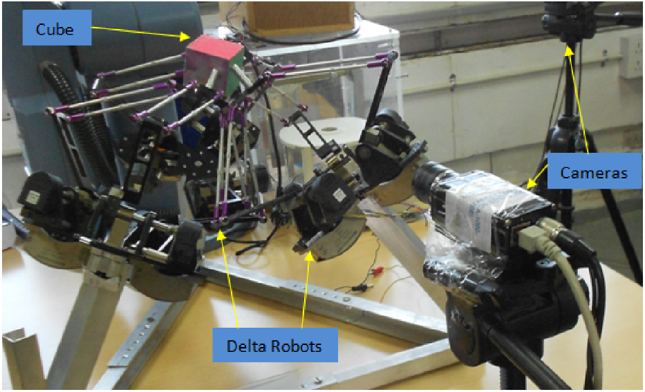
Figure 1. Vision-based kinematic identification experimental setup [Reference Sachin, Sudipt and o39–Reference Sachin and Sudipto41].
The finger as Delta end effector is used in this architecture for high payload and dedicated to high-speed applications like catching (shown in Algorithm 1). In this architecture, the moving frame has no rotation with respect to the fixed frame, that is 3DOF of only translation in X, Y, Z axis, as shown in Fig. 2.
Algorithm 1 Extracting the pose of the manipulating object [cube], that is three translations and three rotations, is 6-DOF with respect to the fixed base coordinates system using the camera as a vision sensor. After that, inverse kinematics of all three Delta robots is performed, estimating the thetas [ $\theta$
1 to
$\theta$
1 to $\theta$
9] from all the three Delta robots, and feeding the calculated thetas to the controller of the manipulating system is performed. Getting feedback from the encoder and PID control scheme is also implemented. The tuning of the PID values is achieved at every cycle using the optimizing technique. Validation of the kinematic analysis and identification results with the experimental setup is also achieved.
$\theta$
9] from all the three Delta robots, and feeding the calculated thetas to the controller of the manipulating system is performed. Getting feedback from the encoder and PID control scheme is also implemented. The tuning of the PID values is achieved at every cycle using the optimizing technique. Validation of the kinematic analysis and identification results with the experimental setup is also achieved.

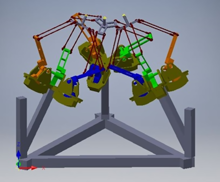
Figure 2. Three Delta combined system architecture.
The use of parallelograms is the basic design of the Delta robot. This design allows an identical rotation matrix ( R = I 3 × 3 ) between the static and moving platform. The three parallelograms control the orientation of the unfixed platform, which remains with 3DOF translation, as shown in Fig. 2. The input links of the three parallelograms are mounted on rotating levers via revolute joints. Link dimensions have been appropriated with reference to Clavel’s configuration. The base three arms (upper arms) are connected with three parallelograms (lower Arm). The ends of the lower Arm are connected to a small triangular moving platform. Actuation of the input links moves the triangular platform in three dimensional, that is X p , Y p , and Z p direction.
Delta manipulator employs revolute joints and spherical joints to give platform output to translational motion. The conceptual design and configuration have been understood [Reference Shinno, Yoshioka and Sawano26]. In Fig. 3, link 0 is labelled as a fixed base and link 16 as a moving platform. The lower Arm is labelled as links 1, 2, 3. The upper arms are made up of a four parallelogram (link 4, 7, 10 & 13 for the first limb; 5, 8, 11 & 14 for the second limb, and 6, 9, 12 & 15 for the third limb). Three parallel joints attach the upper arms, lower arms and the two surfaces at points A, B and C, and each parallelogram has four revolute joints. Overall, there are 17 links and 21 revolute joints.

Figure 3. Mechanical structure of individual manipulator.
The joints are redundant and have 3DOF translation. Due to the four-bar parallelogram and the three revolute joints at points A, B and C, the limb constrains the unfixed surface from rotating about the z and x axis. The two limbs constrain the unfixed surface from rotating about any axis, and thus, the system has three DOF. This feature is helpful in x-y-z positioning devices.
The schematic of the Delta manipulator used in this paper is shown in Fig. 4. The angles defined as $\boldsymbol\theta$
1i
,
$\boldsymbol\theta$
1i
, $\boldsymbol\theta$
2i,
$\boldsymbol\theta$
2i, $\boldsymbol\theta$
3i
;
$\boldsymbol\theta$
3i
; $\boldsymbol\theta$
1i
are the angles of the Ist link with respect to the horizontal.
$\boldsymbol\theta$
1i
are the angles of the Ist link with respect to the horizontal. $\boldsymbol\theta$
2i
is the angle between l2i and the extension of l
1i
.
$\boldsymbol\theta$
2i
is the angle between l2i and the extension of l
1i
. $\boldsymbol\theta$
3i
is the angle between the second link and its projection on the x-z plane.
$\boldsymbol\theta$
3i
is the angle between the second link and its projection on the x-z plane.
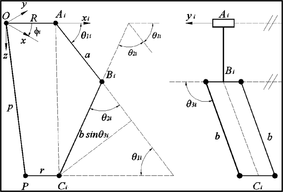
Figure 4. Schematic diagram of parallel mechanism.
In the Delta robot architecture, two spherical joints si1, si2, and a revolute joint bi. The angle between axes X, u 1 , v 1 is 120°, and the direction of axes Z, w 1 and w 2 are the same.
3. Kinematic analysis
The three DOF Delta robot is capable of 3D transitional of its moving surface. As in the proposed Delta architecture, there are three identical Revolute-Universal-Universal (R-U-U) chains as legs. In the figure shown below, points B
i
, i = 1,2,3 represent the hips, points, P
i
, i = 1,2,3 are the ankles and points, A
i
, i = 1,2,3 represents the knees. The length of the triangle, which is equilateral, and the base is s
B, and the length of the equilateral triangle in the moving platform is s
P
. The moving platform is above the fixed platform in our proposed Delta architecture, as shown in Fig. 5. There is no rotation between the moving platform and the base platform. That is, (
R
3 × 3
is the identity matrix). Thus, only the translational vector between the moving and the fixed platform is to be considered. “B” is the fixed Cartesian reference frame. The origin is situated at the centre of the bottom triangle. “P” is not a fixed Cartesian reference frame. The origin is situated in the centre of the platform triangle. The rotation matrix $\begin{array}{*{20}{c}}{\textbf{B}}\\{\textbf{P}}\end{array}R$
=
I
3 × 3
is constant as orientations of P and B are the same. The joint variables are
$\begin{array}{*{20}{c}}{\textbf{B}}\\{\textbf{P}}\end{array}R$
=
I
3 × 3
is constant as orientations of P and B are the same. The joint variables are $\boldsymbol\theta$
= {
$\boldsymbol\theta$
= { $\boldsymbol\theta$
1
,
$\boldsymbol\theta$
1
, $\boldsymbol\theta$
2
,
$\boldsymbol\theta$
2
, $\boldsymbol\theta$
3
}
T
, and the Cartesian parameters are
$\boldsymbol\theta$
3
}
T
, and the Cartesian parameters are $\begin{array}{*{20}{c}}{\textbf{B}}\\{\textbf{P}}\end{array}R$
= {x y z}
T
. The three upper legs of lengths “L” and three lower legs of lengths “l” have high symmetry.
$\begin{array}{*{20}{c}}{\textbf{B}}\\{\textbf{P}}\end{array}R$
= {x y z}
T
. The three upper legs of lengths “L” and three lower legs of lengths “l” have high symmetry.
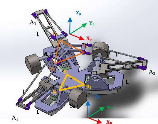
Figure 5. Delta Robot kinematic representation.
3.1. Forward position kinematics [simulation]
The forward position kinematics is defined as the three actuated joint angles $\boldsymbol\theta$
= {
$\boldsymbol\theta$
= { $\boldsymbol\theta$
1
,
$\boldsymbol\theta$
1
, $\boldsymbol\theta$
2
,
$\boldsymbol\theta$
2
, $\boldsymbol\theta$
3
}T are given then compute the resulting Cartesian position of the unfixed surface control point (P),
$\boldsymbol\theta$
3
}T are given then compute the resulting Cartesian position of the unfixed surface control point (P), $\begin{array}{*{20}{c}}{\textbf{B}}\\{\textbf{P}}\end{array}\textbf{R}$
= {x y z}
T
. The forward position kinematics solution for parallel robots is non-trivial.
$\begin{array}{*{20}{c}}{\textbf{B}}\\{\textbf{P}}\end{array}\textbf{R}$
= {x y z}
T
. The forward position kinematics solution for parallel robots is non-trivial.
The correct solution set is selected for a straightforward analytical solution, as there is translation-only motion in the 3DOF Delta robot, as shown in Fig. 6. Given $\boldsymbol\theta = {\left\{ {{{\boldsymbol{\theta }}_1}{{\boldsymbol{\theta }}_2}{{\boldsymbol{\theta }}_3}} \right\}^T}$
, then compute the three absolute vector knee points using
$\boldsymbol\theta = {\left\{ {{{\boldsymbol{\theta }}_1}{{\boldsymbol{\theta }}_2}{{\boldsymbol{\theta }}_3}} \right\}^T}$
, then compute the three absolute vector knee points using $\begin{array}{*{20}{c}}{\textbf{B}}\\ \textbf{i}\end{array}{\textbf{A}} = \begin{array}{c}{\textbf{B}}\\ \textbf{i}\end{array}{\textbf{B}} + \begin{array}{*{20}{c}}{\textbf{B}}\\ \textbf{i}\end{array}{\textbf{L}};i=1,2,3$
. As the unfixed surface of the Delta robot orientation is constant and horizontal with [
$\begin{array}{*{20}{c}}{\textbf{B}}\\ \textbf{i}\end{array}{\textbf{A}} = \begin{array}{c}{\textbf{B}}\\ \textbf{i}\end{array}{\textbf{B}} + \begin{array}{*{20}{c}}{\textbf{B}}\\ \textbf{i}\end{array}{\textbf{L}};i=1,2,3$
. As the unfixed surface of the Delta robot orientation is constant and horizontal with [ $\begin{array}{*{20}{c}}{\textbf{B}}\\ \textbf{i}\end{array}{\textbf{A}}\left] = \right[{\textbf{I}_{\textbf{3}{\textbf{x}}\textbf{3}}}]$
; therefore, all the virtual sphere centres (three in numbers) are
$\begin{array}{*{20}{c}}{\textbf{B}}\\ \textbf{i}\end{array}{\textbf{A}}\left] = \right[{\textbf{I}_{\textbf{3}{\textbf{x}}\textbf{3}}}]$
; therefore, all the virtual sphere centres (three in numbers) are $\begin{array}{*{20}{c}}{\textbf{B}}\\{{\textbf{iv}}}\end{array}{\textbf{A}} = \begin{array}{*{20}{c}}{\textbf{B}}\\ \textbf{i}\end{array}{\textbf{A}} - \begin{array}{*{20}{c}}{\textbf{p}}\\ \textbf{i}\end{array}{\textbf{P}};i=1,2,3$
.
$\begin{array}{*{20}{c}}{\textbf{B}}\\{{\textbf{iv}}}\end{array}{\textbf{A}} = \begin{array}{*{20}{c}}{\textbf{B}}\\ \textbf{i}\end{array}{\textbf{A}} - \begin{array}{*{20}{c}}{\textbf{p}}\\ \textbf{i}\end{array}{\textbf{P}};i=1,2,3$
.
 \begin{equation*}{}_{1{\textrm{v}}}^{\textrm{B}}{\textrm{A}} = \left\{ {\begin{array}{*{20}{c}}0\\[3pt] { - {w_B} - {\textrm{L}}cos{\theta _1} + {u_p}}\\[3pt] { - {\textrm{L}}sin{\theta _1}}\end{array}} \right\}\end{equation*}
 \begin{equation*}{}_{2{\textrm{v}}}^{\textrm{B}}{\textrm{A}} = \left\{ {\begin{array}{*{20}{c}}{\dfrac{{\sqrt 3 }}{2}\left( {{w_B} + {\textrm{L}}cos{\theta _2}} \right) - \dfrac{{{s_p}}}{2}}\\ \\[-7pt] {\dfrac{1}{2}\left( {{w_B} + {\textrm{L}}cos{\theta _2}} \right) - {w_p}}\\ \\[-7pt] { - {\textrm{L}}sin{\theta _2}}\end{array}} \right\}\end{equation*}
 \begin{equation*}{}_{3{\textrm{v}}}^{\textrm{B}}{\textrm{A}} = \left\{ {\begin{array}{*{20}{c}}{ - \dfrac{{\sqrt 3 }}{2}\left( {{w_B} + {\textrm{L}}cos{\theta _3}} \right) + \dfrac{{{s_p}}}{2}}\\ \\[-7pt] {\dfrac{1}{2}\left( {{w_B} + {\textrm{L}}cos{\theta _3}} \right) - {w_p}}\\ \\[-7pt] { - {\textrm{L}}sin{\theta _3}}\end{array}} \right\}\end{equation*}
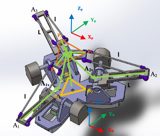
Figure 6. Delta robot forward position kinematics diagram.
Delta robot forward position kinematics is determined by its point of intersection of the three spheres. This sphere is represented by a centre point termed as c and the scalar radius defined by r.
In this section, the analytical solution is computed as the intersection point of the given three spheres. In this concern, we need to solve a transcendental equation that is coupled in nature. So, to solve the forward kinematics solution, there exists an intersection-three-sphere algorithm. If this is the case when the entire three-sphere centres { $\begin{array}{*{20}{c}}{\textbf{B}}\\{{\textbf{iv}}}\end{array}{\textbf{A}}$
} have the same height (Z), then the solution will be in the zone of the algorithmic singularity. To fix the problem of rotating the coordinates, that is all {
$\begin{array}{*{20}{c}}{\textbf{B}}\\{{\textbf{iv}}}\end{array}{\textbf{A}}$
} have the same height (Z), then the solution will be in the zone of the algorithmic singularity. To fix the problem of rotating the coordinates, that is all { $\begin{array}{*{20}{c}}{\textbf{B}}\\{{\textbf{iv}}}\end{array}{\textbf{A}}$
}, height values are not the same.
$\begin{array}{*{20}{c}}{\textbf{B}}\\{{\textbf{iv}}}\end{array}{\textbf{A}}$
}, height values are not the same.
In this problem, two solutions are encountered when the three spheres are intersected. If the sphere meets tangential, then it results in one solution. If the centre distance is too great for the given sphere radii, then it has zero solution. The second case is the case when there is an imaginary solution, and the data are inconsistent. The algorithm (spheres-intersection) computes solution sets, and the computer automatically chooses the solution below the base triangle. This approach to the forward position kinematics for the Delta robot estimated results same as of solving the kinematics equations, depicted as
 \begin{equation*}\begin{array}{*{20}{c}}\textbf{B}\\\textbf{P}\end{array}\textbf{R}=\{\textbf{x}\ \textbf{y}\ \textbf{z}\}^{T}\ \textrm{given}\ \boldsymbol\theta=\{\boldsymbol\theta_{\textbf{1}}, \boldsymbol\theta_{\textbf{2}}, \boldsymbol\theta_{\textbf{3}}\}^{T}. \end{equation*}
3.2. Forward position kinematics using vision sensor [experimental]
In computer vision terminology, the object’s pose is defined as the relative orientation and position of an object coordinate system with respect to the camera coordinates system. The object’s pose is estimated, so the need for at least 3 points on the 3D object in the world frame (U V W) is required as the task is to infer the coordinates of the 3D points in the camera frame from the 2D coordinates of the image (x, y).
In the library called ArUco, which consists of the board having multiple markers is used. The points of interest in the board are the four corners of each marker and are known to be in a plane and with known separation. This is compared to the image points projected back from the camera. Direct Linear Transformation is used for the initial estimate for [ R , t ], and later on, refinement is done using the Levenberg–Marquardt (LMA) method. The re-projection error, the sum of the squares distances between the observed projections and the projected object points, is minimized using the LMA method. Thus, the method is also called the least squared method. By using the pose of the moving platform with respect to the camera and stationary base with respect to the camera, the orientation and position of the moving platform can be computed with respect to the base using:
 \begin{equation*}{{\textbf{H}}_{\textbf{B}}^{\textbf{P}}} = {\left[ {{\textbf{H}}_{\textbf{C}}^{\textbf{B}}} \right]^{ - \textbf{1}}}{\textrm{*}}{{\textbf{H}}_{\textbf{C}}^{\textbf{P}}}\end{equation*}
where ${{\textbf{H}}_{\textbf{B}}^{\textbf{P}}}$
is the homogeneous transformation matrix of the platform with respect to the base frame.
${{\textbf{H}}_{\textbf{B}}^{\textbf{P}}}$
is the homogeneous transformation matrix of the platform with respect to the base frame. ${{\textbf{H}}_{\textbf{C}}^{\textbf{B}}}$
is the homogeneous transformation matrix of the base platform with respect to the camera.
${{\textbf{H}}_{\textbf{C}}^{\textbf{B}}}$
is the homogeneous transformation matrix of the base platform with respect to the camera. ${\textbf{H}}_{\textbf{C}}^{\textbf{P}}$
is the homogeneous transformation matrix of the moving platform with respect to the camera.
${\textbf{H}}_{\textbf{C}}^{\textbf{P}}$
is the homogeneous transformation matrix of the moving platform with respect to the camera.
We can estimate these matrices using a board of 16 markers, evenly spaced in a 4 × 4 grid, placed on the base and the moving platform. The board for the base and moving platform is separated, and the markers are of different sizes. The size of the markers on the platform is of side 26 mm, and the markers on the base are of side length 40 mm. Different sizes are chosen so that the edges of the markers can be detected accurately on both the base and the platform without having to move the camera. The centre of the boards is placed to coincide with the origins of the base and the platform coordinate systems. ${\textbf{T}}_{\textbf{B}}^{\textbf{P}}$
and
${\textbf{T}}_{\textbf{B}}^{\textbf{P}}$
and ${\textbf{R}}_{\textbf{B}}^{\textbf{P}}$
are extracted from the homogeneous transformation matrix ArUco markers and are preferred over similar marker dictionaries such as ARTag or AR Toolkit because the waymarkers are added into the marker dictionary. After dictionary creation, the minimum hamming distance between a marker in the dictionary with itself and other markers is
${\textbf{R}}_{\textbf{B}}^{\textbf{P}}$
are extracted from the homogeneous transformation matrix ArUco markers and are preferred over similar marker dictionaries such as ARTag or AR Toolkit because the waymarkers are added into the marker dictionary. After dictionary creation, the minimum hamming distance between a marker in the dictionary with itself and other markers is $\hat{\boldsymbol\tau}$
. The error correction capabilities of an ArUco dictionary are related to
$\hat{\boldsymbol\tau}$
. The error correction capabilities of an ArUco dictionary are related to $\hat{\tau}$
. Compared to AR Toolkit (cannot correct bits) and AR Tag (can correct up to 2 bits only), ArUco can correct up to [
$\hat{\tau}$
. Compared to AR Toolkit (cannot correct bits) and AR Tag (can correct up to 2 bits only), ArUco can correct up to [ $\hat{\boldsymbol\tau}-12$
] bits. If the distance between the erroneous marker and a dictionary marker is less than or equal to [
$\hat{\boldsymbol\tau}-12$
] bits. If the distance between the erroneous marker and a dictionary marker is less than or equal to [ $\hat{\boldsymbol\tau}-12$
], the nearest marker is considered the correct marker.
$\hat{\boldsymbol\tau}-12$
], the nearest marker is considered the correct marker.
The output from the marker detection code of ArUco is the form of the position vector of the centre of the marker and the Rodrigues vector of the marker frame. The Rodrigues vector is converted into a 3 × 3 rotation matrix. The following are the experimental iterations.
-
1. Single marker pose detection using translation and rotation matrix.
-
2. Marker pose detection using only translational information from the three markers.
-
3. Pose estimation using a board with multiple evenly spaced markers.
Single marker detection resulted in a very stable translation vector but an unstable rotation matrix. The values showed unacceptable variation for a stationary platform and camera position. Even if the input is an image instead of a video stream, the rotation matrix is unreliable. Therefore, a single ArUco marker is insufficient to estimate the pose of a Delta platform accurately. The following three ArUco markers arranged at the corners of an equilateral triangle of 100 mm are used to extract plane information solely from the position vectors of the three markers. The results are more reliable than single marker detection. While repositioning the markers in the same plane, the plane equation derived from the pose estimation of the 3-marker system showed variation reaching 5o.
A solution adopted for improving pose estimation is increasing the number of markers in the form of a board and extracting the board’s pose as a whole instead of individual markers. On repositioning this arrangement in the same plane, the orientation vector of the board showed a slight deviation limited to a maximum error of around 1o, as shown in Fig. 7.

Figure 7. Experimental setup for Pose estimation.
Kinematic analysis of the Delta platform is attempted using marker board detection for pose estimation. A board of 16 markers, evenly spaced in a 4 × 4 grid, is placed on the base and the moving platform. The board for the base and moving platform is separated, and the markers are of different sizes. The size of the markers on the platform is of side 26 mm, and the markers on the base are of side length 40 mm. Different sizes are chosen so that the edges of the markers can be detected accurately on both the base and the platform without having to move the camera. The centre of the boards is placed to coincide with the origins of the base and the platform coordinate systems. Compensations for the depth of the ArUco marker board and frame are considered while calculating the position vector of the platform’s origin with respect to the base frame, as shown in Fig. 8.

Figure 8. Closer view of experimental setup for Pose estimation.
By keeping the camera fixed, various data are collected with the help of the designed controller. The resultant position and orientation of the platform with respect to the base are estimated. By using the output rotation matrices and translation vectors, the homogeneous transformation matrix of the platform with respect to the base is computed. This was done for 32 different configurations of the end effector of the Delta platform by varying the reachable position with the help of the designed controller.
3.3. Kinematic parameter identification
In the robotics domain, positioning accuracy is needed for a wide range of applications [Reference Wu, Wang and You27–Reference Li, Wang and Ji30]. The accuracy is affected by geometric factors like geometric parameter errors and non-geometric factors like link flexibility, encoder resolution, thermal effects, gear backlashes, etc. The repeatability of the calibration process improved the positioning error to estimate the mechanical characteristics and geometrical dimensions. According to Knasinski [Reference Judd and Knaisinki31], 95% of the total error is due to the geometric factors calibrating the geometric parameters and treating non-geometric parameters as the randomly distributed error.
The kinematic calibration comprises four distinct steps. In the step first, a mathematical formulation gives results in the form of the model, that is the function of the joint variables (q), geometric parameters (ɳ) and external measurements (x). In the second step, collecting experimental data to include all the configurationally combinations of the end effector is done. In the third step, geometric parameter identification and its validation of the result are executed. In the last step, compensating the geometric parameter errors is done.
In this paper, kinematic parameter identification of the Delta robot based upon the implicit model is discussed. In this identification problem, ten geometric parameters are estimated, that is lower legs of the Delta robot (l1, l2, l3), upper leg of the Delta robot (Lx1, Ly1, Lx2, Ly2, Lx3, Ly3) and (R- r), that is the difference between the upper triangular moving platform and lower triangular platform. As only, the ratio is changed while performing the catching of the object. Modelling of the loop closure equations is done and then compute the Jacobian. The iterative least square method is performed for making the stopping criteria. If the rank of the Jacobian matrix is not 10, the system is rank deficient, and the iterations are stopped. Finally, updating the final estimated vector in every iteration of the parameter estimation. So, the nonlinear equation can represent the calibration model, as shown in the equations below.
 \begin{equation}\mathrm{f(q,x,\eta)=0}\end{equation}
 \begin{equation}\Delta{\textrm y}(\mathrm{q,x,\eta})=\emptyset\mathrm{(q,n)}\Delta\eta\end{equation}
where x represents external measured variables like the end-effector pose frame.
q is the joint variables vector of order (nx1). ${\unicode{x03B7}}$
is the geometric parameters vector of order (Npar × 1).
${\unicode{x03B7}}$
is the geometric parameters vector of order (Npar × 1). $\phi$
is the calibration Jacobian matrix of order (p × Npar) and elements whose elements are calculated as the function of the generalized Jacobian matrix.
$\phi$
is the calibration Jacobian matrix of order (p × Npar) and elements whose elements are calculated as the function of the generalized Jacobian matrix. $\Delta \textrm{y}$
is the prediction error vector of order (p × l).
$\Delta \textrm{y}$
is the prediction error vector of order (p × l).
For estimating the $\Delta{\unicode{x03B7}}$
, Eq. (2) is used if sufficient configurations are present. Therefore, combining the equations resulted in linear and nonlinear systems. The order of the system of the equations is (p x n), where n represents the configurations index.
$\Delta{\unicode{x03B7}}$
, Eq. (2) is used if sufficient configurations are present. Therefore, combining the equations resulted in linear and nonlinear systems. The order of the system of the equations is (p x n), where n represents the configurations index.
 \begin{equation}0=\mathrm{F}(\mathrm{q_t},\mathrm{x_t},\eta)+{\unicode{x00A3}}\end{equation}
 \begin{equation}\Delta y^{1}=\textrm{W}(\mathrm{q_t},\eta)\Delta\eta+{\unicode{x00A3}}\end{equation}
 \begin{align}\mathrm{F}= \left[\begin{array}{c}\textrm{f}(\textrm{q}^\prime,\textrm{x}^\prime,{\unicode{x03B7}})\\[3pt] \vdots\\[3pt] \textrm{f}(\textrm{qe},\textrm{xe},{\unicode{x03B7}})\end{array}\right]\!; \quad\Delta \textrm{Y}= \left[\begin{array}{c}\Delta \textrm{y1}(\textrm{q}^\prime,\textrm{x}^\prime,{\unicode{x03B7}})\\[3pt] \vdots\\[3pt] \Delta \textrm{ye}(\textrm{qe},\textrm{xe},{\unicode{x03B7}})\end{array}\right]\!;\end{align}
where q t = [q1T …… q e T]T, x t = [x1T …… x e T]T, W represents the observation matrix of order (r × Npar). £ and £ˈrepresent the modeling error vector, and it also includes the un-modelled non-geometric parameters.
 \begin{equation}\mathrm{W}=\left[\begin{array}{c}\mathrm{F(\emptyset^{\prime},x^\prime,{\unicode{x03B7}})}\\[3pt]\vdots\\[3pt] \mathrm{f(\emptyset e,xe,{\unicode{x03B7}})}\end{array}\right]\end{equation}
The configurations ndefined by keeping the fact that the number of equations, r = ps x e, should be greater than Npar . In general, efficient results can be attained by taking r ≥ 5Npar .
Initially, a fixed camera is calibrated, and its re-projection error is 0.10 pixels. Providing ambient uniform light to the camera is needed. At the same time, calibration is required for this precise estimation of kinematic parameters because these small error clubs have a high degree of errors in the final stage of the algorithm.
Once the intrinsic matrix is known, the order of 3 × 3 comprises a focal length and principal point in x, y directions, respectively. In the offline, estimation of the fixed platform with respect to the camera is estimated. The data set of 90 values that contain the pose of the moving platform with respect to the fixed platform and the corresponding angles is recorded. In this setup, the function is defined as the minimum difference between the measured and calculated end-effector locations.
 \begin{equation}\mathrm{T_{n+1}(x)-T_{n+1}(q,n)}=0\end{equation}
The data recorded from the real-time scenario are feed into the simulation module to estimate the kinematic parameter of the parallel architecture-based robot. Vector of (np i× 6) matrix is maintained, where np is the number of data points, and each vector comprise of position (x, y and z) in mm and corresponding angles ( $\boldsymbol\theta$
1
,
$\boldsymbol\theta$
1
, $\boldsymbol\theta$
2
,
$\boldsymbol\theta$
2
, $\boldsymbol\theta$
3
) in degrees.
$\boldsymbol\theta$
3
) in degrees.
 \begin{equation}\mathrm{{}_MT^B}=(\mathrm{{}_BT^C})^{-1}\times \mathrm{{}_MT^C}\end{equation}
where M T B is the transformation of the moving platform with respect to the fixed base platform.
B T C is the transformation of the base fixed frame with respect to the fixed camera frame.
M T C is the transformation of the moving platform with respect to the fixed camera frame
3.4. Controller design
A PID controller consists of a proportional, an integral and a derivative module. The objective of the work is to tune the PID gains with the minimum error between the set value and actual concentration value, where the error is represented as the difference between desired output (r) and actual output (y). u is the PID control law, and K c , T I and T d parameters are represented as the proportional gain, integral and derivative, respectively. Commonly employed error criteria to achieve optimized PID tuning values are integral square error , integral absolute error (IAE) and integrated time absolute error , respectively.
PID-based controllers are widely used in the majority of the industries as no other advanced control approach like internal model control , model predictive control and sliding mode control compares with the straightforward functionality, simplicity and ease of user interface provided by PID-based controller [Reference Astrom and Hagglund32]. The tuning of the PID-based controller is performed at a particular operating point, which does not give an appropriate response [Reference Dwyer33]. Controller based on soft computing for doing the PID control tuning is widely used in industrial expertise during the last few decades [Reference Ou and Lin34–Reference Geetha, Balajee and Jerome38].
This paper implements a real-time PID-based controller to control the parallel architecture-based robot in a real-time scenario. Encoders have the resolution 0.15 degree and persist quadrature nature outputs for supervising the positive and negative direction. Current sensor based on Hall Effect is implemented for the current limiting.
4. 4. Results
4.1. Kinematic analysis results and its validation with experimental setup
The inverse kinematics of the input trajectory (set of 3D points) determined the actuator angles. The encoders reading is being taken from the attached actuator shaft termed the measured angle. The validation of the measured and desired angle for the Delta robot (Leg1) is shown in Fig. 9. Similarly, the validation of the measured and desired angle for the Delta robot (Leg2 and Leg3) is shown in Figs. 10 and 11, respectively.

Figure 9. Validation of actual and estimated Angle Theta1 (in degrees).

Figure 10. Validation of actual and estimated Angle Theta2 (in degrees).

Figure 11. Validation of actual and estimated Angle Theta3 (in degrees).
The result shown in Fig. 12 depicts the desired and measured end-effector (platform) position while executing motion that consists of the set of 3D points. The set of 3D points is given to the inverse kinematics function to calculate the joint angles, and based on that, the actuator generates the required PWM to move the end effector of the Delta robot.

Figure 12. Validation of actual and estimated end-effector position (X-axis) with respect to the Delta frame.
The forward kinematics of the input theta values resulted in the position termed the desired position, and the result of vision-based pose estimation termed the measured position. The validation of the measured and desired positions is shown in Fig. 13. The rms error is in the order of 0.9 mm. The result is shown in Fig. 14 depicts the error (position) calculated from successive frames while computing fingertip location in 3D for the kinematics validation of the experimental setup. The inverse kinematics of the input trajectory was used to determine the actuator angles, and the encoders reading from the attached actuator shaft is the measured angle. The forward kinematics using the measured encoder values resulted in the computation termed the target position, and the result of vision-based pose estimation termed the measured position.

Figure 13. Desired and measured end-effector (platform) position.

Figure 14. Error in measured and desired end-effector (platform) position.
4.2. Real-time controlling of the delta manipulator
Case I: In this case, a planar circular path was input. The Delta robot movement while following the path 02 times is recorded by the encoders. The planar circular path, as shown in Fig. 15(a), is input to the inverse kinematics function of the Delta, and its corresponding joint angles are calculated, and the motors are drive to those positions. The location of the end effector is “tracked” by the vision system. The desired and measured end-effector (circle trajectory) position is shown in Fig. 15(b). In Fig. 15(a), the desired position is based on the trajectory (circular) provided to the inverse kinematics function. The measured position is estimated based on the encoder values recorded. Initially, the Delta robot was at its home position, which was lifted to a height of 5 mm, and then, the end effector was moved to the circumference of the circular trajectory. This is the starting point of the trajectory as well. As shown in Fig. 15(b), the sinusoidal curve highlights that the end effector is following the given circular trajectory. The measured motion was recorded as a sub-centimetre error. Desired angles in Leg1, Leg2 and Leg3 are shown in Fig. 15(c), measured angles in Leg1, Leg2 and Leg3 are shown in Fig. 15(d). The error is shown in Fig. 15(e).

Figure 15. (a). A planar circular path is provided to the Delta robot. (b). Desired and measured end effector (circle trajectory) position (d). Measured angle for Leg1, Leg2 and Leg3 in circle profile. (e). Error estimation of the angles of Leg1, Leg2 and Leg3 for Delta1.
Case II: In this case, a helical trajectory was given input. The Delta robot movement following the path was recorded. As the helical path is provided to the Delta robot, as shown in Fig. 16(a), the inverse kinematics function and its corresponding theta angles are estimated. The desired and measured end-effector (helical trajectory) position is shown in Fig. 16(b). The error in executing a circular profile is analysed. Desired angles in Leg1, Leg2 and Leg3 are shown in Fig. 16(c), measured angles in Leg1, Leg2 and Leg3 are shown in Fig. 16(d). The error is shown in Fig. 16(e).

Figure 16. (a). A helical trajectory path is provided to the Delta robot. (b). Desired and measured end-effector (helical trajectory) position. (c). Desired angle for Leg1, Leg2 and Leg3 in helical profile. (d). Measured angle for Leg1, Leg2 and Leg3 in helical profile. (e). Error estimation of the angles of Leg1, Leg2 and Leg3 for Delta1
4.3. Catching the cube (free-fall)
The virtual catching setup is used with a cube in a vertical free fall, as shown in Fig. 17(a). The object’s pose with reference to the base fixed frame is estimated based on that, and inverse kinematics have been used to move the fingers into a catching position. The stereo camera identification of the cube and assignment of a body-fixed coordinate system is shown in Fig. 17(b), and the overall trajectory of the object as tracked in 3D is shown in Fig. 17(c).
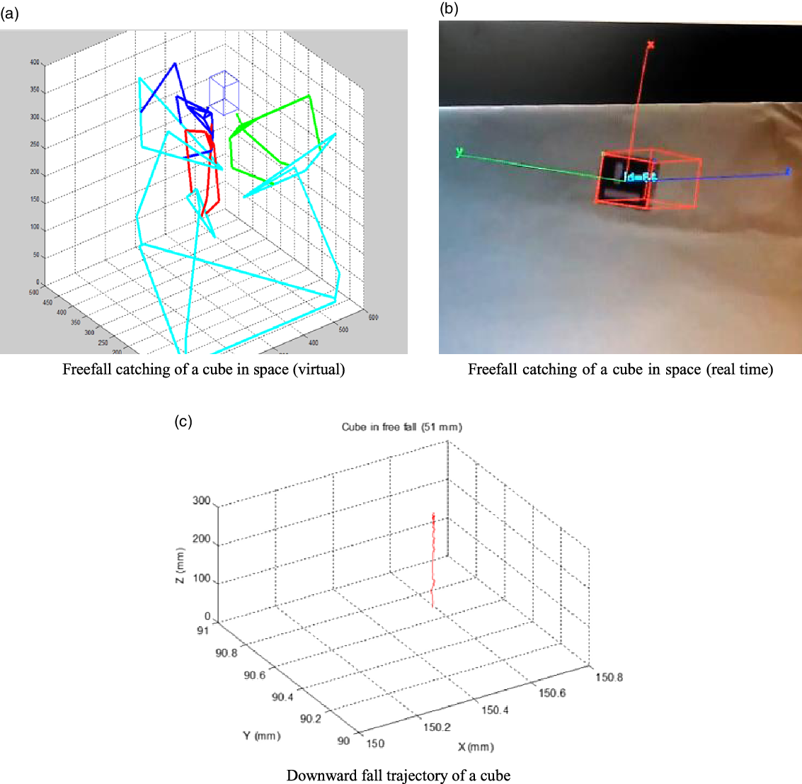
Figure 17. (a). Freefall catching of a cube in space (virtual). (b). Freefall catching of a cube in space (real time). (c). Downward fall trajectory of a cube.
The uncertainty in the camera calibration routine must be estimated to make the experimental setup robust for catching objects. The camera matrix transforms the 3D world coordinate of a point to 2D image coordinates through Eq. (1). Subsequently, differences in image coordinates between two points whose spatial relationship is known or that of the image coordinates of the same spatial point in multiple images are used to determine the object’s spatial information. Error in camera calibration occurs due to errors in creating the calibration grid and sensor chip geometry.
 \begin{equation}\lambda \textbf{p} = {\textbf{MP}}\end{equation}
where,
 \begin{align*}\textbf{p} = \left[ {\begin{array}{*{20}{c}}u\\[3pt]v\\[3pt]1\end{array}} \right]{\textbf{M}} = \left[ {\begin{array}{*{20}{c}}{{{\textrm{M}}_{11}}}\\[3pt]{{{\textrm{M}}_{21}}}\\[3pt]{{{\textrm{M}}_{31}}}\end{array}\begin{array}{*{20}{c}}{{{\textrm{M}}_{12}}}\\[3pt]{{{\textrm{M}}_{22}}}\\[3pt]{{{\textrm{M}}_{32}}}\end{array}\begin{array}{*{20}{c}}{{{\textrm{M}}_{13}}}\\[3pt]{{{\textrm{M}}_{23}}}\\[3pt]{{{\textrm{M}}_{33}}}\end{array}\begin{array}{*{20}{c}}{{{\textrm{M}}_{14}}}\\[3pt]{{{\textrm{M}}_{24}}}\\[3pt]{{{\textrm{M}}_{34}}}\end{array}} \right]\textbf{P} = \left[ {\begin{array}{*{20}{c}}{\begin{array}{*{20}{c}}X\\[3pt]Y\\[3pt]Z\end{array}}\\[3pt]1\end{array}} \right] \end{align*}
Here, u and v represent the image coordinates, and $\lambda$
is the scaling factor. P represents the world coordinates. The matrix M transforms from 3D homogeneous coordinates to 2D homogenous coordinates known as the calibration matrix. This cannot be calculated from a single point instance and is estimated using the least square method. This method estimated the 11 unknowns (M11….M33) in the M matrix using known 3D points P and measured image coordinates p. The value of M34 is 1.
$\lambda$
is the scaling factor. P represents the world coordinates. The matrix M transforms from 3D homogeneous coordinates to 2D homogenous coordinates known as the calibration matrix. This cannot be calculated from a single point instance and is estimated using the least square method. This method estimated the 11 unknowns (M11….M33) in the M matrix using known 3D points P and measured image coordinates p. The value of M34 is 1.
The average re-projected error in X-axis on re-projection is 0.105 mm, and the standard deviation is 0.115. The average re-projected error in Y-axis on re-projection is 0.115 mm, and the standard deviation is 0.071, as shown in Fig. 18.

Figure 18. Uncertainty in back-projected world coordinates.
5. Conclusion
This paper discusses the kinematic analysis of the Delta robot and its identification of the kinematic parameters using the vision sensor. In this approach, the monocular vision system has been used, which is fixed in nature, to estimate the pose of the manipulated object and perform the kinematic analysis in real time with high accuracy as the kinematic parameters of the parallel mechanism are estimated accurately to achieve the catching. The design of the controller and optimization of the parameters in real time is discussed. In various cases in real time and in the virtual environment, performing the catching of the object has been discussed. This proposed work can be applied in the automation industry to enhance the tracking and manipulating capability in a real-time environment.
Acknowledgement
We hereby acknowledge the support of Mechatronics Lab, IIT Delhi, for providing the facility and environment for carrying out the research activity.


 Open access