


1. Introduction
In the weakly turbulent, strongly stratified Arctic region, direct measurements of turbulent dissipation have been extremely scarce (e.g. Padman & Dillon Reference Padman and Dillon1987; Bourgault et al. Reference Bourgault, Hamel, Cyr, Tremblay, Galbraith, Dumont and Gratton2011; Shroyer Reference Shroyer2012; Shaw & Stanton Reference Shaw and Stanton2014), until very recently. The increasing importance of the Arctic region from the perspective of global climate and the role of the oceans in climate change processes in general has led to an increasingly sharp focus on Arctic Ocean mixing processes. This includes an increasing number of direct measurements of the viscous dissipation rate  $\varepsilon$ (see Scheifele et al. (Reference Scheifele, Waterman, Merckelbach and Carpenter2018) and Scheifele, Waterman & Carpenter (Reference Scheifele, Waterman and Carpenter2021) for example) performed in the Arctic with high-resolution conductivity–temperature–depth profilers. These new measurements are expected to significantly enhance our knowledge of vertical mixing and thereby improve the accuracy of the estimation of melt rates of Arctic sea ice.
However, in the process of inferring the operative diapycnal diffusivities from the available turbulence measurements, the historically important model of Osborn (Reference Osborn1980) has continued to be applied together with the assumption of a constant flux coefficient  $\varGamma =0.2$ for the mixing efficiency. This somewhat crude yet still fashionable methodology for the parametrization of diapycnal diffusivities may potentially lead to large systematic errors in the estimation of the diapycnal diffusivity $K_\rho$, for example, given that the canonical Osborn formula relies upon several especially questionable assumptions when it is directly applied to the Arctic Ocean environment. First, the Arctic Ocean is a strongly stratified ocean with much lower turbulence intensities compared with the low and mid-latitude oceans. Previous studies (e.g. Shih et al. Reference Shih, Koseff, Ivey and Ferziger2005) suggested that at low-turbulence intensities as usually associated with $Re_b \sim O(1)$ (where $Re_b=\varepsilon /(\nu N^2$) is the buoyancy Reynolds number, $\nu$ is the kinematic viscosity, $\varepsilon$ is the viscous dissipation rate and $N=\sqrt {-g/\rho _0 \langle {\rm d}\bar {\rho }/{\rm d} z \rangle }$ is the Brunt–Väisälä, or buoyancy, frequency, determined by gravitational acceleration g, the reference density $\rho_0$ and the vertical density gradient ${\rm d}\bar{\rho}/{\rm d}z$), the flux coefficient $\varGamma$ may reach values that are much lower than the canonical value of 0.2. Second, most of the numerical data and field measurements that support $\varGamma =0.2$ are based upon the assumption that the density is strongly determined by temperature, which is characterized by a relatively low Prandtl number ( $Pr=\nu /\kappa _\theta \sim O(1)$, where $\kappa _\theta$ is the thermal diffusivity) whereas the Arctic Ocean is a primarily salinity stratified ocean in which the Schmitt number for salinity ( $Sc=\nu /\kappa _s$, where $\kappa _s$ is the haline diffusivity) is characterized by a much higher value of approximately 700 (see Gregg et al. Reference Gregg, D'Asaro, Riley and Kunze2018). This may lead to significantly different characteristics of the diapycnal diffusivity such as that demonstrated in Rahmani, Seymour & Lawrence (Reference Rahmani, Seymour and Lawrence2016) or Bouffard & Boegman (Reference Bouffard and Boegman2013). Third, aside from the stably stratified salinity field, the main pycnocline in the Arctic also includes an unstably stratified thermocline with cold water in the surface ocean lying above the relatively warm water in the interior ocean. We will describe such circumstances as an environment in the ‘diffusive–convection regime’ in what follows, even though strictly speaking the linear ‘diffusive–convection instability’ described in the double-diffusive convection literature (see Radko Reference Radko2013) will not develop in the system as long as the density ratio $R_\rho =\beta S_z/\alpha \varTheta _z$ (sometimes referred to as inverse density ratio in the literature, where $\alpha$ is the thermal expansion coefficient and $\beta$ is the coefficient of haline contraction) is larger than $(Pr+1)/(Pr+\tau )\approx 1.08$ (evaluated based on the typical value of $Pr=13$ and diffusivity ratio $\tau =\kappa _s/\kappa _\theta =0.005$ in the Arctic Ocean, see Sharqawy, Lienhard & Zubair Reference Sharqawy, Lienhard and Zubair2010). In this circumstance it is important to take both diffusing species explicitly into account given the fact that the co-existence of the two oppositely stratified species with different diffusivities in the diffusive–convection regime is known to be able to generate fine scale structures such as those characteristic of thermohaline staircases (e.g. Timmermans et al. Reference Timmermans, Toole, Krishfield and Winsor2008) in the Arctic region. Considering the (perhaps unfounded) assumptions underlying application of the classical parametrization scheme of Osborn (Reference Osborn1980) to the Arctic environment, our major goal in the current work is to employ direct numerical simulations (DNSs) to calibrate a proper mixing parametrization scheme that is applicable to the special circumstances of the Arctic environment that might replace the Osborn methodology.
Another significant flaw in the Osborn methodology derives from its failure to differentiate between reversible turbulent stirring processes and irreversible mixing processes. In fact, Osborn's parametrization failed to recognize that only irreversible diabatic process can contribute to turbulent diapycnal diffusivity. Previous research (e.g. Winters et al. Reference Winters, Lombard, Riley and D'Asaro1995; Winters & D'Asaro Reference Winters and D'Asaro1996; Peltier & Caulfield Reference Peltier and Caulfield2003) had established that it is the evolution of the background potential energy reservoir that determines the temporal evolution of irreversible mixing. Based upon detailed energy budget analyses, Salehipour & Peltier (Reference Salehipour and Peltier2015) further proposed a formula for the irreversible diapycnal diffusivities which resembles the original Osborn formula but only takes the irreversible buoyancy flux into account. Even though the original Osborn formula correctly captures the total amount of mixing once the system enters into a stationary state, in the analysis of the instantaneous evolution of Kelvin–Helmholtz (KH) billows that will be performed in what follows, the distinction between reversible and irreversible fluxes has been shown to become very critical. It should be noticed that the distinction between reversible and irreversible processes described above had only been recognized in the study of stratified turbulence in either the single-component case or the two-component case in which both components are stably stratified scalar fields (Smyth, Nash & Moum Reference Smyth, Nash and Moum2005). The most recent work of Ma & Peltier (Reference Ma and Peltier2021) extended the analysis to include the case in which one of the scalars is unstably stratified. This was first applied to the case of salt-fingering double-diffusive turbulence, which develops under conditions in which warm salty water lies above relatively colder and fresher water. As we will demonstrate in what follows, the theoretical framework established in Ma & Peltier (Reference Ma and Peltier2021) that is based on sorting both individual fields separately can be carried over almost without modification to the diffusive–convection system with only the roles played by temperature and salinity in the energy budget switched. In what follows, the formulae for the irreversible diapycnal diffusivities for both heat and salt will be derived that provide the basis for the new mixing analysis to be discussed herein. It will be important to recognize that an alternative definition of background potential energy for double diffusion is provided in the recent work of Middleton & Taylor (Reference Middleton and Taylor2020). In this work, only the density field is sorted and the separate definitions of irreversible heat fluxes and irreversible salt fluxes, which are important in our analyses to follow, cannot be defined. For this reason, we will employ the method discussed in Ma & Peltier (Reference Ma and Peltier2021) as the basis for our turbulent analyses.
In what follows this analysis will be based on a series of DNS analyses that simulate mixing induced by the development and the breakdown into turbulence of a primary KH instability in the diffusive–convection environment. KH instability has always been considered to be the dominant mechanism responsible for mixing the ocean pycnocline (Gregg et al. Reference Gregg, D'Asaro, Riley and Kunze2018). It has been well studied by water tank experiments (e.g. Thorpe Reference Thorpe1973; Patterson et al. Reference Patterson, Caulfield, McElwaine and Dalziel2006) and an extensive amount of theoretical analysis and DNS-based numerical simulations as a basis for understanding the nature of the lifecycle in single-component fluids (see the recent review of Caulfield Reference Caulfield2021). Through a combination of secondary instability analyses and DNSs in the past fifty years (e.g. Corcos & Sherman Reference Corcos and Sherman1976; Davis & Peltier Reference Davis and Peltier1976; Klaassen & Peltier Reference Klaassen and Peltier1985; Palmer et al. Reference Palmer, Fritts, Andreassen and Lie1994; Staquet Reference Staquet1995; Caulfield & Peltier Reference Caulfield and Peltier2000; Staquet Reference Staquet2000; Mashayek & Peltier Reference Mashayek and Peltier2012a,Reference Mashayek and Peltierb; Salehipour, Peltier & Mashayek Reference Salehipour, Peltier and Mashayek2015), the ‘zoo’ of secondary instabilities that drive the primary KH billow to turbulence has been well understood and which secondary instabilities from the ‘zoo’ dominate the turbulent transition is largely determined by the Reynolds number of the flow (Mashayek & Peltier Reference Mashayek and Peltier2012a,Reference Mashayek and Peltierb). Furthermore, mixing efficiencies and diapycnal diffusivities for density have been shown to vary significantly as different secondary instabilities are involved in driving the system into a fully turbulent state (Mashayek & Peltier Reference Mashayek and Peltier2013). It has also been demonstrated that mixing efficiencies are also strongly dependent on the background stratification and the Prandtl number (see Caulfield & Peltier Reference Caulfield and Peltier2000; Salehipour et al. Reference Salehipour, Peltier and Mashayek2015; Rahmani et al. Reference Rahmani, Seymour and Lawrence2016) being employed.
Although the evolution of the classical KH billows and their influence on mixing have been well studied in the literature, they have never been studied in the diffusive–convection environment which has to be considered in the context of understanding Arctic stratification and mixing. In fact, the coexistence of temperature and salinity fields in the development of KH billows has been studied in the system in which both temperature and salinity fields were set to be stably stratified (Smyth et al. Reference Smyth, Nash and Moum2005) as well as in the system that favours the salt-fingering stratification (Kimura, Smyth & Kunze Reference Kimura, Smyth and Kunze2011; Smyth & Kimura Reference Smyth and Kimura2011). It has been found in Smyth et al. (Reference Smyth, Nash and Moum2005) that the differential diffusion (the differences in the diapycnal diffusivities between temperature and salinity) only becomes significant when  $Re_b$ is smaller than 100. In the work to be discussed in the current paper, we will perform DNSs of KH billow engendered turbulence that develops in the diffusive–convection environment to discuss its mixing properties and compare them with the existing literature on single-component systems and the doubly stable systems of Smyth et al. (Reference Smyth, Nash and Moum2005). By performing these analyses, we will demonstrate that the diapycnal diffusivities for heat and salt operate independently of one another being coupled only through the buoyancy Reynolds number $Re_b$. It is worth remarking that this conclusion actually provides critical support for an assumption underlying our recent paper (Ma & Peltier Reference Ma and Peltier2022) in which we have described a new mechanism for the formation of thermohaline staircases in the diffusive–convection environment of the Arctic Ocean. The basic assumption of Ma & Peltier (Reference Ma and Peltier2022) is that the diapycnal diffusivities for heat and salt are only a function of $Re_b$. That this assumption in that paper is verified by the DNS-based turbulence analyses to be presented in what follows will be one of the major conclusions of the current paper.
The remainder of the present paper is organized as follows. In § 2 we will discuss the governing formulae for mixing in the diffusive–convection environment by performing a detailed energy budget analysis that differentiates the irreversible and reversible processes. We will then discuss the numerical settings for our DNSs on KH instability and subsequent turbulent mixing in § 3. The time evolution of KH lifecycles in these simulations will be discussed and compared for simulations with different non-dimensional parameters in § 4. In the ensuing § 5 we will specifically discuss the functional dependence of the diapycnal diffusivities for heat and salt in order to compare them with the existing data-based parametrization of Bouffard & Boegman (Reference Bouffard and Boegman2013). Based on these discussions, a new algorithm is provided at the end of § 5 for future implementation to improve the understanding of Arctic Ocean turbulence measurements. Finally, we will offer a summary and conclusions of the results obtained in this paper in § 6.
2. Scalar diffusivities in a diffusive–convection system
The Osborn (Reference Osborn1980) formula continues to be widely employed to estimate the diapycnal diffusivity for density  $K_\rho$ based on the measured viscous dissipation rate in the field of physical oceanography. His formulation of the mixing problem for a single-component fluid has recently been tested by Salehipour & Peltier (Reference Salehipour and Peltier2015) in order to produce results for turbulent diffusivity that involve only irreversible mixing processes. In the formulation of the mixing problem in this section we will properly extend the results of Salehipour & Peltier (Reference Salehipour and Peltier2015) to apply to the diffusive–convection circumstance in which the stratification is determined simultaneously by a stably stratified salinity field and an unstably stratified temperature field, as is characteristic of the Arctic Ocean environment. Therefore, we will first review both the canonical models of Osborn (Reference Osborn1980) as well as the modified form of Osborn's formulation described by Salehipour & Peltier (Reference Salehipour and Peltier2015). This will be followed by presentation of a careful energy budget analysis and the new formulae that apply to the case of Arctic Ocean turbulence that is of interest to us here.
2.1. Previous representation of scalar diffusivity in the single-component fluid
The Osborn (Reference Osborn1980) formulation of the mixing-efficiency problem was derived on the basis of the following simplified equation for the conservation of turbulent kinetic energy:
 \begin{equation} \mathcal{P}=\mathcal{H}+\varepsilon, \end{equation}
in which the shear production of the background flow is  $\mathcal {P}$, the turbulent buoyancy flux is $\mathcal {H}$ and the viscous dissipation is $\varepsilon$, all of which are defined as follows:
 $$\begin{gather} \mathcal{P}={-\left\langle \overline{u'w'} \frac{{\rm d}\bar{u}}{{\rm d} z} \right\rangle}, \end{gather}$$
 $$\begin{gather}\mathcal {H}=\frac{g}{\rho_0} \langle \overline{\rho'w'}\rangle, \end{gather}$$
 $$\begin{gather}\varepsilon=2\nu \overline{\langle s_{ij}s_{ij} \rangle}. \end{gather}$$
In above equations, the overbar on a variable  $\bar {f}$ represents the horizontal average of the field $f$, the bracket $\langle\, \cdot\, \rangle$ represents the vertical average, $\boldsymbol {u}=(u,v,w)$ is the velocity field that is further separated into the horizontally averaged fields $\bar {\boldsymbol {u}}$ and the perturbated field $\boldsymbol {u}'$ to it; $\rho _0$ is the reference density and $\rho '=\rho -\rho _0$ is the density perturbation; $s_{ij}=(\partial u_i/\partial x_j+\partial u_j/\partial x_i)/2$ is the strain rate tensor.
By employing the definition of the flux Richardson number  $R_f=\mathcal {H}/\mathcal {P}$, Osborn (Reference Osborn1980) wrote the diapycnal diffusivity $K^{Osb}_\rho$ in the form of
 $$\begin{gather} K^{Osb}_\rho=\frac{\mathcal{H}}{N^2}=\nu \frac{\mathcal{H}}{\varepsilon} \frac{\varepsilon}{\nu N^2}=\nu \varGamma^{Osb} Re_b, \end{gather}$$
 $$\begin{gather}\varGamma^{Osb}=\frac{\mathcal{H}}{\varepsilon}=\frac{R_f}{1-R_f}, \end{gather}$$
in which  $\varGamma ^{Osb}$ is usually referred to as the flux coefficient and the value 0.2 was estimated to be the upper bound for $\varGamma ^{Osb}$ in the original work of Osborn (Reference Osborn1980). In the subsequent practical application of this formulation of the mixing problem, $\varGamma ^{Osb}$ has always been assumed to be equal to the constant value 0.2 when applied to the understanding of oceanographic measurements. This is in spite of the fact that there exists significant evidence from simulations demonstrating that the value of $\varGamma =0.2$ may not be accurate (see the recent review of Gregg et al. (Reference Gregg, D'Asaro, Riley and Kunze2018) concerning its application in the field of oceanography).
However, as pointed out by Winters et al. (Reference Winters, Lombard, Riley and D'Asaro1995) and Peltier & Caulfield (Reference Peltier and Caulfield2003), the buoyancy flux defined in (2.1) contains the influence of both irreversible and reversible mixing processes whereas only the irreversible component should contribute to mixing when this is represented by a diapycnal diffusivity. In order to differentiate true irreversible mixing from adiabatic stirring, a background potential energy  $BPE$ is defined by ‘sorting’ the three-dimensional density field into a vertical profile $\rho _\ast (z,t)$ with a decreasing upwards density $BPE=g/\rho _0 \overline {\langle \rho _*(z,t) z \rangle }$. The energy stored in this background potential energy reservoir is the minimum potential energy which cannot be transformed into kinetic energy. On the other hand, the differences between this $BPE$ and the total potential energy $PE=g/\rho _0 \overline {\langle \rho z \rangle }$ is defined as the available potential energy ( $APE$), as this part of the potential energy is ‘available’ to be transferred back to macroscopic motion. In a closed domain (no body force, no boundary flux), the time derivative of the $BPE$ can be shown (Winters & D'Asaro Reference Winters and D'Asaro1996) to be
 $$\begin{gather} \frac{{\rm d}}{{\rm d} t}BPE=\mathcal{M}+\mathcal{D}_p, \end{gather}$$
 $$\begin{gather}\mathcal{M}+\mathcal{D}_p= \frac{\kappa g}{\rho_0 V}\int_V -\frac{{\rm d} z}{{\rm d} \rho_*} |\boldsymbol{\nabla} \rho|^2 \,{\rm d} V. \end{gather}$$
In above equations,  $\kappa$ is the density diffusivity in the single-component system. Since ${\rm d} BPE/{\rm d} t$ is always positive, $BPE$ is a monotonically increasing function in time. Here, $\mathcal {M}$ is the irreversible buoyancy flux that characterizes the instantaneous mixing strength across the pycnocline that is generated due to the macroscopic fluid motion and $\mathcal{D}_p$ characterizes the part of mixing that would occur even in a completely motionless flow. In fact, $\mathcal{D}_p$ is always negligible if any form of turbulence is developed in a system that is not incredibly small so that the second equation in (2.4) can also be treated as the definition for $\mathcal {M}$.
Based on these definitions, Salehipour & Peltier (Reference Salehipour and Peltier2015) derived a modified expression for the diapycnal diffusivities in which the flux Richardson number  $R_f$ in (2.3) is replaced by the irreversible mixing efficiency $\mathcal {E}$ as
 $$\begin{gather} K^{irr}_\rho=\nu \frac{\mathcal{M}}{\varepsilon}\frac{\varepsilon}{\nu N_*^2} =\nu \varGamma^{irr} Re_{b*}, \end{gather}$$
 $$\begin{gather}\varGamma^{irr}= \frac{\mathcal{M}}{\varepsilon} =\frac{\mathcal{E}}{1-\mathcal{E}}, \end{gather}$$
in which  $N_*^2$ is the squared buoyancy frequency in the sorted profile but is always identical to the traditional definition of $N^2$ (see Salehipour & Peltier (Reference Salehipour and Peltier2015), so that $Re_{b*}=Re_b$). Equations (2.5) have the same form as (2.3), except that the irreversible versions of physical quantities in (2.5) are employed in place of Osborn's original expressions. Through these modifications, the formulae now correctly define the diapycnal diffusivities in terms of quantities involving irreversible mixing processes.
2.2. Scalar diffusivities in the presence of two diffusing species
We will here proceed to extend (2.5) to a diffusive–convection system, following similar approaches that were applied in Ma & Peltier (Reference Ma and Peltier2021) to the understanding of diapycnal diffusivities in salt-fingering turbulence. The existence of the unstably stratified scalar field of temperature in the Arctic Ocean region allows potential energy to kinetic energy conversion and thereby the creation of macroscopic motion, which was unavailable in the single-component case in which the background stratification of density was stably stratified. Thus, an energy budget analysis will be needed in order for a correct characterization of the diapycnal diffusivities for both scalars to be defined.
The total kinetic energy per unit mass may be represented as  $\mathcal {K}=\overline {|\boldsymbol {u}^2|}/2$. Based on the assumption of the linear equation of state $\rho = \rho _0(1 -\alpha (\varTheta -\varTheta _0) + \beta (S-S_0))$ (thermal expansion rate $\alpha$ and haline contraction rate $\beta$ are both assumed to be constant), we define the averaged potential energy per unit mass and decompose it into a temperature reservoir $PE_\varTheta$ and a salinity reservoir $PE_S$ as follows:
 \begin{align} PE &= \frac{g}{\rho_0}\overline{ \langle \rho z\rangle} , \nonumber\\ &={-}g\alpha \overline{\langle \varTheta z\rangle}+g\beta \overline{\langle S z\rangle} + { g\overline{\langle z\rangle}}, \nonumber\\ &= PE_\varTheta+PE_S+ PE_0. \end{align}
Here,  $PE_0$ is a constant term that will be ignored in what follows.
The time derivatives of  $\mathcal {K}$, $PE$,
$PE$,  $PE_\varTheta$, $PE_S$ can be derived straightforwardly by assuming that the two fluid components obey the Boussinesq governing equations which leads to the system
 \begin{align} \frac{{\rm d} \mathcal{K}}{{\rm d} t} &={-}\mathcal{H}_\varTheta-\mathcal{H}_S-\varepsilon, \end{align}
 \begin{align} \frac{{\rm d} PE_\varTheta}{{\rm d} t} &= \mathcal{H}_\varTheta+\mathcal{D}_{p\varTheta}, \end{align}
 \begin{align} \frac{{\rm d} PE_S}{{\rm d} t} &= \mathcal{H}_S+\mathcal{D}_{pS}, \end{align}
 \begin{align} \frac{{\rm d} PE}{{\rm d} t} &= \frac{{\rm d} PE_\varTheta}{{\rm d} t}+\frac{{\rm d} PE_S}{{\rm d} t} ,\nonumber\\ &= \mathcal{H}_\varTheta+\mathcal{H}_S+\mathcal{D}_{p\varTheta}+\mathcal{D}_{pS}, \nonumber\\&=\mathcal{H}+\mathcal{D}_{p}, \end{align}
where
 $$\begin{gather} \mathcal{H}_\varTheta ={-}g\alpha \overline{\langle \varTheta' w' \rangle}, \end{gather}$$
 $$\begin{gather}\mathcal{H}_S = g\beta \overline{\langle S'w' \rangle}, \end{gather}$$
 $$\begin{gather}\mathcal{D}_{p\varTheta} = g\alpha \kappa_\theta \overline{\left\langle \frac{\partial \varTheta}{\partial z} \right\rangle}, \end{gather}$$
 $$\begin{gather}\mathcal{D}_{pS} ={-} g\beta \kappa_s \overline{ \left\langle \frac{\partial S}{\partial z} \right\rangle}. \end{gather}$$
Just as in the single-component case, the buoyancy fluxes  $\mathcal {H}_S$ and $\mathcal {H}_\varTheta$ contain the contributions from both reversible processes and irreversible processes. The reversible fluxes capture the energy transfer between the kinetic energy reservoir and the available potential energy reservoirs $APE_S$ and $APE_\varTheta$, while the irreversible fluxes transfer energy between $APE_S$ and $APE_\varTheta$ and the background potential energies $BPE_S$ and $BPE_\varTheta$. Specifically, the background potential energies $BPE_\varTheta$ and $BPE_S$ are defined as the part of the potential energy that is associated with adiabatic re-arrangements of the temperature and salinity profiles to monotonically decreasing profiles $\varTheta (z_{\theta \ast })$ and $S(z_{s\ast })$ and $APE_\varTheta$ and $APE_S$ describes the differences between total energies and background potential energies, namely
 $$\begin{gather} BPE_\varTheta={-}g\alpha \overline{\langle \varTheta(z_{\theta\ast},t) z_{\theta\ast} \rangle}, \end{gather}$$
 $$\begin{gather}BPE_S=g \beta \overline{\langle S(z_{s\ast},t) z_{s\ast} \rangle}, \end{gather}$$
 $$\begin{gather}APE_\varTheta=PE_\varTheta-BPE_\varTheta, \end{gather}$$
 $$\begin{gather}APE_S=PE_S-BPE_S. \end{gather}$$
 The irreversible buoyancy fluxes for heat ( $\mathcal {M}_\varTheta$) and salt ( $\mathcal {M}_S$) again characterize the time derivative of $BPE_\varTheta$ and $BPE_S$ in a closed system as
 \begin{align} \frac{{\rm d}}{{\rm d}
t}BPE_\varTheta &= g\alpha \kappa_\theta
\left\langle\frac{{\rm d} z_{\theta\ast}}{{\rm
d}\varTheta}|\boldsymbol{\nabla} \varTheta|^2\right\rangle,
\nonumber\\ &= \mathcal{M}_{\varTheta}+D_{p
\varTheta},\end{align}
\begin{align} \frac{{\rm d}}{{\rm d}
t}BPE_\varTheta &= g\alpha \kappa_\theta
\left\langle\frac{{\rm d} z_{\theta\ast}}{{\rm
d}\varTheta}|\boldsymbol{\nabla} \varTheta|^2\right\rangle,
\nonumber\\ &= \mathcal{M}_{\varTheta}+D_{p
\varTheta},\end{align}
 \begin{align} \frac{{\rm d}}{{\rm d} t}BPE_S &={-}g\beta \kappa_s \left\langle \frac{{\rm d} z_{s\ast}}{{\rm d} S}|\boldsymbol{\nabla} S|^2\right\rangle, \nonumber\\ &= \mathcal{M}_{S}+D_{pS}, \end{align}
 \begin{align} \frac{{\rm d}}{{\rm d} t}BPE &= \frac{{\rm d}}{{\rm d} t}BPE_\varTheta+\frac{{\rm d}}{{\rm d} t}BPE_S, \nonumber\\ &= \mathcal{M}_{\varTheta}+\mathcal{M}_{S}+D_{p \varTheta}+D_{p S}, \nonumber\\ &\equiv \mathcal{M}+D_{p}. \end{align}
The above sets of equations imply simply that, while  $BPE_S$ is a monotonical increasing function with time as in the traditional definition of background potential energy for a single-component fluid, $BPE_\varTheta$ is a monotonically decreasing function which irreversibly releases energy to $APE_\varTheta$ which can then be transported to the kinetic energy reservoir. The total background potential energy $BPE$, however, can either increase or decrease with time, depending upon the relative strengths of the negative $\mathcal {M}_{\varTheta }$ and positive
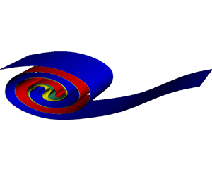
  $\mathcal {M}_{S}$ in the system. The energy exchanges described above can also be visualized in the simplified diagram shown in figure 1. It should be noticed that the $APE_\varTheta$ has a slightly different meaning from the traditional implication of available potential energy; while available potential energy usually refers to the amount of potential energy stored by the reversible process that is available to be released to the kinetic energy reservoir in the single-component case (also applies for $APE_S$), here, $APE_\varTheta$ (having a negative value through its definition) represents the amount of energy that has already been transported into the kinetic energy reservoir. However, this part of energy is lost through a reversible process so that it could possibly be transported back through convection in the future evolution of the flow field. Combining $APE_\varTheta$ and $APE_S$, the $APE$ reservoir represents the part of the potential energy that can be exchanged with the kinetic energy reservoir through reversible processes.

Figure 1. Graphical demonstration of energy budgets in the diffusive–convection environment. The direction of the energy flow of the positive/negative transportation is clarified using arrows.
Given the definition of the irreversible buoyancy fluxes  $\mathcal{M}_\varTheta$ and $\mathcal{M}_S$ above, we can derive the irreversible diapycnal diffusivities for heat and salt as follows:
 \begin{align} K^{irr}_\varTheta &= \frac{\mathcal{M}_\varTheta}{ g \alpha \left\langle \dfrac{{\rm d} \varTheta}{{\rm d} z_{\theta \ast}} \right\rangle }, \end{align}
 \begin{align} &= \nu \frac{\mathcal{M}_\varTheta}{\varepsilon} \frac{ N^2 }{ g \alpha \left\langle \dfrac{{\rm d} \varTheta}{{\rm d} z_{\theta \ast}} \right\rangle} \frac{\varepsilon}{\nu N^2 }, \end{align}
 \begin{align} &= \nu \frac{\mathcal{M}_\varTheta}{\varepsilon} \frac{ R_{\rho \ast}-1 }{-1} \frac{\varepsilon}{\nu N^2 }, \end{align}
 \begin{align} &= \nu \varGamma^{irr}_{\varTheta} Re_b, \end{align}
 \begin{align} K^{irr}_S &={-}\frac{\mathcal{M}_S}{ g \beta \left\langle \dfrac{{\rm d} S}{{\rm d} z_{s \ast}} \right\rangle }, \end{align}
 \begin{align} &={-}\nu \frac{\mathcal{M}_S}{\varepsilon} \frac{ N^2 }{ g \beta \left\langle \dfrac{{\rm d} S}{{\rm d} z_{s \ast}}\right\rangle} \frac{\varepsilon}{\nu N^2 }, \end{align}
 \begin{align} &= \nu \frac{\mathcal{M}_S}{\varepsilon} \frac{ R_{\rho \ast}-1 }{R_{\rho \ast}} \frac{\varepsilon}{\nu N^2 }, \end{align}
 \begin{align} &= \nu \varGamma^{irr}_{S} Re_b, \end{align}
where
 $$\begin{gather} R_{\rho \ast}\equiv\frac{\beta \left\langle \dfrac{{\rm d} S}{{\rm d} z_{s \ast}} \right\rangle}{ \alpha \left\langle \dfrac{{\rm d} \varTheta}{{\rm d} z_{\theta \ast}} \right\rangle}, \end{gather}$$
 $$\begin{gather}\varGamma^{irr}_\varTheta \equiv \frac{- (R_{\rho \ast}-1) \mathcal{M}_\varTheta} {\varepsilon}, \end{gather}$$
 $$\begin{gather}\varGamma^{irr}_{S} \equiv \frac{(R_{\rho \ast}-1)\mathcal{M}_S }{\varepsilon R_{\rho \ast}}. \end{gather}$$
In above equations,  $R_{\rho \ast }$ is always identical to the traditional $R_\rho$ (due to the same reason that $N_\ast ^2$ is identical to $N^2$, which we have mentioned above) so that we will not differentiate them in what follows. Also, $\varGamma ^{irr}_{\varTheta }$ and $\varGamma ^{irr}_S$ are defined as the flux coefficients for temperature and salinity separately ( $\varGamma ^{irr}_{\varTheta }$ has also been previously introduced as ‘the dissipation ratio’ in the literature e.g. Laurent & Schmitt Reference St. Laurent and Schmitt1999). Since the overall stratification is stable we have $R_\rho >1$, this leads to the fact that both $\varGamma ^{irr}_{\varTheta }$ and $\varGamma ^{irr}_S$ are positive, guaranteeing that the diapycnal diffusivities for both scalars $K^{irr}_\varTheta$, $K^{irr}_S$ are positive.
Meanwhile, the diapycnal diffusivity for density can be derived in the form of the density flux coefficient as
 \begin{align} K^{irr}_\rho&=\frac{\mathcal{M}}{ N^2 }, \end{align}
 \begin{align} &=\nu \frac{\mathcal{M}}{\varepsilon} \frac{\varepsilon}{\nu N^2 }, \end{align}
 \begin{align} &=\nu \varGamma^{irr}_\rho Re_b. \end{align}
By employing the buoyancy flux  $\mathcal {M}$ as a summation of $\mathcal {M}_\theta$ and $\mathcal {M}_s$, it is straightforward to show that $\varGamma ^{irr}_{\rho }$ (or $K^{irr}_\rho$) can be determined by $\varGamma ^{irr}_{\varTheta }$ (or $K^{irr}_\varTheta$) and $\varGamma ^{irr}_{S}$ (or $K^{irr}_S$) from
 $$\begin{gather} \varGamma^{irr}_\rho=\frac{R_\rho}{R_\rho-1} \varGamma^{irr}_S -\frac{1}{R_\rho-1} \varGamma^{irr}_\varTheta, \end{gather}$$
 $$\begin{gather}K^{irr}_\rho=\frac{R_\rho}{R_\rho-1} K^{irr}_S -\frac{1}{R_\rho-1} K^{irr}_\varTheta. \end{gather}$$
Although  $K^{irr}_\varTheta$ and $K^{irr}_S$ are both positive, as has been demonstrated above, (2.14) shows that $K^{irr}_\rho$ can be negative if the temperature term dominates. As we will see below, this situation might occur in the early and late evolution stage of KH instability growth in the strongly stratified case, in which situation the strength of the turbulence is weak enough and the temperature mixes more efficiently than salinity.
As in the single-component case, the irreversible flux coefficient  $\varGamma ^{irr}_\rho$ can be written in the form of instantaneous mixing efficiency as
 $$\begin{gather} \varGamma^{irr}_\rho=\frac{\mathcal{E}}{1-\mathcal{E}}, \end{gather}$$
 $$\begin{gather}\mathcal{E}=\frac{\mathcal{M}}{\mathcal{M}+\varepsilon}= \frac{\mathcal{M}_\varTheta+\mathcal{M}_S}{\mathcal{M}_\varTheta+\mathcal{M}_S+\varepsilon}. \end{gather}$$
In the single-component case  $\mathcal {E}$ always remains in the range $0<\mathcal {E}<1$ and clearly represents the amount of irreversible mixing relative to the viscous dissipation. However, in the diffusive–convection environment $\mathcal {E}$ can take both negative values and values that are much larger than 1, in the cases of $\mathcal {M}<0$ following its definition in (2.15). Therefore, $\mathcal {E}$ no longer carries the meaning of ‘efficiency’ in the doubly diffusive system and we will employ the flux-coefficient form of the diffusivities in (2.11) rather than the mixing-efficiency form in our analyses in what follows.
Another important physical quantity is the ratio of (irreversible) diapycnal diffusivity for salinity to that for temperature, namely
 \begin{equation} d=\frac{K^{irr}_S}{K^{irr}_\varTheta}. \end{equation}
The ratio of diapycnal diffusivities  $d$ has been widely used in the literature (e.g. Gargett, Merryfield & Holloway Reference Gargett, Merryfield and Holloway2003; Merryfield Reference Merryfield2005; Smyth et al. Reference Smyth, Nash and Moum2005; Jackson & Rehmann Reference Jackson and Rehmann2009) to characterize the degree of differential diffusivity in the system where both temperature and salinity fields are stably stratified. These analyses demonstrate that $d$ is close to unity in the strong turbulence limit, but decreases rapidly as turbulence intensity decreases or stratification strengthens, see Gregg et al. (Reference Gregg, D'Asaro, Riley and Kunze2018) for further discussion.
The above formulae provide us with the theoretical basis required for calibration of the irreversible components of diapycnal diffusivities in studies of doubly diffusive turbulence. Using DNSs that we will introduce in the next section, we will investigate quantitively how energy is transferred between the different energy reservoirs and how the irreversible diapycnal diffusivities evolve in a typical KH life cycle.
3. Parameter choices for DNSs of KH instability with two oppositely diffusing species
In this section we will discuss the design of the DNSs to be employed to study the evolution of the KH billow and the turbulence to which this evolution gives rise. We will first discuss how the KH system is formulated in § 3.1, which will be followed by a discussion of the detailed numerical methodology to be employed in § 3.2.
3.1. Theoretical preliminaries
In order to study the mixing induced by vertical shear in a system stratified in both temperature and salinity, we apply the idealized initial vertical profiles for horizontal velocity, temperature and salinity as follows:
 $$\begin{gather} u(x,y,z,t=0)=U_0 \tanh \left(\frac{z}{h} \right), \end{gather}$$
 $$\begin{gather}\varTheta(x,y,z,t=0)={-}\Delta \varTheta \tanh \left(\frac{z}{h} \right), \end{gather}$$
 $$\begin{gather}S(x,y,z,t=0)={-}\Delta S \tanh \left(\frac{z}{h} \right), \end{gather}$$
where ( $x,y,z$) are the streamwise, spanwise and vertical directions (positive $z$ direction is set to be antiparallel with gravity), respectively, and ( $u,v,w$) represents the velocity component in each of these directions; $h$ is half the thickness for the shear layer (which is also half the thickness of the salinity and temperature interfaces in the model system to be employed), $\Delta \varTheta$, $\Delta S$ and $U_0$ are half the variations of initial temperature, salinity and horizontal velocity profiles across the interface, as shown in the sketch of these initial profiles in figure 2. Both $\varTheta (z)$ and $S(z)$ will contribute to the density through an idealized linear equation of state $\rho = \rho _0(1 -\alpha \varTheta + \beta S)$. To mimic the stratification in the Arctic region, we have relatively colder and fresher water above warmer and saltier water while keeping the density profile gravitationally stable. This requires that the stably stratified salinity contributes more to density than the unstably stratified temperature profile, namely $\Delta \rho =\beta \Delta S-\alpha \Delta \varTheta >0$, as illustrated in figure 2.

Figure 2. Sketch of initial condition for the scalar fields (a) and streamwise velocity field (b) in our KH simulation. In (a) the dashed, dotted and sold lines represent  $S(z)$, $\varTheta (z)$ and $\rho (z)$, respectively.
The flows of interest to us will be described by the (non-dimensional) Boussinesq approximation with the system
 $$\begin{gather} \frac{\partial \boldsymbol{u}}{\partial t}+\boldsymbol{u}\boldsymbol{\cdot}\boldsymbol{\nabla} \boldsymbol{u}={-}\boldsymbol\nabla p -J \left(\frac{R_\rho}{R_\rho-1}S -\frac{1}{R_\rho-1} \varTheta\right) \boldsymbol{e_z}+\frac{1}{Re}\nabla^2\boldsymbol{u}, \end{gather}$$
 $$\begin{gather}\boldsymbol{\nabla}\boldsymbol{\cdot} \boldsymbol{u} = 0, \end{gather}$$
 $$\begin{gather}\frac{\partial \varTheta}{\partial t}+\boldsymbol{u}\boldsymbol{\cdot}\boldsymbol{\nabla} \varTheta =\frac{1}{Re\,Pr}\nabla^2\varTheta, \end{gather}$$
 $$\begin{gather}\frac{\partial S}{\partial t}+ \boldsymbol{u}\boldsymbol{\cdot}\boldsymbol{\nabla} S= \frac{1}{Re\,Sc} \nabla^2S, \end{gather}$$
in which the non-dimensionalization has employed  $h$ as the length scale and $\Delta \varTheta$, $\Delta S$ and $U_0$ as the temperature, salinity and velocity scales, respectively. The five non-dimensional control parameters in this set of field equations are the Reynolds number $Re$, the bulk Richardson number $J$, the density ratio $R_\rho$, the Prandtl number $Pr$ as well as the Schmidt number $Sc$, which are defined as follows:
 $$\begin{gather} Re=\frac{U_0 h}{\nu}, \end{gather}$$
 $$\begin{gather}J=\frac{g\Delta \rho h}{\rho_0 U_0^2}=\frac{g(\beta \Delta S-\alpha \Delta \varTheta) h}{\rho_0U_0^2}, \end{gather}$$
 $$\begin{gather}R_\rho=\frac{\beta \Delta S}{\alpha \Delta \varTheta}, \end{gather}$$
 $$\begin{gather}Pr=\frac{\nu}{\kappa_\theta}, \end{gather}$$
 $$\begin{gather}Sc=\frac{\nu}{\kappa_s}. \end{gather}$$
Compared with the single-component fluid upon which most studies of KH instability to date have focused, we have introduced the Schmitt number  $Sc$ and the density ratio $R_\rho$ into the parameter space; $Sc$ represents the ratio of momentum diffusivity to the salinity diffusivity in the ocean. It is usually much higher than $Pr$ due to much lower diffusivity of salinity compared with that of heat. The density ratio $R_\rho$ characterizes the relative importance of salinity and temperature to the stratification of density, a parameter which lies in the range of $1< R_\rho <\infty$ in the system which is our intention to study. In the limit of $R_\rho \to \infty$, the unstably stratified temperature field $\varTheta (x,y,z,t)$ is decoupled from the momentum equation in (3.2a), so that the system described by (3.1) and (3.2) essentially returns to that for a single-component fluid whose stratification is entirely determined by salinity. On the other hand, if $R_\rho$ is close to 1, the unstably stratified component in the system becomes so strong that the system will also be susceptible to the buoyancy induced oscillatory diffusive–convection instability. In this scenario, the system is difficult to investigate numerically since both shear-driven instability and buoyancy-driven instability are involved and the widely separated length scales are activated simultaneously. More importantly, this small density ratio region of parameter space has seldom been observed in the Arctic ocean (Shibley et al. Reference Shibley, Timmermans, Carpenter and Toole2017). For this reason we will open our discussion in this paper to a much wider range of density ratio $R_\rho \ge 2$ that is more representative of observed conditions in the Arctic Ocean.
3.2. Detailed design characteristics of the ensemble of DNSs
Governing equations (3.2) are integrated in a hexahedron of size  $(L_x,L_y,L_z)$ using the open-source computational fluid dynamics solver Nek5000 (Paul, James & Kerkemeier Reference Paul, James and Kerkemeier2008). Nek5000 was originally developed at Argonne National Laboratory based on the spectral element method in such a way as to support a user-defined complex geometry (see Fischer (Reference Fischer1997) and Fischer, Kruse & Loth (Reference Fischer, Kruse and Loth2002) for example). It is well suited to simulating highly turbulent flows (see Salehipour et al. (Reference Salehipour, Peltier and Mashayek2015) and Ma & Peltier (Reference Ma and Peltier2021) for example) since it allows users to economically design the computational mesh in such a way as to contain higher resolution in more strongly turbulent regions and lower resolution elsewhere.
The detailed information for each of our numerical simulations that are to be discussed in this paper is summarized in table 1. We integrate the doubly diffusive systems with different initial bulk Richardson numbers  $J$ and different density ratios $R_\rho$ to investigate their influences on the evolution of the KH lifecycle. We furthermore perform control simulations of the single-component KH billow (simulation numbers 4 and 7) to illustrate in detail how the introduction of another diffusing species will influence the evolution of KH billows. For most of the simulations performed in this paper, we set the streamwise extent of our domain $L_x$ to contain one wavelength of the fastest growing mode of linear instability, except in simulation number 5, in which we select the domain length to contain twice the fastest growing wavelength in order to investigate the secondary pairing instability that we will describe in the next section. The spanwise extent of the domain $L_y$ is set to be 5 $h$ and a slightly smaller domain of 3 $h$ has been selected for the high-resolution simulation numbers 5 and 6, both of which have been shown to be large enough to ensure that the fastest growing modes of secondary cross-stream instabilities are adequately resolved (Mashayek & Peltier Reference Mashayek and Peltier2011). The value of $L_z$ is set to 20 $h$ in all these simulations.
Table 1. Governing parameters for the DNSs discussed in this paper.

It is notoriously difficult to perform DNSs that involve the evolution of the salinity field: the low haline diffusivity requires an extremely high resolution so that the Batchelor scale for salinity  $L_B=(\nu \kappa ^2_s/ \varepsilon )^{1/4}$ can be resolved in our DNS grids. To this end we employ compromise values of $Sc=70$ and $Pr=7$, a condition which has relatively mild mesh requirements while keeping an order of magnitude difference between the salinity and temperature diffusivities. Meanwhile, the small Batchelor scale that needs to be resolved in DNS also exerts a constraint on the Reynolds number: a value of $Re=600$ provides the $L_B$ value that is required for our current simulations. As will be demonstrated in what follows, this intermediate value of the Reynolds number will lead to values of the buoyancy Reynolds number in the turbulent phase of billow evolution of $O(10)$, which is in the range of moderate turbulent intensity observed to characterize Arctic Ocean turbulence, as discussed in Dosser et al. (Reference Dosser, Chanona, Waterman, Shibley and Timmermans2021). To design the most efficient mesh for each of these simulations we have employed a series of low-resolution simulations to calibrate $L_B$, according to which the mesh resolution for the high-resolution simulations has been selected so that the depth-dependent mesh size is always smaller than $3L_B$ within the entire lifecycle of the KH turbulence (the pre-determination of mesh grids are described in Appendix A).
In these simulations, the initial condition (3.1) is seeded with a small-amplitude two-dimensional structure equal to that of the fastest growing mode (the non-dimensional horizontal velocity amplitude is set to 0.005) in the linear stability analysis of the Taylor–Goldstein equation. A further component of the initial conditions consisting of white noise of magnitude  $0.0005(\Delta \varTheta, \Delta S)$ is included to seed the growth of the secondary instabilities. We choose periodic boundary conditions for salinity and temperature as well as velocity fields in the streamwise and spanwise directions. Meanwhile, on the top and bottom surfaces of the domain, we assume free-slip and impermeable boundary conditions for velocity and insulated boundary conditions for the temperature and salinity fields.
4. Time evolution of the KH billows in the diffusive–convection environment
In this section, we will discuss the characteristics of the time evolution of our simulation results for KH wave lifecycles.
4.1. Different phases of evolution of KH instability with two oppositely stratified species
In order to aid our analysis of the KH instability and its subsequent nonlinear evolution, we decompose the velocity field into the horizontally averaged mean field  $\bar {\boldsymbol {u}}$, the spanwise-averaged component $\boldsymbol {u_{2d}}$ associated with the primary KH wave as well as an inherently three-dimensional component $\boldsymbol {u_{3d}}$ that is associated with the secondary instability arising from the primary KH billow, namely
 \begin{equation} \boldsymbol{u}=\bar{\boldsymbol{u}}+\boldsymbol{u_{2d}}+\boldsymbol{u_{3d}}, \end{equation}
the individual components of these vector fields are defined as
 $$\begin{gather} (\bar{u},0,0)= \overline{(u,v,w)}, \end{gather}$$
 $$\begin{gather}(u_{2d},0,w_{2d})=\langle (u-\bar{u},v,w) \rangle_{y}, \end{gather}$$
 $$\begin{gather}(u_{3d},v_{3d},w_{3d})=(u-\bar{u}-u_{2d},v,w-w_{2d}). \end{gather}$$
In the above equations, the symbol  $\langle\, \cdot\, \rangle _{y}$ represents averaging of the field over the spanwise direction. The total kinetic energy $\mathcal {K}$ of the flow can then be decomposed as $\mathcal {K}=\bar {\mathcal {K}}+\mathcal {K}_{2d}+\mathcal {K}_{3d}$ and the values of $\mathcal {K}_{2d}$ and $\mathcal {K}_{3d}$ represent the growth of the primary KH billow and the growth of three-dimensional turbulence, respectively. Here, we illustrate the evolution of $\mathcal {K}, \mathcal {K}_{2d}$ and $\mathcal {K}_{3d}$, normalized by the initial kinetic energy $\mathcal {K}_0$ in figures 3(a) and 3(b) for simulation number 2 ( $J=0.12$, $R_\rho =5$). Following Peltier & Caulfield (Reference Peltier and Caulfield2003), this compartmentalization allows us to define four different characteristic times $t_{2dmax}, t_d, t_{3dmax}, t_{end}$ to divide the system into four different phases of evolution. The first phase represents the growth of the initially two-dimensional primary KH billow, it begins at $t=0$ and ends at $t=t_{2dmax}$, which is defined as the time when the two-dimensional KH billow saturates (the time that $\mathcal {K}_{2d}$ reaches its maximum). During the second phase, the saturated KH billow continues to evolve in a two-dimensional fashion. This phase ends at $t_d$, which characterizes the onset of the three-dimensional secondary instability. Quantitively, $t_{d}$ is defined by the time during which the viscous dissipation rate $\varepsilon (t)$ doubles from its initial value. Shortly after $t_d$, the three-dimensional secondary instability starts to grow, as shown in the curve of $\mathcal {K}_{3d}$ in figure 3(b), until $\mathcal {K}_{3d}$ reaches its maximum value at $t_{3d}$. The fourth stage represents the decay of three-dimensional turbulence until the flow becomes laminar at $t_{end}$, which we take to be defined as the time at which $\mathcal {K}_{3d}$ falls below $10\,\%$ of its peak value.

Figure 3. Evolution of  $\mathcal {K}$, $\mathcal {K}_{2d}$, $\mathcal {K}_{3d}$ and various components of $PE$,
$PE$,  $BPE$ normalized by the initial kinetic energy $\mathcal {K}_0$ as a function of time in simulation number 2. The four vertical dashed lines represent the values for the four characteristic times $t_{2dmax}, t_d, t_{3dmax}, t_{end}$.
Visualizations of the salinity field and temperature field at these characteristic times for simulation number 2 are illustrated in figure 4. The primary KH billow can be clearly observed for both the salinity field and the temperature field at both  $t_{2dmax}$ (shown in figure 4a,b) and $t_d$ (shown in figure 4c,d) when the flow is dominated by the two-dimensional dynamics. The development of secondary instabilities then drives the system into a fully turbulent state, as depicted in figure 4(e, f). It is important to note that, although temperature and salinity fields display essentially identical structures at $t_{2dmax}$ and $t_d$, they appear significantly different in the fully turbulent stage: the turbulent patches are much smaller in the salinity field than in the temperature field. The much smaller diffusivity for the salinity field allows for the existence of finer structure in the turbulence when compared with the temperature field. Finally, at $t_{end}$, the three-dimensional turbulence decays and the flow collapses into a laminar state which is characteristic of both the salinity and temperature fields in figure 4(g,h).

Figure 4. Iso-surfaces for both the salinity fields (a,c,e,g) and the temperature fields (b,d, f,h) at four different characteristic times  $t_{2dmax}$ (a,b), $t_d$ (c,d), $t_{3dmax}$ (e, f), $t_{end}$ (g,h).
The development and collapse of the KH billow eventually mixes the physical properties of the flow by transforming a significant fraction of the initial kinetic energy of the initial shear flow into background potential energies. In order to evaluate the variation of background energies, we have sorted both the temperature field and the salinity field utilizing the parallel sorting algorithm proposed in Salehipour et al. (Reference Salehipour, Peltier and Mashayek2015) to obtain the background potential energies for our DNS data in the evolution process. In figure 3(c), we plot the evolution of the background potential energies  $BPE_\varTheta$, $BPE_S$, $BPE$ that can be compared with the conventional potential energies $PE_\varTheta$, $PE_S$, $PE$ (all have had their initial values subtracted and are normalized by $\mathcal {K}_0$) for simulation number 2. As we discussed in § 2, the kinetic energies in our current doubly diffusive system continue to extract energy from $BPE_\varTheta$ and transfer energy to $BPE_S$, leading to monotonic decrease of $BPE_\varTheta$ and monotonic increase of $BPE_S$. The total background potential energy is then determined by the summation of $BPE_\varTheta$ and $BPE_S$. Since the density stratification is dominated by the stably stratified salinity field, $BPE$ experiences an overall increase with time for this specific run (an example involving a decrease in $BPE$ will be discussed in the strongly stratified case in what follows).
Despite the fact that the stratification is mainly determined by salinity, the temperature field mixes more effectively than salinity considering the fact that the molecular diffusivity for temperature is 10 times higher than that for salinity in our DNSs. This can be quickly verified by referring to figure 3(c): from  $t=0$ to $t=t_{end}$, $BPE_S$ increases by total amount of 0.0095 $\mathcal {K}_0$ whereas $BPE_\varTheta$ decreases by the total amount of 0.0038 $\mathcal {K}_0$. The ratio of their relative variations $\gamma ^{tot}$ can then be straightforwardly evaluated to have the value of 2.5, which is much smaller than the density ratio $R_\rho =5$, demonstrating that mixing in the temperature field leads to a more significant change in its background potential energy compared with salinity. We can also directly compare the variations of irreversible diapycnal diffusivities for salinity and temperature. In figure 5(a), we plot the evolution of irreversible flux for temperature $\mathcal{M}_\varTheta$, salinity $\mathcal{M}_S$ and density $\mathcal{M}$, respectively, (all non-dimensionalized by $U_0^3/h$) for simulation number 2. The associated evolution of bulk-averaged diapycnal diffusivities is plotted in figure 5(b). It is clear that $K^{irr}_\varTheta$ is significantly higher than $K^{irr}_S$ in all different stages of evolution, especially at approximately $t=t_d$ just before the onset of the secondary instabilities. The diffusivity ratio $d$ for the evolution is shown in figure 5(c). Consistently, $d$ is smaller than 1 except for the time near $t_{3dmax}$ at which the three-dimensional turbulence reaches the maximum amplitude. The combined diapycnal diffusivities for density $K^{irr}_\rho$ can then be determined by $K^{irr}_\varTheta$ and $K^{irr}_S$ based on (2.14). Generally speaking, $K^{irr}_\rho$ is close to $K^{irr}_S$ since salinity is the dominant component in determining the stratification. However, stronger $K^{irr}_\varTheta$ represents the stronger negative part of the density flux induced by temperature so that $K^{irr}_\rho$ will be influenced to be smaller.

Figure 5. Evolution of irreversible fluxes  $\mathcal{M}_\varTheta$, $\mathcal{M}_S$, $\mathcal{M}$ (a) irreversible diapycnal diffusivities $K^{irr}_\varTheta$, $K^{irr}_S$, $K^{irr}_\rho$ (non-dimensionalized by molecular viscosity $\nu$) (b), diffusivity ratio $d$ (c), flux coefficients $\varGamma ^{irr}_\varTheta$, $\varGamma ^{irr}_S$, $\varGamma ^{irr}_\rho$ (d) and dissipation ratios for scalars $\varepsilon _\varTheta$, $\varepsilon _S$ (non-dimensionalized by dimensional units of $\Delta \varTheta ^2 U_0^2/h$ and $\Delta S^2 U_0^2/h$ separately) (e) as a function of time in simulation number 2.
The fact that the temperature mixes more effectively than salinity can also be verified in their flux coefficients in figure 5(d). The irreversible flux coefficient for temperature  $\varGamma ^{irr}_\varTheta$ reaches its peak of approximately 0.4 before the onset of three-dimensional secondary instability, and drops to the value of approximately 0.1 in the fully turbulent stage. While the value of $\varGamma ^{irr}_\varTheta$ in the lifecycle remains comparable to the canonical value of 0.2, the irreversible flux coefficient for salinity $\varGamma ^{irr}_S$ is always considerably lower than 0.2. This again emphasizes the idea that different flux coefficients should be assumed for temperature and salinity separately due to their different values of molecular diffusivity. The combined flux coefficient for density can also be determined through the relation (2.14b). Similar to the evolution of $K^{irr}_\rho$, $\varGamma ^{irr}_\rho$ is also close to $\varGamma ^{irr}_S$. The finite differences between $\varGamma ^{irr}_S$ and $\varGamma ^{irr}_\rho$ are mostly minor in the fully turbulent regime, and keep increasing as turbulence dies at the end of the simulation lifecycle. In figure 5(e) we also show the time evolution of the dissipation ratio for temperature $\varepsilon _\varTheta \equiv |\boldsymbol {\nabla } \varTheta |^2/(RePr)$ and salinity $\varepsilon _S \equiv |\boldsymbol {\nabla } S|^2/(ReSc)$, which are non-dimensionalized by dimensional units of $\Delta \varTheta ^2 U_0^2/h$ and $\Delta S^2 U_0^2/h$ separately. These physical quantities also reflect the strength of mixing in the turbulence lifecycle and their evolutions are consistent with the evolution of diapycnal diffusivities for both scalars, as in figure 5(b).
4.2. Influences of bulk Richardson number  $J$ and density ratio $R_\rho$


Having discussed the typical characteristics of the evolution of KH billows and the mixing properties of turbulence in this doubly diffusive system, we will focus next upon the influence of the governing parameters  $J$ and $R_\rho$ on the detailed characteristics of turbulent mixing that were discussed above in general terms for simulation number 2.
To demonstrate the specific influences of these two governing parameters, we show in figure 6(a–d) the evolution of the total kinetic energy  $\mathcal {K}$, the background potential energy $BPE$, the buoyancy Reynolds number $Re_b$ and the irreversible flux coefficients for density $\varGamma ^{irr}_\rho$ separately for two different bulk Richardson numbers $J=0.05$ and $J=0.12$ at different values of $R_\rho$. By comparing the evolution of kinetic energy and background potential energy in figures 6(a) and 6(b), it will be clear that a larger proportion of energy is transferred from the kinetic energy reservoir to the background potential energies in the weaker stratification case $J=0.05$, compared with the stronger stratification $J=0.12$. This is consistent with the role played by the bulk Richardson number discussed in Caulfield & Peltier (Reference Caulfield and Peltier2000). The weaker stratification also naturally leads to a higher $Re_b$ (shown figure 6c) at the peak of turbulence intensity compared with the stronger stratification case, although $Re_b$ in both cases remains at a relatively low value due to the small value of $Re$ implemented in these simulations. It is also worth noting that the irreversible flux coefficient for density is also significantly higher in the turbulent phase for $J=0.05$ compared with $J=0.12$, as shown in figure 6(d). This decrease of flux coefficient with $J$ is also consistent with previous DNSs, and is often referred to as the right flank of the non-monotonic functional dependence of flux coefficient on the gradient Richardson number (e.g. Caulfield Reference Caulfield2021).

Figure 6. Evolution of total kinetic energy  $\mathcal {K}$ (a), background potential energy $BPE$ (b), buoyancy Reynolds number $Re_b$ (c) and irreversible flux coefficients for density $\varGamma ^{irr}_\rho$ (d) as a function of time in simulations with different governing parameters of bulk Richardson number $J$ and density ratio $R_\rho$.
With this understanding of the effect of  $J$, we turn next to an exploration of the effect of $R_\rho$ on the evolution of KH billow turbulence in the doubly diffusive system, where $R_\rho$ represents the importance of the salinity field relative to the temperature field to stratification. By comparing the evolution of $BPE$ in figure 6(b), we are able to characterize the different behaviours of $BPE$ for simulations with different $R_\rho$. At relatively small density ratio $R_\rho =2$, we note that the background potential energy is decreasing prior to $t=100$ (before the onset of the three-dimensional secondary instability). Furthermore, in the special case of $R_\rho =2$ at $J=0.12$, the total background potential energy experiences a decreasing trend again after $t=170$ and falls below its initial value at approximately $t=200$. This period of decreasing $BPE$ may also be verified in figure 6(d) where it is associated with negative flux coefficient.
For the general comparison between different simulations shown in figure 6(b), we can conclude that a smaller  $R_\rho$ always leads to a lower net increase of $BPE$ relative to its initial value. This can be qualitatively understood as follows: the constant increase of $BPE_S$ is competing with the constant decrease of $BPE_\varTheta$ in the evolution of $BPE$, and the smaller $R_\rho$ suggests that $BPE_\varTheta$ is playing a more important role in influencing $BPE$, which makes it easier for $BPE$ to decrease or to remain at a relatively low value. In fact, a quantitative explanation for the arguments above can be reached through an analysis of the total irreversible buoyancy flux
 \begin{align} \mathcal{M} &= N^2K^{irr}_\rho, \end{align}
 \begin{align} &= N^2\left(\frac{-1}{R_\rho-1} K_\varTheta^{irr}+\frac{R_\rho}{R_\rho-1} K^{irr}_S\right). \end{align}
In the above equations, (4.3b) is derived by substituting the relationship between  $K^{irr}_\rho$, $K^{irr}_S$ and $K^{irr}_\varTheta$ that we have shown previously in (2.14b) into (4.3a). As we have demonstrated in the last subsection, $K_\varTheta ^{irr}$ is always higher than $K^{irr}_S$, especially when the turbulence is weak. In (4.3b), $N^2$ is fixed since we have employed the same bulk Richardson number $J$ in the simulations, the variation of $R_\rho$ influences the relative importance of $K_\varTheta ^{irr}$ and $K_S^{irr}$ to influence the instantaneous buoyancy flux $\mathcal {M}$. In the case of large $R_\rho$, $K^{irr}_\rho$ is close to the value of $K^{irr}_S$. When $R_\rho$ is sufficiently small, on the other hand, $\mathcal {M}$ can be negative when it is dominated by the negative term in (2.14b), leading to a decreasing $BPE$, as shown in the two curves with $R_\rho =2$ in figure 6(b) which we mentioned above. Generally speaking, the differences between $K^{irr}_S$ and $K_\varTheta ^{irr}$ are most significant when the buoyancy Reynolds number is small, which explains why these time intervals of decreasing $BPE$ occur either at the early or late stage of the KH evolution. In § 5 we will provide a detailed analysis of a parametrization scheme that is suitable for $K^{irr}_S$ and $K_\varTheta ^{irr}$ in our system based on the buoyancy Reynolds number $Re_b$, so that the detailed value of buoyancy flux in (4.3) can be better quantified.
While we have compared the time evolution of the KH billow under different parameters above, it is also beneficial for us to compare the overall effect of mixing that is accumulated in the entire evolution cycle. To do this, we firstly define the accumulated irreversible fluxes  $\mathcal {M}^{acc}_\varTheta$, $\mathcal {M}^{acc}_S$, $\mathcal {M}^{acc}$, accumulated viscous dissipation ratio $\varepsilon ^{acc}$ and accumulated flux ratios $\varGamma ^{acc}_\varTheta$, $\varGamma ^{acc}_S$, $\varGamma ^{acc}_\rho$ as the time-integral of the associated physical quantities, following:
 $$\begin{gather} \mathcal{M}^{acc}_\varTheta= \int_0^{t_{end}}\mathcal{M}_\varTheta \,{\rm d} t, \end{gather}$$
 $$\begin{gather}\mathcal{M}^{acc}_S= \int_0^{t_{end}}\mathcal{M}_S \,{\rm d} t, \end{gather}$$
 $$\begin{gather}\mathcal{M}^{acc}=\mathcal{M}^{acc}_\varTheta+\mathcal{M}^{acc}_S, \end{gather}$$
 $$\begin{gather}\varepsilon^{acc}= \int_0^{t_{end}}\varepsilon \,{\rm d} t, \end{gather}$$
 $$\begin{gather}\varGamma^{acc}_\varTheta= \frac{\mathcal{M}^{acc}_\varTheta}{\varepsilon^{acc}} \frac{R_\rho-1}{-1}, \end{gather}$$
 $$\begin{gather}\varGamma^{acc}_S= \frac{\mathcal{M}^{acc}_S}{\varepsilon^{acc}} \frac{R_\rho-1}{R_\rho}, \end{gather}$$
 $$\begin{gather}\varGamma^{acc}_\rho= \frac{\mathcal{M}^{acc}}{\varepsilon^{acc}}. \end{gather}$$
 These accumulated quantities have been evaluated for our simulations to be shown in table 2. Consistent with our discussions above, simulations with  $J=0.05$ lead to stronger turbulence and stronger mixing compared with $J=0.12$, which is reflected in the higher values of $|\mathcal {M}^{acc}_\varTheta |$, $\mathcal {M}^{acc}_S$, $\mathcal {M}^{acc}$ and higher $\varepsilon ^{acc}$. The influence of variation of $R_\rho$ we discussed above can also be confirmed in table 2: table 2 shows that simulations with higher $R_\rho$ will have higher values of $\mathcal {M}^{acc}$, which has been well explained in our discussions above using (4.3b). Besides this, it can also be observed that a larger $R_\rho$ will lead to smaller values of both $|\mathcal {M}^{acc}_\varTheta |$ and $\mathcal {M}^{acc}_S$. This can in fact also be explained simply by noting that the two coefficients $1/(R_\rho -1)$ and $R_\rho /(R_\rho -1)$ in (4.3b) are both decreasing functions of $R_\rho$. As $R_\rho$ goes from small values to large values, the system becomes more and more dominated by the salinity stratification and $\mathcal {M}^{acc}_S$ gradually converge to their values in the single-component cases with the corresponding $J$.
$J$.
Table 2. Accumulated irreversible heat fluxes  $\mathcal {M}^{acc}_\varTheta$, irreversible salt flux $\mathcal {M}^{acc}_S$, total irreversible flux $\mathcal {M}^{acc}$, accumulated viscous dissipation $\varepsilon ^{acc}$, irreversible temperature flux coefficient $\varGamma ^{acc}_\varTheta$, irreversible salt flux coefficient $\varGamma ^{acc}_S$ and total irreversible flux coefficient $\varGamma ^{acc}$ evaluated for our numerical simulations with different $R_\rho$ and $J$. Here, $\mathcal {M}^{acc}_\varTheta$, $\mathcal {M}^{acc}_S$, $\mathcal {M}^{acc}$ and $\varepsilon ^{acc}$ have been non-dimensionalized by the initial kinetic energy $\mathcal {K}_0$.

Although we have explained how the accumulated buoyancy fluxes vary significantly with  $R_\rho$, the accumulated flux coefficients for individual components $\varGamma ^{acc}_\varTheta$ and $\varGamma ^{acc}_S$ are not strong functions of $R_\rho$, as shown in table 2. This suggests that $R_\rho$ only influences the overall flux coefficient $\varGamma ^{acc}_\rho$ by changing the participation between two scalars without influencing their individual flux coefficients much. This will be one of the most important conclusions drawn from our analysis, which will be discussed in detail in § 5.
4.3. Secondary instabilities in the doubly diffusive system
In our discussions above, we have assumed that three-dimensional secondary instabilities that control the transition to three-dimensional turbulence may be fully represented in a numerical domain that includes only a single wavelength of the fastest growing mode of linear instability in the streamwise direction. As shown in Mashayek & Peltier (Reference Mashayek and Peltier2013), the path to turbulence can potentially influence the mixing in the system. To this end, we will investigate the detailed secondary instability that our simulations are susceptible to. In the single-component case, the characteristics of these secondary instabilities have been summarized in the work of Mashayek & Peltier (Reference Mashayek and Peltier2012a,Reference Mashayek and Peltierb). In this subsection we will firstly provide a brief review of these secondary instabilities, followed by an analysis of the secondary instability mechanism(s) that govern the turbulence transition in our DNS-based analyses.
The first candidate from the secondary instability ‘zoo’ is the amalgamation instability or pairing instability (Winant & Browand Reference Winant and Browand1974; Pierrehumbert & Widnall Reference Pierrehumbert and Widnall1982; Klaassen & Peltier Reference Klaassen and Peltier1989), which is characterized by the vortex pairing of nearby KH billows. However, vortex merging events have rarely been observed in either oceanographic or atmospheric environments since they are always suppressed by other candidate modes of secondary instability at high Reynolds number. An example of such competing secondary instabilities is the shear-aligned convective instability (Davis & Peltier Reference Davis and Peltier1979; Klaassen & Peltier Reference Klaassen and Peltier1985) which arises due to the overturning of the statically unstable regions inside the vortex cores created by the roll-up of iso-density surfaces during billow growth. Another well-studied secondary instability is the secondary shear instability of the vorticity braid that connects adjacent billows in a horizontally periodic array of such structures (Corcos & Sherman Reference Corcos and Sherman1976; Staquet Reference Staquet1995, Reference Staquet2000). The newest member of the ‘zoo’ of secondary instabilities is the instability (usually named stagnation point instability) which only exist at sufficiently high Reynolds number. Driven by the strain-related deformation of the background flow, the instability grows at the stagnation point on the braid and produces a region of recirculation near the stagnation point which then evolves into turbulence (see Mashayek & Peltier Reference Mashayek and Peltier2013; Salehipour et al. Reference Salehipour, Peltier and Mashayek2015).
In the evolution of KH billows, the route to turbulence is strongly dependent on the Reynolds number of the background flow. For the particular value of  $Re=600$ selected for our DNSs, transition to the fully turbulent state is usually obtained through the onset of secondary shear-aligned convective instability in the singly stratified system (see DNSs of Caulfield & Peltier (Reference Caulfield and Peltier2000), for example). However, it is not yet clear whether this is still true in our doubly diffusive system, considering that the introduction of a second stratified component might influence the buoyancy force that causes convective instability. To this end, we performed the same non-separable secondary stability analysis following the methodology initially developed by Klaassen & Peltier (Reference Klaassen and Peltier1985). By analysing the stability properties of the primary KH billow using this methodology (both the description of this methodology and the results obtained by its application are provided in Appendix B), we demonstrated that the dominant mode of secondary instability is indeed the secondary shear-aligned convective instability.
In order to visualize the growth of the secondary instability predicted by the non-separable analysis we plot in figure 7 the streamwise vorticity iso-surfaces for simulation number 5, which contains two fastest growing wavelengths of primary KH instability so that the pairing instability would be captured if it were to emerge. However, the pairing of vortices did not occur in this longer domain and the secondary shear-aligned convective instability remains the dominant mode among the zoo of secondary instabilities. The growth of the secondary shear-aligned convective instability can be clearly identified in the convective rolls that are aligned with the background shear in figure 7(a). These convection rolls have previously been seen in the DNS analysis of Caulfield & Peltier (Reference Caulfield and Peltier2000) and Mashayek & Peltier (Reference Mashayek and Peltier2013) for example and now also in our analyses of KH billow mediated transition in the doubly diffusive system. As time evolves, the interaction between neighbouring rolls drives the system into the three-dimensional turbulent state and eventually relaminarization, as shown in figure 7(b–d).

Figure 7. Streamwise vorticity iso-surfaces of  $\omega _x=0.2$ (red) and $\omega _x=-0.2$ (blue) for simulation number 5.
5. Parametrization of scalar diffusivities in the diffusive–convection system
With the properly defined irreversible diapycnal diffusivities (for heat, salinity and density) introduced in § 2 and the DNS data postprocessed in § 4, we are in a good position to explore the parametrization of these diapycnal diffusivities in the diffusive–convection system.
5.1. Dependence of diapycnal diffusivities on governing non-dimensional parameters
It has been widely accepted that the buoyancy Reynolds number  $Re_b$ is the most important non-dimensional parameter that influences the diapycnal diffusivities (e.g. Caulfield Reference Caulfield2021). We will therefore evaluate the irreversible diapycnal diffusivities $K^{irr}_\varTheta$ and $K^{irr}_S$ in the fully turbulent regime ( $t_{3dmax}< t< t_{end}$) of each of our DNSs and plot them as a function of $Re_b$ at each time, as shown in the scatter plot in figure 8(a,c). The corresponding irreversible flux coefficients $\varGamma ^{irr}_\varTheta$ and $\varGamma ^{irr}_S$ are shown in figure 8(b,d) and the diffusivity ratio is shown in figure 8(e). It will be apparent that, for our simulations with $R_\rho =\infty$, the temperature field is not active in the simulation and thus the $K^{irr}_\varTheta$ data (and also $d$) are not applicable in these simulations. Simulations with different bulk Richardson numbers achieved a distribution of buoyancy Reynolds number in the range from 20 to 100, which perfectly captures the environment of the central Canada Basin region of the Arctic Ocean which is characterized by low energy turbulence with $Re_b<100$ (see the most recent estimations of Dosser et al. (Reference Dosser, Chanona, Waterman, Shibley and Timmermans2021), for example).

Figure 8. Irreversible diapycnal diffusivities  $K^{irr}_S$ (a) $K^{irr}_\varTheta$ (c), irreversible mixing efficiencies $\varGamma ^{irr}_S$ (b) $\varGamma ^{irr}_\varTheta$ (d) and diffusivity ratio (e) evaluated for the fully turbulent regime of DNSs plotted as a function of $Re_b$. Each scatter point represents the average value over a non-overlapping time interval of five non-dimensional units. The solid line shows the parametrization of the above values in the work of Bouffard & Boegman (Reference Bouffard and Boegman2013). The three vertical dashed lines represent the three critical values of $Re_b$ that separate four different regimes of the Bouffard & Boegman (Reference Bouffard and Boegman2013) parametrization scheme.
Scatter plots in figure 8 shows that both  $K^{irr}_\varTheta$ and $K^{irr}_S$ are almost monotonically increasing functions of $Re_b$, despite the fact that different values of $J$ and $R_\rho$ are employed in these simulations. In fact, our simulations with $J=0.05$ is characterized by higher $Re_b$ compared with the $J=0.12$ cases, due to the weaker stratification employed. Figure 8 demonstrates that the bulk Richardson number $J$ is only contributing to the diapycnal diffusivities through its influence on $Re_b$, thus there is no need to consider an explicit dependence on $J$. At the same time, different values of $R_\rho$ do not significantly change the dependence on $Re_b$ either, suggesting that $K^{irr}_\varTheta$ and $K^{irr}_S$ do not strongly depend on $R_\rho$. This is a somewhat unusual result considering that past simulations of diffusive–convection interfaces have always revealed a strong functional dependence of diapycnal diffusivities on $R_\rho$ (see Caro (Reference Caro2009), Carpenter, Sommer & Wüest (Reference Carpenter, Sommer and Wüest2012), Flanagan, Lefler & Radko (Reference Flanagan, Lefler and Radko2013) and Brown & Radko (Reference Brown and Radko2021) for example). The key differences should be understood as follows: our current system is a dynamically driven (specifically shear-driven) system and it is the turbulence generated from the background shear that causes mixing for both temperature and salinity. For these previous simulations on the diffusive interface, on the other hand, the macroscopic motions are mainly induced by the release of potential energy from the unstably stratified component (temperature component) of the double-diffusive system and such systems should be recognized as buoyancy-driven systems (the system of Brown & Radko (Reference Brown and Radko2021) is simultaneously driven by buoyancy and shear). Since $R_\rho$ controls the relatively strength of the stratification of stably stratification component over unstably stratified component, it is apparent that variations of $R_\rho$ should strongly influence the vertical mixing in buoyancy-driven systems. Therefore, no conflicts exist by showing that $K^{irr}_\varTheta$ and $K^{irr}_S$ are weakly dependent on $R_\rho$ in our dynamically driven system.
It should furthermore be mentioned that the exiting parametrization scheme of diapycnal diffusivities implemented in global ocean models has always assumed a functional dependence of  $R_\rho$ (see the kappa profile parametrization (KPP) parametrization of Large, McWilliams & Doney (Reference Large, McWilliams and Doney1994) and Kelley (Reference Kelley1990), for example). Such parametrization schemes have been established based on the assumption that a series of thermohaline staircases will be formed in the diffusive–convection environment and the fluxes across the diffusive interface staircases (which have been regarded in the buoyancy-driven system as mentioned above) are strongly dependent on $R_\rho$ (see Marmorino & Caldwell (Reference Marmorino and Caldwell1976) and Linden & Shirtcliffe (Reference Linden and Shirtcliffe1978) for example). As discussed in Peltier, Ma & Chandan (Reference Peltier, Ma and Chandan2020), the conventional parametrization scheme for diapycnal diffusivity under conditions of diffusive–convection water column stratification may lead to a significant over-estimation of diapycnal diffusivities when inserted into an enhancement to diapycnal diffusivity based upon the assumption that a staircase has formed even if the turbulence level is so high that the staircase would not be able to form. In this scenario, a parametrization based on the dynamically driven system (that will be discussed in the following subsection) should be employed instead.
5.2. Comparison with the existing turbulent parametrization of Bouffard & Boegman (Reference Bouffard and Boegman2013)
In fact, the weak dependence of  $K^{irr}_\varTheta$ and $K^{irr}_S$ on $R_\rho$ essentially suggests that the temperature field and salinity field are weakly coupled in the development of turbulence, they react to the background shear, stratified turbulence and buoyancy forcing as if they are the only diffusing species in the system. It is therefore of great interest to compare our results for the dependence of these diffusivities upon buoyancy Reynolds number with those previously published for single-component systems. To be useful for our purposes, such a parametrization would have to include explicit dependence on the Prandtl number (Schmitt number) to provide different parametrizations for temperature and salinity. To our knowledge, the only turbulent parametrization scheme that stresses the differences in the Prandtl number (Schmitt number) is that based upon the recent work of Bouffard & Boegman (Reference Bouffard and Boegman2013) (hereafter BB). By examining extensive sets of published data from both laboratory experiments (e.g. Jackson & Rehmann Reference Jackson and Rehmann2003; Rehmann & Koseff Reference Rehmann and Koseff2004) and DNSs (e.g. Shih et al. Reference Shih, Koseff, Ivey and Ferziger2005; Smyth et al. Reference Smyth, Nash and Moum2005) on single-component fluids with either the Prandtl number for temperature or the Schmidt number for salinity, BB extend previous parametrizations of Shih et al. (Reference Shih, Koseff, Ivey and Ferziger2005) to incorporate a proper dependence upon $Pr$ into their parametrization scheme. Their scheme therefore dependent on both $Re_b$ and $Pr$ ( $Sc$) as
 \begin{equation} K^{BB}_\rho(Re_b, Pr)= \begin{cases} \kappa, & \text{if}\ Re_b<10^{{2}/{3}}Pr^{-({1}/{2})},\\ \dfrac{0.1}{Pr^{{1}/{4}}}\nu Re_b^{{3}/{2}}, & \text{if}\ 10^{{2}/{3}}Pr^{-({1}/{2})}< Re_b<(3 \ln \sqrt {Pr})^2, \\ 0.2 \nu Re_b, & \text{if}\ (3 \ln \sqrt {Pr})^2< Re_b<100, \\ 2 \nu Re_b^{{1}/{2}}, & \text{if}\ Re_b>100. \end{cases} \end{equation}
In the above parametrizations, the diapycnal diffusivities have a different power law dependence on  $Re_b$ in different ranges of $Re_b$. The smallest $Re_b$ regime is the molecular regime in which molecular diffusivities are assumed. The second regime, the buoyancy-controlled regime, (which is originally included in BB) describes the regime in which mixing is strongly influenced by the Prandtl number. In this regime, the diapycnal diffusivities increase rapidly with $Re_b$ at the rate of $Re_b^{3/2}$. The third regime is the transitional regime which is consistent with the classic Osborn model with the flux coefficient fixed to 0.2. For $Re_b$ higher than 100 the system enters the energetic regime in which diffusivities scale with $Re_b^{1/2}$, in accordance with previous work of Shih et al. (Reference Shih, Koseff, Ivey and Ferziger2005).
BB's parametrization described above is evaluated at  $Pr(Sc)=70$ and $Pr=7$ separately for different $Re_b$ and plotted as the solid line in figure 8(a,c). A strikingly good fit can be identified in these figures: for $K^{irr}_S$, a close match between the parametrization and our DNS data can be found, except for the tail of low $Re_b$. In fact, our DNS data strongly support the existence of a large buoyancy-controlled regime for salinity ( $5< Re_b<70$) in which $K_S$ scales at $Re_b^{3/2}$. When $Re_b$ drops below approximately 3, however, $K^{irr}_S$ drops to the level of the molecular value in a fashion that is much faster than $Re_b^{3/2}$, suggesting a possible overestimation of (5.1) in the low $Re_b$ range. For the temperature field, the parametrization seems to produce a slight overestimation of the diapycnal diffusivities. However, the different power laws for the buoyancy-controlled regime and transition regime can be clearly identified in our DNS data, demonstrating the reasonableness of the partition of regimes of BB. Meanwhile, BB's prediction for flux coefficients as a function form of $Re_b$ are plotted in figure 8(b,d) to be compared with our numerical data. It can also be seen from these two plots that the functional dependence of $\varGamma ^{irr}_S$ and $\varGamma ^{irr}_\varTheta$ over $Re_b$ follows well from BB, although the values of $\varGamma ^{irr}_S$ and $\varGamma ^{irr}_\varTheta$ are somewhat smaller than the predicted values of BB. Furthermore, we compare the parametrized diffusivity ratio (shown in figure 5 of BB) with our DNS data in figure 8(c) and again find a good match. Also consistent with previous work of Smyth et al. (Reference Smyth, Nash and Moum2005), the diffusivity ratio only reaches unity when $Re_b$ reaches the level of $O(100)$, otherwise strong differences in the diffusivity ratio between temperature and salinity exist. We interpret these close fits to a parameterization scheme for single-component systems comprised of a species with Prandtl number 7 and another single diffusing species with Schmidt number much higher (70 instead of the actual Schmidt number for salt of 700) to fully validate our conclusion that in the diffusive convection regime of the Arctic Ocean the turbulent diffusivities for temperature and salinity operate independently. This is a critical conclusion as it was upon this assumption that our recently published new theory for the formation of the previously unexplained thermohaline staircases in the Arctic Ocean has been based (Ma & Peltier Reference Ma and Peltier2022).
In ending this section, further comment is warranted on two subtleties connected to the preceding analyses. First, it is important to note that the BB parameterization is based upon a combination of experimental/DNS data (e.g. Jackson & Rehmann Reference Jackson and Rehmann2003; Shih et al. Reference Shih, Koseff, Ivey and Ferziger2005) that are evaluated based on the conventional definitions of  $K_\varTheta$ and $K_S$. As $K_\varTheta$ and $K_S$ are determined in quasi-steady states of these systems, it is reasonable to assume that they are consistent with the irreversible definitions $K^{irr}_\varTheta$ and $K^{irr}_S$. The KH system that has been studied here, on the other hand, is a transiently evolving system that does not reach a quasi-steady state; $K_\varTheta$ and $K_S$ are highly variable quantities that frequently obtain negative values because they are strongly influenced by the reversible stirring process of the KH billow which does not contribute to turbulent diffusivity. Therefore, we have employed the instantaneous values of the turbulence data to compute the irreversible vertical diffusivities $K^{irr}_\varTheta$ and $K^{irr}_S$ instead of $K_\varTheta$ and $K_S$ as in our parametrization study. A second issue that warrants comment concerns the question of the impact on mixing in the event that iso-surfaces of salinity and temperature are not parallel and perpendicular to the local gravitational acceleration. This is the circumstance that attends the existence of so-called thermohaline intrusions that have been suggested previously as an explanation (Bebieva & Timmermans Reference Bebieva and Timmermans2017) for the thermohaline staircases observed in the polar oceans in regions where cold and fresh water overlies relatively warm and salty water. Although our hypothesis in Ma & Peltier (Reference Ma and Peltier2022) obviated the need to invoke such exotic circumstances, there continues to be interest in what the mixing properties might be in this situation (e.g. see the model of Middleton & Taylor (Reference Middleton and Taylor2020) as well as chapter 7 of Radko (Reference Radko2013) for a review). In this circumstance, the turbulent diffusivities $K_\varTheta$ and $K_S$ can differ with the irreversible diffusivities $K^{irr}_\varTheta$ and $K^{irr}_S$ even if the system is in a quasi-steady state.
5.3. An algorithm for the determination of diapycnal diffusivities in the stratified turbulence
In the practical measurement of turbulence and mixing in the Arctic Ocean, there are generally two most critical physical quantities that are especially important to understand: the diapycnal diffusivities for density  $K_\rho$ and the vertical heat flux $F_H$. In the recent work on direct or indirect measurements in the Arctic Ocean (for example, Chanona, Waterman & Gratton Reference Chanona, Waterman and Gratton2018; Scheifele et al. Reference Scheifele, Waterman, Merckelbach and Carpenter2018, Reference Scheifele, Waterman and Carpenter2021; Chanona & Waterman Reference Chanona and Waterman2020; Dosser et al. Reference Dosser, Chanona, Waterman, Shibley and Timmermans2021), a critical level of $Re^{cr}_b=10$ or $Re^{cr}_b=20$ is usually chosen to differentiate the turbulent regime from the molecular regime. In the molecular regime the difference between the molecular diffusion for temperature and salinity is identified so that $K_\rho =R_\rho /(R_\rho -1) \kappa _s -1/(R_\rho -1) \kappa _\theta$. In the turbulent regime, however, the canonical Osborn formula $K_\rho =K_\varTheta =0.2 \nu Re_b$ we discussed in § 2 has been used to estimate both $K_\rho$ and $K_\varTheta$; $K_\varTheta$ is then further used to estimate the heat flux.
Based on our DNS results, at least two major sources of systematic errors in this standard procedure may be identified in the determination of  $K_\rho$ based on the current algorithm described above. First, the water column density is mostly influenced by the salinity, whose diapycnal diffusivity $K^{irr}_S$ has a $Re_b^{3/2}$ dependence in the vast range of buoyancy-controlled regime $(0.17< Re_b<96)$ as predicted by taking $Sc=700$ in (5.1). Despite a smaller value of $Sc=70$ applied in our DNS, our data confirmed that such a 3/2 power law does exist in a wide range of the parameter space $(5< Re_b<60)$. For such a wide range of $Re_b$ (in fact a significant proportion of the turbulent measurements in the Arctic lie in this range of $Re_b$, see Dosser et al. (Reference Dosser, Chanona, Waterman, Shibley and Timmermans2021) for example), the Osborn formula suggesting a linear dependence on $Re_b$ by mistake thus can lead to a strong over-estimation of $K^{irr}_S$ (considering that $Re_b^{3/2}$ dependence and $Re_b$ dependence overlap at approximately $Re_b=100$). Second, even though $K^{irr}_\rho$ is usually similar to $K^{irr}_S$, as shown in the previous section, our rigorous derivation in (2.14) shows that $K^{irr}_\rho$ depends upon both $K^{irr}_S$ and $K^{irr}_\varTheta$ through the relationship (2.14b). Therefore, the true value of $K^{irr}_\rho$ should be even smaller than the estimation from $K^{irr}_S$, especially when $R_\rho$ is low. Such differences of $K^{irr}_\rho$ and $K^{irr}_S$ are clearly apparent in our figure 5. For the above reasons, the simplified algorithm that is currently used in the oceanographic measurement literature can lead to a large overestimate of $K_\rho$ due to the existence of two error sources both of which exaggerate $K_\rho$.
Despite the systematic errors in  $K_\rho$ estimation mentioned above, the traditional method gives relatively better estimates in terms of the temperature diapycnal diffusivity $K_\varTheta$. In fact, at $Pr=7$ for the temperature field, BB's parametrization agrees with the canonical Osborn formula for a wide range of values of the buoyancy Reynolds number $(9< Re_b<100)$. However, an overestimation of $K_\varTheta$ is still present at smaller $Re_b$ $(Re_b<9)$ and therefore the estimation of the heat flux derived from $K_\varTheta$ based on Osborn's formula may still lead to exaggeration in the low turbulence environment.
Given our analysis above, we propose the following simple three-step algorithm to be employed for evaluate the diapycnal diffusivities for density as well as heat fluxes in measurements in the Arctic:
(i) Calculate
$K_S$ and $K_\varTheta$ based on the parametrization of BB in (5.1). Replace $K_S$ with the molecular diffusivity $\kappa _s$ once $Re_b$ drops below a critical value of $Re_b^{cr}=5$.(ii) Use the vertical derivatives of scalars
$S_z$ and $\varTheta _z$ to evaluate $R_\rho =\beta S_z/ \alpha \varTheta _z$ to calculate $K_\rho$ in individual water columns based on (2.14b), which is restated here as
(5.2)\begin{equation} K_\rho=\frac{R_\rho}{R_\rho-1}K_S-\frac{1}{R_\rho-1}K_\varTheta. \end{equation}(iii) Infer the heat flux
$F_H$ based Fick's law using the local temperature gradient $\varTheta _z$ and the estimation of $K_\varTheta$ from step (i).


In the above algorithm, a critical buoyancy Reynolds number  $Re^{cr}_b$ is kept in the first step by recognizing that the BB parametrization may yield overestimation of the $K_S$ in the low $Re_b$ regime. We expect this algorithm to be employed in future estimation of diapycnal diffusivities based on the measurements of the viscous dissipation ratio.
6. Summary and conclusions
In this paper we have investigated the growth and collapse of KH billows in a diffusive–convection environment using DNSs. By employing a similar but appropriately extended methodology of analysis as that previously applied for analysis of the turbulence engendered by KH wave breaking in the single-component fluid case, we have demonstrated that the evolution of the KH billow has almost the same characteristics steps as in the single-component case. The two-dimensional primary KH billow first grows to its maximum amplitude after which time the three-dimensional secondary shear-aligned convective instability starts to develop, which drives the system into a fully turbulent state; later, the turbulence dissipates and the system returns to a laminar state. Although the background potential energy reservoir now consists of two components, in which the temperature related background potential energy  $BPE_\varTheta$ keeps releasing energy into turbulence and the salinity background potential energy $BPE_S$ keeps extracting this energy from the turbulence, these two processes are occurring independently so that the diapycnal diffusivities (which represent the instantaneous mixing rate) are independent of the density ratio $R_\rho$. In fact, we have demonstrated that both $K^{irr}_S$ and $K^{irr}_\varTheta$ are solely dependent on the buoyancy Reynolds number $Re_b$ and such a functional dependence fits well with the previous parametrization of Bouffard & Boegman (Reference Bouffard and Boegman2013). This has allowed us to calibrate a method for the inference of turbulent heat flux based upon results for singly diffusing species. Utilizing our three-step algorithm based on DNSs and the parametrization of Bouffard & Boegman (Reference Bouffard and Boegman2013), the systematic errors in the estimation of diapycnal diffusivity for density $K_\rho$ are expected to be significantly reduced.
This work appears to represent a significant original contribution to the understanding of vertical mixing in the Arctic Ocean environment. One of the major obstacles in understanding vertical mixing in the Arctic Ocean has been associated with the absence of an understanding of the thermohaline staircase structures that frequently form and persist in certain regions. The current state of understanding of Arctic Ocean staircases appears to be an awkward amalgam of distinctly different explanations for mixing in regions in which staircases are present (e.g. Timmermans et al. Reference Timmermans, Toole, Krishfield and Winsor2008) and those regions in which staircases are absent. In the latter regions it is always assumed that the absence of a staircase is due a high level of internal wave activity and turbulence induced by internal wave breaking (e.g. Dosser et al. Reference Dosser, Chanona, Waterman, Shibley and Timmermans2021). As we have discussed above, the simplified Osborn (Reference Osborn1980) formula has been widely applied in this case to infer mixing based on the dissipation rate measurements and our new algorithm helps to significantly reduce the systematic errors in the estimation process. In regions where staircases have formed, on the other hand, a different class of formulae have been used to infer the diapycnal diffusivities which have strong dependence on the density ratio  $R_\rho$ (e.g. Kelley Reference Kelley1990; Large et al. Reference Large, McWilliams and Doney1994). In this scenario, the mixing is believed to be determined by the molecular diffusivities for heat and salt at the sharp interfaces (e.g. Linden & Shirtcliffe Reference Linden and Shirtcliffe1978; Carpenter et al. Reference Carpenter, Sommer and Wüest2012) that separate successive well-mixed regions in the staircase instead of being induced by dynamically driven turbulence.
These two different scenarios (to be applied in regions with/without staircases) have recently been connected in the work of Ma & Peltier (Reference Ma and Peltier2022), which demonstrated that the formation of these staircase structures can be explained using a turbulence parametrization scheme. Specifically, Ma & Peltier (Reference Ma and Peltier2022) showed that the layered structure arises spontaneously in a system with constant gradients in the diffusive–convection environment by assuming that the diapycnal diffusivities for salt and heat in the Arctic region obey the turbulent parametrization described by Bouffard & Boegman (Reference Bouffard and Boegman2013). In the current work, we have further shown that the effectiveness of this fundamental assumption in Ma & Peltier (Reference Ma and Peltier2022) can be validated using detailed DNS analysis. Therefore, an accurate calibration of an accurate turbulent parametrization scheme lies at the heart of understanding vertical mixing, in regions in which staircases are present and in regions where they are absent.
In future refinement of the turbulence parametrization we have developed using DNSs of breaking KH billows, a larger Reynolds number  $Re$ and higher Schmitt number $Sc$ will be applied in order to extend the simulations provided in this work. These critical non-dimensional parameters are confined in our current DNSs due to the limitation on the available computational resources. Use of a higher $Re$ will lead to a broader range of $Re_b$ in the $K_S(K_\varTheta )-Re_b$ diagram so that the parametrization of the energetic regime in the Bouffard & Boegman (Reference Bouffard and Boegman2013) parametrization can be closely calibrated; and a higher $Sc$ will make the system more physically relevant so that the results can be directly compared with data from field measurements. It is also beneficial to study the stratified turbulence in the body-forced system (e.g. Shih et al. Reference Shih, Koseff, Ivey and Ferziger2005; Howland, Taylor & Caulfield Reference Howland, Taylor and Caulfield2020) to test whether the same turbulent parametrization is applicable in that case.
Acknowledgements
The authors thank Leo Middleton and two other anonymous referees for their constructive comments.
Funding
The work was supported by NSERC Discovery Grant A9627. The computations on which this paper is based were performed on the Niagara cluster at the SciNet High Performance Computing facility at the University of Toronto funded by the Canadian Foundation for Innovation, the Province of Ontario and the University of Toronto.
Declaration of interests
The authors report no conflict of interest.
Appendix A. Determination of grid resolution using low-resolution simulations
The computational fluid dynamics solver Nek5000 supports a user-defined complex mesh in DNSs. We utilize this flexible property of the solver to design our mesh in such a way as to save computational power, as has also been applied in the previous works of Salehipour et al. (Reference Salehipour, Peltier and Mashayek2015) and Ma & Peltier (Reference Ma and Peltier2021). Specifically, we have performed a low-resolution simulation with a uniform grid at  $574\times 287\times 798$ points previous to each of our major simulations. The maximum dissipation rate at each depth level has been recorded in the full evolution cycle of the KH billow in these low-resolution simulations, according to which the minimum Batchelor scale (for salinity) at each depth level is computed. The grid intervals are then designed to contain $N_c$ uniform grids in the central region of $-H_c \le z \le H_c$. In regions above and below this central region, the vertical grid interval is uniformly stretched by a fix percentage $q$ between successive elements. Each element is then discretized using eighth (chosen for our simulations) order Lagrange polynomial interpolants (which means each element effectively contains seven grids) as our implementation in Nek5000. The values of $H_c$ and $q$ are selected in a way that the vertical grid intervals are everywhere below three times the Batchelor scale for salinity, see figure 15 of Ma & Peltier (Reference Ma and Peltier2021) for a visualization. Meanwhile, the horizontal grid intervals are always selected to be the same as the uniform grid interval in the central region to guarantee accuracy in the central region. The detailed mesh information for each of our simulations is summarized in table 3.
Table 3. Detailed mesh parameters for our DNSs.

Appendix B. Settings and results of the secondary instability analysis
As mentioned in § 4.3 of the main text, we have performed a non-separable stability analysis to determine the nature of the three-dimensional instability that the system is subject to. In this appendix we will briefly discuss the settings and the results of the stability analysis.
Since the primary KH instability is two-dimensional, the fluid will keep evolving in a two-dimensional fashion until the onset of three-dimensional instabilities. Here, we assume that the growth of such three-dimensional instabilities is much faster than the evolution of the two-dimensional KH billow. At a given time, we can treat the two-dimensional flow as a quasi-steady state that is ‘frozen’ in time to analyse whether a given three-dimensional disturbance will be strengthened or suppressed by the background two-dimensional flow. Specifically, we assume the background field  $f(x,y,z)$ (velocity field, pressure field, temperature or the salinity field) at a given time $t_0$ is composed of a two-dimensional background state $\tilde {f}(x,z,t_0)$ and a three-dimensional perturbation component $f_{3d}(x,y,z,t_0+t)$. Here, $t$ is the time scale for the growth of three-dimensional instability and based on our assumption that we have $t<< t_0$. We further decompose the three-dimensional perturbation in the normal modes with a spanwise wavenumber $d$ and a complex growth rate $\sigma _{3d}$, namelyss
 $$\begin{gather} f(x,y,z,t)=\tilde{f}(x,z,t_0)+f_{3d}(x,y,z,t) \end{gather}$$
 $$\begin{gather}f_{3d}(x,y,z,t_0+t)=f^{\dagger}_{3d}(x,z,t_0)\exp({{\rm i} {{\rm d}y}+\sigma_{3d}t}). \end{gather}$$
By substituting such expansions for velocity, pressure, temperature and salinity fields into (3.2) and linearizing about the background state, we will arrive at a set of equations for the perturbation fields. The complex form of this equation set can be found in Klaassen & Peltier (Reference Klaassen and Peltier1985) and the additional equation for salinity in our system is the same as for the temperature equation in Klaassen & Peltier (Reference Klaassen and Peltier1985). We further expand the two-dimensional scalar fields into a set of truncated orthogonal basis using a Galerkin method as
 $$\begin{gather} u^{\dagger}_{3d}=\sum_{\lambda={-}L}^{L}\sum_{\nu=0}^{N} u_{\lambda \nu} F_{\lambda \nu}, \end{gather}$$
 $$\begin{gather}w^{\dagger}_{3d}=\sum_{\lambda={-}L}^{L}\sum_{\nu=0}^{N} w_{\lambda \nu} G_{\lambda \nu}, \end{gather}$$
 $$\begin{gather}\varTheta^{\dagger}_{3d}=\sum_{\lambda={-}L}^{L}\sum_{\nu=0}^{N} \varTheta_{\lambda \nu} G_{\lambda \nu}, \end{gather}$$
 $$\begin{gather}S^{\dagger}_{3d}=\sum_{\lambda={-}L}^{L}\sum_{\nu=0}^{N} S_{\lambda \nu} G_{\lambda \nu}, \end{gather}$$
 $$\begin{gather}p^{\dagger}_{3d}=\sum_{\lambda={-}L}^{L}\sum_{\nu=0}^{N} p_{\lambda \nu} F_{\lambda \nu}, \end{gather}$$
where
 $$\begin{gather} F_{\lambda \nu}=\exp({{\rm i} \lambda \alpha x})\cos\left(\frac{\nu {\rm \pi}z}{L_z}\right), \end{gather}$$
 $$\begin{gather}G_{\lambda \nu}=\exp({{\rm i} \lambda \alpha x})\sin\left(\frac{\nu {\rm \pi}z}{L_z}\right) \end{gather}$$
are the orthogonal basis that satisfies the zero-vertical-derivative condition on both top and bottom boundaries ( $z=0, z=L_z$) and periodic boundary condition on streamwise boundaries ( $x=0, x=L_x$). By substituting these expansions into the field equations and diagonalizing these equations by integrating over the two-dimensional domain after multiplying $F^*_{\lambda \nu }$ or $G^*_{\lambda \nu }$ on the left-hand side, the original field equations will be transformed in the eigenvalue problem that takes the form of
 \begin{equation} \sigma_{3d}V_i=A_{ij}V_j. \end{equation}
Here,  $i$ and $j$ are indices for the actual two-dimensional indices $(\lambda,\nu )$ that are constrained over the modified triangular scheme of Klaassen & Peltier (Reference Klaassen and Peltier1985), namely of $2\lambda +\nu \le N$ where $N$ is an odd integer. In this work we set $N=33$ and use the standard MATLAB routine to solve this two-dimensional matrix for the eigenvalue problem to obtain the eigenvalue $\sigma _{3d}$ as the complex growth rate and the eigenvector $V_j$ as the fastest growing mode.
In figure 9, we plot the growth rate (real part of  $\sigma _{3d}$) as a function of spanwise wavenumber $d$ for the simulation number 6 with $J=0.05$ and $R_\rho =2$ at $t=t_{2d}$. We specifically chose simulation number 6 because it has the smallest bulk Richardson number as well as the smallest density ratio among all our simulations. Therefore the double-diffusive effect of simulation number 6, if it is important, will be the strongest among all simulations. However, in figure 9 we see that the fastest growing wavelength has its peak at approximately $d=4.3$ which remains consistent with the characteristics of the classical shear-aligned secondary convective instability described in Klaassen & Peltier (Reference Klaassen and Peltier1985) and Peltier & Caulfield (Reference Peltier and Caulfield2003). Furthermore, the eigenfunction of the fastest growing mode at $t_{2d}$ for salinity and temperature separately is plotted in figure 10(c,d), to be compared with the cross-section salinity and temperature field at the same time in figure 10(a,b). From these comparisons it can be clearly seen that the most unstable mode for both temperature and salinity focuses on the statistically unstable region of the primary KH billow. Therefore we have shown that the secondary instability that the system will develop is still the classical secondary convective instability described in Klaassen & Peltier (Reference Klaassen and Peltier1985).

Figure 9. Growth rate (real part of  $\sigma _{3d}$) of the fastest growing mode of the secondary instability as a function of spanwise wavenumber $d$.
$d$.

Figure 10. Cross-section at  $y=0$ for salinity (a) and temperature field (b) at $t_{2d}$, compared with the fastest growing eigenfunction for the salinity field (c) and temperature field (d).


 Open access