


1 Introduction and background
Developing products for metal Additive Manufacturing (AM) has proven to be challenging for applications with high demands on performance and reliability (Frazier Reference Frazier2014; Gorelik Reference Gorelik2017). Industries that face this challenge, but that also see a great potential in using AM, are regulated industries such as medical, civil and military aviation, and space (Frazier Reference Frazier2014; Gibson, Rosen & Stucker Reference Gibson, Rosen and Stucker2015; Begoc et al. Reference Begoc, Palerm, Salapete, Theron, Dehouve, Wimpenny, Pandey and Kumar2017). Specific material characteristics of AM that are often mentioned as hurdles for its implementation in such applications are anisotropy, rough as-built surfaces, defects, and similarity between actual parts and test coupons for material characterisation (Seifi et al. Reference Seifi, Gorelik, Waller, Hrabe, Shamsaei, Daniewicz and Lewandowski2017). Furthermore, AM processes imply constraints and uncertainties to be considered during design, which impact how engineers have to approach product development with AM (Thompson et al. Reference Thompson, Moroni, Vaneker, Fadel, Campbell, Gibson and Bernard2016). The lack of general understanding of AM process capabilities has made it necessary for practitioners to gradually test and introduce AM step by step, or to walk before you run (Gorelik Reference Gorelik2017, p. 171). In other words, engineering teams have to build knowledge about AM process capabilities and how to design for AM as new products are developed. At the same time, there is a strong push to introduce AM quickly in order to be innovative and stay competitive – a contradictory dilemma that engineers are facing. To cope with the uncertainties implied by AM, new and systematic approaches are needed to develop AM products that are manufacturable and reliable (Zhu et al. Reference Zhu, Pradel, Bibb and Moultrie2017; Pradel et al. Reference Pradel, Zhu, Bibb and Moultrie2018a). Guidance for how to design for AM is a field of considerable research (Laverne et al. Reference Laverne, Segonds, Anwer and Le Coq2015; Kumke, Watschke & Vietor Reference Kumke, Watschke and Vietor2016). However, there is also need for AM knowledge within teams in order to understand how a specific product will interact with the AM process (Thompson et al. Reference Thompson, Moroni, Vaneker, Fadel, Campbell, Gibson and Bernard2016; Seepersad, Allison & Sharpe Reference Seepersad, Allison and Sharpe2017). Lack of such understanding implies design uncertainties that need to be resolved. Prototyping has shown to be one effective approach when design-related uncertainties need to be explored (Jensen, Elverum & Steinert Reference Jensen, Elverum and Steinert2017), especially if designed to evaluate specific uncertainties (Elverum & Welo Reference Elverum and Welo2015). The rapid manufacturing nature of AM allows test artefacts to be manufactured with short lead time, and it has been shown that they are useful to understand process and material characteristics (Mahesh Reference Mahesh2004; Rebaioli & Fassi Reference Rebaioli and Fassi2017). At the same time, the importance of part-representative AM test artefacts has been highlighted in order to characterise the coupling between part and process (Taylor, Manzo & Flansburg Reference Taylor, Manzo and Flansburg2016; Seifi et al. Reference Seifi, Gorelik, Waller, Hrabe, Shamsaei, Daniewicz and Lewandowski2017). The research presented in this paper has focused on understanding the uncertainties that engineers face during the development of AM products and on exploring how these uncertainties can be addressed without manufacturing expensive complete parts to evaluate design solutions.
The research has been performed in an industrial setting, providing the possibility of not only studying how challenges are addressed when designing for AM but also for interacting and collaborating with engineers in order to improve the design process. The space industry was chosen as a suitable setting for research on product development with AM since AM is seen as a key manufacturing technology for space applications in the future. Potential is seen in simplified supply chains, reduced lead time and manufacturing costs, as well as increased design flexibility and product performance (Begoc et al. Reference Begoc, Palerm, Salapete, Theron, Dehouve, Wimpenny, Pandey and Kumar2017; Guichard et al. Reference Guichard, Soller, Götz, Beyer, Du Tertre, Bernard, Schelhorn and Kaufmann2018; O’Brien Reference O’Brien2019). At the same time, the industry is characterised by complex products with strict regulations on product design in order to guarantee fulfilment of performance, quality and reliability requirements (Musgrave, Larsen & Sgobba Reference Musgrave, Larsen and Sgobba2009). Design teams therefore have to ensure a design process, where AM-process-related design uncertainties are effectively identified and resolved. Three case studies present how collaborative research was utilised during the development of three different AM products and a design process.
The paper is structured as follows. First, a background on related research with regard to Design for AM (DfAM) and the exploration of design uncertainties using prototypes is presented. Thereafter, the research method is described, followed by a proposal for a design process that focuses on evaluating AM-related uncertainties. Three case studies are then described and analysed, showing how this design process was utilised in practice. The paper ends with a discussion on the findings and how the proposed design process can be generalised and conclusions.
1.1 Design for additive manufacturing
The layerwise process of AM gives potentials for product design that is not possible using traditional processes. Some potential benefits are lower weight through optimised material use, increased performance through functional integration, and consolidation of parts into fewer or even one part (Diegel, Nordin & Motte Reference Diegel, Nordin and Motte2019). Other potentials are cost reduction and efficient product development and manufacturing (Gibson et al. Reference Gibson, Rosen and Stucker2015). However, engineers need support for ‘thinking AM’ to utilise these potentials and to design parts that are manufacturable (Campbell, Bourell & Gibson Reference Campbell, Bourell and Gibson2012; Klahn, Leutenecker & Meboldt Reference Klahn, Leutenecker and Meboldt2015). Methods and tools to support DfAM have thus received much attention, and recent reviews of DfAM research show a breath of available literature (Laverne et al. Reference Laverne, Segonds, Anwer and Le Coq2015; Yang & Zhao Reference Yang and Zhao2015; Kumke et al. Reference Kumke, Watschke and Vietor2016; Pradel et al. Reference Pradel, Zhu, Bibb and Moultrie2018a). This literature can be divided into two types: those that aim at supporting the utilisation of AM potentials (e.g., the ‘design freedom’), and those that aim at providing quantitative guidelines related to manufacturability (e.g., ‘design rules’) (Pradel et al. Reference Pradel, Zhu, Bibb and Moultrie2018b). Laverne et al. (Reference Laverne, Segonds, Anwer and Le Coq2015) distinguish between three categories of DfAM related to these two types:
(i) Opportunistic DfAM that focuses on exploring free-form potentials through, for example, topology optimisation.
(ii) Restrictive DfAM that focuses on aspects such as manufacturability and material properties.
(iii) Dual DfAM methods that combine the two, using ‘the potential of AM in a realistic way’ (ibid., p. 2).
In regulated industries, the approach to AM is cautious due to a need to ascertain product quality through certification or qualification processes (Lindwall, Dordlofva & Öhrwall Rönnbäck Reference Lindwall, Dordlofva and Öhrwall Rönnbäck2017; Zhu et al. Reference Zhu, Pradel, Bibb and Moultrie2017). While innovative design is one driver for AM implementation in general (Gibson et al. Reference Gibson, Rosen and Stucker2015), designing safety critical parts too much for AM could impose challenges in terms of quality. Instead, there is a need to balance AM potentials with process limitations (Zhu et al. Reference Zhu, Pradel, Bibb and Moultrie2017), i.e., the Restrictive or Dual DfAM approach. In order to take process capabilities into account early in the design process, AM process understanding is essential (Kumke et al. Reference Kumke, Watschke and Vietor2016; Thompson et al. Reference Thompson, Moroni, Vaneker, Fadel, Campbell, Gibson and Bernard2016; Zhu et al. Reference Zhu, Pradel, Bibb and Moultrie2017). Typical restrictive considerations for power bed fusion (PBF) processes are build chamber size, part orientation, use of support structure, interaction with powder recoater, and the capability of post-processes (Salmi et al. Reference Salmi, Calignano, Galati and Atzeni2018). Kumke et al. (Reference Kumke, Watschke and Vietor2016) argue that knowledge about process capabilities is the responsibility of the AM user (e.g., a manufacturing/production engineer), but should be available for designers through guidelines. However, guidelines for DfAM are still evolving and not widely available (Schmelzle et al. Reference Schmelzle, Kline, Dickman, Reutzel, Jones and Simpson2015; Thompson et al. Reference Thompson, Moroni, Vaneker, Fadel, Campbell, Gibson and Bernard2016). Furthermore, despite the available research on DfAM, there is still a challenge in transferring this knowledge to practitioners (Leutenecker-Twelsiek, Klahn & Meboldt Reference Leutenecker-Twelsiek, Klahn and Meboldt2016). There is even a lack of literature describing how practitioners currently design products for AM, and to what extent available guidelines are used (Pradel et al. Reference Pradel, Zhu, Bibb and Moultrie2018a,Reference Pradel, Zhu, Bibb and Moultrieb). In their recent study, Pradel et al. (Reference Pradel, Zhu, Bibb and Moultrie2018b) conclude that engineers designing for AM rely on personal experience and ‘learning by doing’. They also argue that since, for example, build orientation is an important consideration already in the early phases of DfAM (Leutenecker-Twelsiek et al. Reference Leutenecker-Twelsiek, Klahn and Meboldt2016), design engineers also have to act as ‘production engineers’.
1.2 Evaluating uncertainties with prototypes
Using prototypes has been shown to be effective in pursuit of new product designs, and they are used throughout the product development process (Ulrich & Eppinger Reference Ulrich and Eppinger2012). However, despite the frequent use of prototypes, there is no universal framework for what a prototype is (Elverum & Welo Reference Elverum and Welo2015). Schrage (Reference Schrage1993) argue that the definition of a prototype is ambiguous and prototypes can have different purpose or meaning depending on the perspective and prototyping culture of a company. Houde & Hill (Reference Houde, Hill, Helander, Landauer and Prabhu1997) say that ‘Prototypes provide the means for examining design problems and evaluating solutions. Selecting the focus of a prototype is the art of identifying the most important open design questions’ (p. 368). In other words, it is important to consider and define the purpose of a prototype (Elverum & Welo Reference Elverum and Welo2015).
Ulrich & Eppinger (Reference Ulrich and Eppinger2012) define four purposes for prototypes; learning, communicating, integrating and milestones. Similarly, Lauff, Kotys-Schwartz & Rentschler (Reference Lauff, Kotys-Schwartz and Rentschler2018) pronounce the importance of prototypes, at any time during the design process, as valuable to enable communication, aid in learning, and inform in decision-making. At the same time, the type of prototype defines what questions that can be addressed and answered (Ulrich & Eppinger Reference Ulrich and Eppinger2012; Elverum & Welo Reference Elverum and Welo2015; Jensen et al. Reference Jensen, Elverum and Steinert2017). Unknowns (or uncertainties) can be divided into those that are known and unknown, and both are of importance in defining product requirements (Sutcliffe & Sawyer Reference Sutcliffe and Sawyer2013; Ramasesh & Browning Reference Ramasesh and Browning2014). Jensen et al. (Reference Jensen, Elverum and Steinert2017) studied the use of prototypes for extracting requirements from unknowns and found that prototypes can aid this process for all types of unknowns. However, timing (when prototypes are used) and level of functionality (to what extent the prototype represents the tested aspect) impact what type of unknowns that are elicited.
Ulrich & Eppinger (Reference Ulrich and Eppinger2012) classify prototypes according to two dimensions: analytical or physical, and focused or comprehensive. Elverum & Welo (Reference Elverum and Welo2015) show how physical focused prototypes can be used to evaluate specific critical questions related to design and manufacturing. They call these critical function prototypes, which are used to decrease uncertainties during the design process. They further distinguish prototyping as either directional or incremental. Directional prototyping has the purpose to test new ideas and concepts in order to assess their feasibility and define a direction for the new product being designed. Incremental prototypes on the other hand are aimed at design optimisation and increase the understanding of the tested phenomenon. This notion of directional and incremental prototypes can be related to a design process practiced by the renown IDEO design consultancy described by Hartmann (Reference Hartmann2009). The process relies on prototypes in a three-stage model (Figure 1). Each stage utilises prototypes for different purposes; Inspire, Evolve and Validate. During ‘inspiration’, many prototypes are used to explore different ideas. Thereafter, fewer prototypes are used to evaluate specific design questions to evolve the design. Finally, more complete prototypes are used for validation. This way, prototype-driven specifications are first defined, and later specification-driven prototypes are used to validate the specification.

Figure 1. The design process practiced at IDEO utilising prototypes to evolve and validate product specifications (adapted from Hartmann (Reference Hartmann2009, p. 21), with permission).
Menold, Jablokow & Simpson (Reference Menold, Jablokow and Simpson2017) acknowledge that prototypes are critical artefacts in the design process that can decrease uncertainty and increase effectiveness during product development. They propose a Prototype for X (PfX) framework consisting of the phases Frame, Build, Test, Analyse. The ‘X’ constitutes the core assumption in focus of the prototyping activity, and the objective of the framework is to help ‘design teams “focus on what matters” by constraining prototyping activities to only test the relevant critical assumptions’ (ibid., p. 93). The process concludes with an analysis to decide whether development can continue, or if a new iteration is needed. In its simplest form, Thomke (Reference Thomke1998) describes Design, Build, Run, Analyse as the iterative learning cycle of experimentation. A common theme between the IDEO process and the PfX framework is that prototyping is not seen as one phase during product development. Instead, it is a valuable activity throughout the entire process, rendering designs where uncertainties have been evaluated successively.
1.3 Purpose of the paper
DfAM is an emerging research field, however, product geometries and manufacturability are closely intertwined when using AM, and there is still not a full understanding of how these complex relationships affect each other. For example, the influence of build angles on surface roughness and/or porosity, and further how this impacts mechanical properties. Consequently, existing design guidelines are often too general to be able to push the boundaries of AM, and engineers have to design products while also building process understanding. There is a lack of systematic methods for identifying and evaluating AM-related uncertainties coupled to the product. Exploration of critical uncertainties related to products and manufacturing processes by use of prototypes is an effective approach, both for known and unknown uncertainties. This paper therefore focuses on how prototyping can support DfAM. More specifically, the presented study wanted to demonstrate if and how purposely designed artefacts (prototypes) can support the development of AM products and process understanding. The purpose of this paper is to present a design process to assess AM-related uncertainties during the development of products to be manufactured with AM. In this paper, AM refers in general to metal AM.
2 Research method
This research is an interactive collaboration with three companies from the European space industry (Table 1). In interactive research, the aim is to jointly develop new knowledge between practitioners and researchers, with particular emphasis on scientific knowledge (Svensson, Brulin & Ellström Reference Svensson, Brulin, Ellström, Elg, Ellström, Klofsten and Tillmar2015).
Table 1. Description of the participating companies

The companies were chosen due to their interest in developing understanding of AM process capabilities, and of how AM can be useful for their specific applications. In parallel with the research process, each company designed one product for AM (referred to as cases). The research process covered a period of 21 months and consisted of two separate tracks as illustrated in Figure 2: the ‘design track’ in which the companies developed their cases, and the ‘research track’ in which the researchers developed the design process presented in this paper.

Figure 2. The two tracks of the research process (design and research) were connected through a series of workshops that allowed the researchers to describe how encountered AM uncertainties are explored by design teams, and to prescribe a design process for evaluating AM uncertainties following the DS and PS stages of Design Research Methodology (DRM).
The two tracks merged through a series of workshops where researchers and design teams met. The workshops included activities such as elaboration of the case context and requirements, progress on development of cases, common activities to identify AM uncertainties, and application of the design process being developed (a description of the workshops in terms of participants, duration and location is provided in the Appendix).
The research process followed the two first stages of the Design Research Methodology (DRM), i.e., Descriptive Study (DS) and Prescriptive Study (PS) (Blessing & Chakrabarti Reference Blessing and Chakrabarti2009). In the DS stage, focus was on understanding what AM uncertainties that were foreseen by each of the companies. A short self-completion questionnaire with open-ended questions (Bryman & Bell Reference Bryman and Bell2015) was sent out, where the design teams were asked to elaborate on their main uncertainties and challenges with regard to AM. The questions also included grading of these uncertainties in terms of perceived maturity according to a predefined scale. The results from the questionnaire were presented and discussed during one workshop focusing on how to address AM uncertainties related to the specific applications. At this time, Company A had identified one specific AM-related uncertainty for their case, and described how purposely designed test artefacts were used to explore this uncertainty. Analysing how these test artefacts were used, a design process that utilises purposely designed test artefacts was proposed as part of the PS stage. Documenting and analysing how the companies applied this process for their specific case provided data to refine the process.
Different qualitative methods were used for data collection: one questionnaire, documentation during the workshops (written and pictures), documents provided by the companies, and meeting notes (Bryman & Bell Reference Bryman and Bell2015). Data analysis was performed in three steps: data condensation, data display using spreadsheets, and conclusion drawing (Miles, Huberman & Saldaña Reference Miles, Huberman and Saldaña2014). During the conclusion drawing, data from the workshops and from each company were compared, allowing triangulation of interesting findings (Yin Reference Yin2014). This part of the analysis made it possible to find common and company-specific approaches to address uncertainties, providing both within-case and cross-case comparison (ibid.)
3 A design process with additive manufacturing design artefacts
Observations during the research process showed that without prior encouragement, Company A designed specific artefacts to evaluate critical features and AM-related uncertainties coupled to these features. Test artefacts are much used within AM for process understanding and characterisation (Rebaioli & Fassi Reference Rebaioli and Fassi2017). This paper distinguishes between four categories of general AM test artefacts deduced from literature:
(i) Benchmark test artefacts are used to evaluate process characteristics and to compare different AM machines or processes (Rebaioli & Fassi Reference Rebaioli and Fassi2017). These artefacts often include typical features such as circular and square holes, thin walls, cylinders, and ramps (ibid). Recently, a joint standard for benchmark test artefacts has been released by the ASTM F42 and ISO/TC 261 working groups for AM standardisation (ISO/ASTM 2019).
(ii) Test coupons for mechanical testing are used to characterise material properties. The coupon geometry depends on the property to be tested and the testing method. To allow comparison of processes and materials, standards dictate coupon geometry and testing procedure, such as the ISO 17296-3 for AM (ISO 2014). Due to orientation- and location-dependent properties seen within and between AM builds, coupon orientation standardisation is also needed (Lewandowski & Seifi Reference Lewandowski and Seifi2016).
(iii) Travellers (also called witness coupons) are built together with a part with the intention of acquiring data for quality and statistical process control (Romano et al. Reference Romano, Brandão, Gumpinger, Gschweitl and Beretta2017). Examples of AM travellers are tensile and fatigue coupons, density cubes for microstructural analysis, and pyramids for storage of powder samples (Lewandowski & Seifi Reference Lewandowski and Seifi2016; Orme et al. Reference Orme, Gschweitl, Ferrari, Madera and Mouriaux2017).
(iv) ‘Design Artefacts’ is a category defined in this paper. These artefacts are used to evaluate specific features of an AM part design, either to understand how a specific feature will be built and how the process will impact its characteristics, or to test its function. Schmelzle et al. (Reference Schmelzle, Kline, Dickman, Reutzel, Jones and Simpson2015) used artefacts when printing an AM designed hydraulic manifold. Concerned about the impact of different build angles on internal surface roughness, separate artefacts (called test coupons) were built for surface roughness measurements. In addition, a sample tube having the same dimensions as those in the manifold was built for proof pressure testing. Measurement and testing of the printed artefacts gave confidence in the function of the as-printed manifold that was later tested. Similarly, Snyder et al. (Reference Snyder, Stimpson, Thole and Mongillo2015) printed artefacts (also called test coupons) to evaluate the impact of build orientation on surface roughness and dimensional tolerance on microchannels. A significant impact of build orientation could be seen on roughness and tolerance. Flow testing of the printed artefacts allowed quantification of the impact on flow properties, providing design considerations for internal channels (Snyder et al. Reference Snyder, Stimpson, Thole and Mongillo2016). Iannetti et al. (Reference Iannetti, Girard, Tchou-kien, Bonhomme, Ravier and Edeline2017) manufactured a quarter of a complete turbine disk (called a prototype) in order to evaluate uncertainties linked to manufacturing and post-process finishing before manufacturing a complete disk.
The first three categories are ‘standard artefacts’ with standards either being available or being developed for AM. The category of ‘design artefacts’, however, is an observation made by the authors of how part-specific artefacts are used to evaluate uncertainties and features related to AM designs (both in literature and in this study). While literature describes that ‘design artefacts’ are used, it is not shown why this way of working is practiced, merely that it is done. Neither has the process of working with ‘design artefacts’ been formalised as a design process. This paper proposes to systematise the way of working with ‘design artefacts’ as a design process by introducing the concept Additive Manufacturing Design Artefacts (AMDAs). The purpose of the design process is to:
A. Systematically identify, explore and decrease AM uncertainties.
B. Support DfAM through iterative testing to evaluate AM design opportunities.
C. Build understanding about AM capabilities through concurrent development of product and AM process knowledge.
The process emphasises the design of AMDAs in parallel with a product in order to evaluate AM-related uncertainties identified for critical features or functions of that product. The way of working draws on the research presented by Hartmann (Reference Hartmann2009) and Menold et al. (Reference Menold, Jablokow and Simpson2017), focusing ‘prototyping efforts’ on the most important (identified) open design questions (uncertainties). The well-established Design-Build-Test-Analyse cycle of experimentation (Thomke Reference Thomke1998; Menold et al. Reference Menold, Jablokow and Simpson2017) is adapted to the specific purpose of evaluating AM-related uncertainties. The iterative design process (pictured in Figure 3) consists of four steps: (1) Identify design and/or process-related uncertainty, (2) DesignAMDA, (3) Print, and (4) Evaluate/Test.
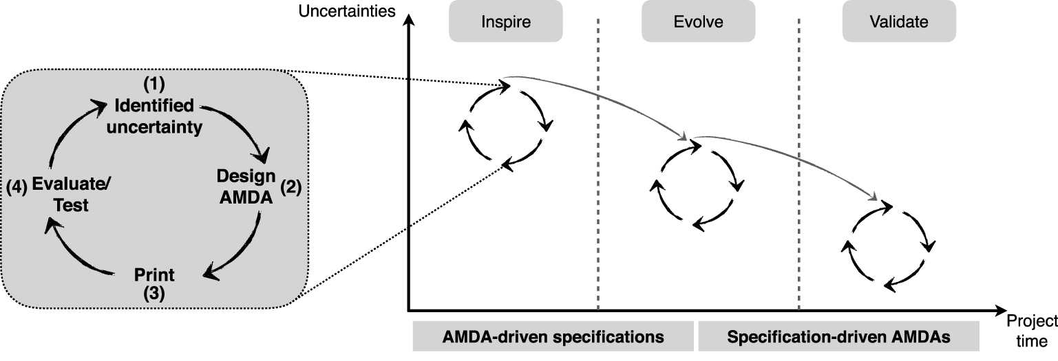
Figure 3. Design process with AMDA as a support to identify, explore and decrease AM-related uncertainties (inspired by Hartmann (Reference Hartmann2009)).
Drawing on the research of Hartmann (Reference Hartmann2009), the purpose of the AMDAs change as the product design evolves and uncertainties are reduced. Initially, AMDAs are used to explore ideas and design opportunities possible to realise with AM and to evaluate AM-related uncertainties coupled to these opportunities. This way, the AMDAs serve as an abstraction of the product in order to make it easier to measure (evaluate) by removing as many other uncertainties as possible. As uncertainties are resolved (and reduced), details of the design features are set and the AMDAs are used to evaluate more elaborate ‘embodiment solutions’. This way, the artefacts drive the design specification (AMDA-driven specification), building on what is learnt during previous iterations. As the design specification is set, the artefacts are used to validate the specification (specification-driven AMDAs).
4 Evaluating design uncertainties using AMDAs
To evaluate and exemplify the proposed AMDA design process, three cases of space applications are presented, one for each of Company A, B, and C. The product redesigned for AM by Company A was a rocket engine turbine manifold (Figure 4a). Utilising AM potentials, the redesign integrated a stator and manifold into one part. The process and material to be used were laser powder bed fusion (LPBF) and a nickel-based alloy, respectively. The product redesigned by Company B was a satellite antenna assembly consisting of a radiator, a bracket and a polariser (Figure 4b). The internal geometry of the polariser was kept according to an original design, but the part was integrated with the bracket to be manufactured in one piece instead of two. The radiator was excluded from the redesign. The process and material to be used were LPBF and an aluminium-based alloy, respectively. The part redesigned by Company C was a flow distributor for a satellite propulsion system (Figure 4c). The AM process and material to be used were electron beam powder bed fusion (EPBF) and a titanium-based alloy, respectively. All three companies used external AM suppliers for manufacturing.

Figure 4. Case examples redesigned for AM by the participating companies: (a) rocket turbine manifold with integrated stator, (b) satellite antenna assembly with integrated polariser and bracket, (c) satellite propulsion system component.
At the start of the research project, Company A already had a defined case concept and was in the embodiment design phase (cf. Ulrich & Eppinger Reference Ulrich and Eppinger2012). Company B and C entered the project with ideas of product applications to be redesigned for AM, but had not started concept development. Table 2 (next page) describes each of the cases with regard to its function and foreseen benefits of using AM. The critical features that were identified using the AMDA design process are also given, as are the associated uncertainties.
Table 2. Description of the case examples including the critical features that were identified and their related uncertainties

4.1 Case A
The integrated design implied that the roof of the manifold had to be self-supporting since access for support structure removal was limited or not possible. Due to subsystem interface requirements, walls with less than  $45^{\circ }$ inclination (as first recommended by the supplier) were needed. Limited possibility to inspect internal surfaces, uncertainty in buildability and ‘down-skin’ surface roughness, made the roof a critical design feature. Three main uncertainties were identified (A.1–A.3 according to Table 2). Three AMDAs were designed to assess the capability of the machine to build the roof (Figure 5, top), focusing on two aspects: (1) evaluate three different design solutions of the roof shape (uncertainty A.1), and (2) evaluate interaction with the recoater (uncertainty A.2). Three plates were built with artefacts in different orientation relative to the recoating direction (Figure 5, middle). The twin-arch concept was early discarded due to the need for support structure in the middle. The ‘angle’ artefacts were designed with wall angles between $24^{\circ }$ and $40^{\circ }$. The ‘radii’ artefacts were designed with wall angles of $45^{\circ }$ and radii between 1 mm and 10 mm. Evaluation of the printed AMDAs indicated that it was possible to use wall angles less than $45^{\circ }$, but also that the ‘down-skin’ surface roughness depended on angle, radius and orientation relative to the recoater. It was also seen that the wall thickness varied depending on the orientation on the plate. Considering the overall manufacturing outcome among the different shapes and orientations, the best solution was chosen to be the ‘angle shape’ with a wall angle well below $40^{\circ }$ (exact value cannot be disclosed).

Figure 5. Artefacts designed to test the machine capability (top) and built samples on the build plates (middle). CAD model of full-scale roof section (bottom left) and the printed section (bottom right).
To further evaluate manufacturability and interaction with the recoater, a larger roof section was extracted from the redesigned manifold (Figure 5, bottom left). The section was placed in the same orientation as intended for manufacturing of the complete manifold. The artefact printed successfully (Figure 5, bottom right), giving further confidence in the roof design and to proceed with the manufacturing of the complete manifold (not part of this study). The larger roof section is currently further used for evaluating different types of surface treatment methods (uncertainty A.4). The benefit of using AMDAs for the evaluation is that it is representative of the geometry and features of the actual manifold. Evaluation of these tests is still to be made.
To assess the impact of ‘down-skin’ surface roughness on fatigue properties (uncertainty A.3), AMDAs were designed resembling the roof geometry using a generic shape of a square diamond with wall angles of  $45^{\circ }$ and radius 4 mm. The geometry, test rationale and tested artefacts are shown in Figure 6 (top). Before testing, the average radius of the roof and reference radii were measured to 2.7 mm and 3.9 mm, respectively. Hence, there was an impact from the build process on dimensional accuracy of the roof. Visual inspection indicated a rougher surface on the roof radii compared to the reference. Five of the diamonds were tested under cyclic loading according to ASTM E466-15 standard (ASTM 2015). Loading was sinusoidal at 10 Hz with a load range aiming for failure at 10,000 cycles $(R=0.1)$. All samples were heat treated after removal from build plate. Three of the artefacts tested the tip radius (the roof), and two tested the vertical radius as reference. Preliminary test results are presented in Figure 6 (bottom), showing a strong dependence on fatigue life for the tested radii, with the roof having a life of roughly 1/3 of the reference. The results indicate an impact of geometry, surface roughness and material properties on the fatigue life. It is stressed that the number of samples is limited to draw general conclusions.

Figure 6. Geometry of diamond artefacts and the rationale for testing, indicating the roof radius (R1) and the reference radius (R2) (top left). Printed artefacts subjected to fatigue testing (top right) and results from testing (bottom).
4.2 Case B
Two main uncertainties were identified for the LPBF polariser (B.1 and B.2 according to Table 2). The internal surface roughness and its impact on radio frequency (RF) transmission performance (uncertainty B.1) was essential to evaluate in order to assess the feasibility of using AM in these types of applications. This was especially the case for the polariser design in Figure 4(b) due to difficulties with machining internal surfaces. During manufacturing planning, the product was oriented in order to avoid support structure within the polariser for this reason as well (Figure 7).

Figure 7. Orientation of assembly with polariser free from internal support structure.

Figure 8. Printed waveguides (top left) and the test set-up (top right). New antenna array designed for AM (bottom left) and one printed AMDA for RF test (bottom right).
Two AMDAs were designed in the shape of simple waveguides. One AMDA was printed in the vertical direction, and one was printed with an inclination of  $45^{\circ }$ (Figure 8, top left) to also test the impact of build orientation (uncertainty B.2). Both were then tested for RF performance (Figure 8, top right), and compared to a conventionally machined artefact of the same shape. Testing of transmission loss showed that the conventional part performed better than the AMDAs (as expected), but with the AMDAs performing better than expected. Return loss also showed better performance than expected for the AMDAs, but with higher losses than the conventional part (exact measurement cannot be disclosed). Explanations for the increased loss could be the surface roughness and imperfections in the connecting interfaces of the AM artefacts since these were not machined. It was concluded that the performance of the AMDAs indicate that the as-built surface roughness could be acceptable for specific frequency applications.
During manufacturing planning for the assembly design, it was however found that in order to avoid support structure internally in the polariser, its build orientation implied excessive use of support structure for the assembly as a whole (Figure 7). Based on the experience from designing the antenna assembly and testing of the AMDAs, Company B re-evaluated the use of AM in their applications. Another type of antenna was considered more suitable for AM, which was designed and printed (Figure 8, bottom left). The antenna was printed together with two new AMDAs for test of surface roughness impact on RF performance (Figure 8, bottom right). These new AMDAs were compared to a machined equivalent. Again, the AMDAs measured higher return loss than designed, resulting in an increased transmission loss as well. Compared with the machined equivalent, the AMDAs had only slightly larger losses. Repeatability and reproducibility were also encouraging since both AMDAs showed similar results (exact measurements cannot be disclosed). The conclusion was that LPBF is a viable production method for the tested frequency range polarisers in terms of loss performance. Redesign and optimisation of the AM design is, however, needed to improve the return loss performance to account for dimensional deviations in the LPBF process.
4.3 Case C
Weldability of the AM material was identified as the main uncertainty (uncertainty C.1 in Table 2) since the component has to be welded together with the piping of the propulsion system. The area for welding is shown in Figure 9 (top). To assess the weldability of the EPBF material, eight AMDAs in the shape of straight part-representative pipes were printed (Figure 9, bottom left). The pipes had different dimensions in order to evaluate different approaches for welding, including welding of as-built and machined surfaces. Initial weld tests were performed on pipes with as-built surfaces showing better results than expected, which was confirmed by subsequent X-ray (Figure 9, bottom right). Unfortunately, machining of the pipes for weld tests on machined surfaces was poorly done at a supplier. The pipes ended up not being concentric and could therefore not be used for testing. The results from the weld samples with as-built surfaces were however reassuring and gave confidence in the continued evaluation of using EPBF for manufacturing of flow distributors.

Figure 9. Detailed view of welding area (top). Printed AMDAs for welding and machining tests (bottom left) and X-ray of weld area (bottom right).
5 Analysis
Table 3 summarises the results for each of the examples. The role of each AMDA is defined, i.e., if the purpose was to inspire, evolve or validate design solutions, and whether the AMDA was used to drive or was driven by the design specification (refer to Figure 3). The outcome of the testing and the following activity is also presented.
Starting from a defined manifold concept, Company A identified the unsupported roof as a critical design feature with four related AM uncertainties. Initially, one type of AMDA was designed and printed in 33 examples to evaluate the geometrical limits of the self-supporting roof (uncertainty A.1) and the impact of build orientation on manufacturability (A.2). The evaluation of the AMDAs made it possible for the design team to define the geometry of the roof, hence evolving the manifold design. The larger roof section validated the manufacturability of the roof geometry, and gave confidence to proceed with manufacturing of a complete manifold to be used for testing and verification. The same AMDA (roof section) was subsequently used for testing of different surface treatments methods (A.4) in order to validate a suitable process for the manifold geometry (results from this evaluation are pending). Hence, this AMDA served two purposes. Last, the eight diamond AMDAs addressed the uncertainty of surface roughness impact on fatigue properties of the manifold geometry (A.3). Expecting that surface roughness would have impact on fatigue properties, the manifold was designed with this in consideration. Hence, the results did not impact the design, but indicated that surface roughness has significant impact on fatigue properties for the specific geometry. However, it was also expressed by the engineers that there is a need to continue to evaluate the usefulness of AMDAs purposely designed for material testing. ‘The [fatigue] diamonds were one step, but these could probably be developed to be more representative of the product’ as one member of the design team said. Hence, while the diamond was used to some extent to validate design assumptions, it was primarily used to inspire future use of such experimental artefacts. In conclusion, the initial roof geometry AMDA was used to drive the design specification, while the following roof section and diamond AMDAs were specification-driven in order to validate design choices and assumptions, and to inspire future designs of AMDAs for material testing.
Table 3. Summary of results from using AMDAs to evaluate identified design uncertainties related to the AM process. Evaluated uncertainties refer to Table 2

Both Company B and C started their development in the concept phase, which can be seen in how they utilised the AMDA design process. In comparison to Company A, both Company B and C initially used AMDAs to inspire design solutions utilising AM potentials. In the case of Company B, the waveguide AMDAs were used to evaluate the uncertainty of surface roughness (B.1) and build orientation (B.2) impact on RF performance. While the results from testing were promising with regard to RF performance using as-built surfaces, lessons learnt from the design process made the engineers reconsider what would be a suitable application for AM. Backed up with the test results, a redesign was made, and with that, new AMDAs (polarisers) specific for the new application. Testing of the polarisers indicated that the evolved design was better suited, but also that design optimisation of the new application is needed. Hence, the AMDAs used by Company B were in both cases driving the design specification.
The AMDAs designed by Company C in the shape of eight straight pipes evaluated the uncertainty of weldability (C.1) since welds were considered the most critical features of the flow distributor. The successful weld tests (although only on as-built surfaces) showed that the EPBF is a feasible manufacturing method for the application, but that further evaluation is needed. Hence, the AMDAs used by Company C will drive future design specifications. Figure 10 compares how the design process with AMDAs was practiced by the companies relating it to the general product development process (cf. Ulrich & Eppinger Reference Ulrich and Eppinger2012).

Figure 10. Comparison of how the companies used the AMDA design process during the development of each product example. Grey areas indicate in which phase of the development process the design teams were working. Each AMDA is defined as either used to drive or validate the design specification. Black arrows show work documented during the research process, dotted arrows show future work.
6 Discussion
The discussion is divided into four sections reflecting on AMDAs as part of the product development process, the nature of AMDAs in relation to prototypes, how AMDAs support AM process understanding, and finally generalisation and limitations.
6.1 AM design artefacts in the product development process
The three case studies exemplify the application of the AMDA design process in different phases of product development. In all three cases, the AMDAs were successful in reducing application-specific AM-related uncertainties. However, the process proposed in Figure 3 makes no distinction of how to utilise the process in different design phases. To further describe how the AMDA design process is part of a complete product development process, a generalised design process utilising AMDAs is proposed in Figure 11 by reflecting on the three cases.

Figure 11. Generalised design process with AM Design Artefacts.
For Company B and C, starting in the conceptual phase, the AMDAs were used to evaluate the feasibility of using AM for the application chosen as a candidate for AM. Hence, the fundamental question that dictated what to test was: Is AM suitable for this application? Concept designs were defined, and critical features and associated uncertainties were identified in order to answer the question. The outcome of testing the AMDAs provided sufficient confidence to decide on how to proceed (concept AMDA design loop in Figure 11). For Company B, an interesting turn of event was the realisation that the initial application was not suitable for AM, but that another application could be. The AMDAs hence provided inspiration for going back to candidate selection followed by a new concept development (illustrated by the double-headed arrows in Figure 11). AMDAs designed and tested for the new application subsequently showed feasibility for this new application, but also that further design optimisation was required. This would imply continuing to the embodiment/detail phase. In the Case of Company C, feasibility was shown, but insufficient testing implied a new concept AMDA design loop.
For Company A, working in the embodiment/detail phase, the general question that dictated what to test was: How should the manifold roof be designed to ensure manufacturability? The initial AMDAs were designed and built to answer this question, and consequently evolved the design of the manifold (embodiment/detail AMDA design loop in Figure 11). The design was subsequently validated with another AMDA design loop before confidence was sufficient to proceed with manufacturing of the complete manifold for testing and verification (shown in Figure 11 although this phase was not part of the study). One characteristic of DfAM that was pronounced in the case of Company A, was that the embodiment and detail design phases became intertwined as argued by Kumke et al. (Reference Kumke, Watschke and Vietor2016). The detailed design of the roof was necessary before the embodiment of the manifold could proceed. To illustrate this characteristic, the phases are merged in Figure 11. Another insight from all three cases is that they practiced Restrictive or Dual DfAM approaches (Laverne et al. Reference Laverne, Segonds, Anwer and Le Coq2015), focusing on the capabilities of the AM process, and the impact of process characteristics on performance and manufacturability. The Dual DfAM approach is especially pronounced in the case of Company A since they utilised the potential of AM to design the manifold to consist of only one part (part consolidation). Another activity that is part of a design process for AM is the selection of manufacturing process, given the multitude of AM processes available (Gibson et al. Reference Gibson, Rosen and Stucker2015). In the three case studies, the manufacturing process was already chosen by the companies, and this activity was therefore not explicitly covered by this study. It is however acknowledged in Figure 11. Also, implicitly implied in Figure 11 is that other design supports that are essential and available within a design team should be used during the development, e.g., DfAM tools.
6.2 Nature of AM design artefacts
The AMDA is complementary to the other three categories of ‘standard’ test artefacts commonly used in AM (benchmark artefacts, test coupons and travellers) in that it allows evaluation of application-specific part- and process-related uncertainties identified during the design process. For example, Moylan et al. (Reference Moylan, Slotwinski, Cooke, Jurrens and Donmez2014) suggest that standard benchmark artefacts should be designed to minimise interaction with the powder recoater to be easily built on several AM systems. While being useful for comparing and measuring AM processes, the drawback is that it does not provide engineers with sufficient information about how their specific part will interact with the process. AMDAs provide instant feedback and understanding of how a part or feature interacts with the chosen AM process, enabling reduction of design- and manufacturing-related uncertainties (as shown by the case studies in this paper). One engineer at Company A expressed this as: ‘In the design of each artefact, the question has always been “how relevant is this artefact in relation to the real component?”’. The design process described by Hartmann (Reference Hartmann2009) inspired the proposal of Figure 3. While the aim of Hartmann’s process (to design new products through the use of multiple prototypes) is rather different from the AMDA design process, the use of artefacts (prototypes) to drive and validate design specifications has been shown in a different context through this study. The outcome of evaluating AMDAs can be categorised according to this notion. AMDAs were shown to both drive and validate design specifications in the embodiment/detail phase, while they were exclusively used to drive the design specification in the concept phase. Furthermore, it was shown that AMDAs in concept design were used to either inspire or evolve design solutions, while in embodiment/detail design they were used to evolve or validate design choices and assumptions. In addition, the diamond artefact served as inspiration for future designs of AMDAs aimed at material testing.
Another distinction from Hartmann’s design process is that the number of artefacts does not seem to be relevant. After an uncertainty was identified, the use of few or several AMDAs provided sufficient information to draw conclusions and make decisions to proceed with the design. For example, to resolve uncertainty A.1 and A.2, Company A manufactured 33 artefacts that were evaluated. In comparison, Company B only needed two artefacts to resolve uncertainty B.1 and B.2 sufficiently to proceed. This confirms previous research that focused artefacts (prototypes) are used, and are valuable, for resolving specific uncertainties related to design and manufacturing (Elverum & Welo Reference Elverum and Welo2015; Menold et al. Reference Menold, Jablokow and Simpson2017). The AMDAs are one manifestation of critical function prototypes proposed by Elverum & Welo (Reference Elverum and Welo2015) since they are physical focused artefacts used to evaluate specific design-related uncertainties (Ulrich & Eppinger Reference Ulrich and Eppinger2012; Elverum & Welo Reference Elverum and Welo2015). However, Elverum & Welo (Reference Elverum and Welo2015) argue that these types of prototypes are more beneficial when phenomena are well understood and there is previous experience that can be used. In the context of this study, value was shown for using critical function prototypes for exploration as well. It is stressed that the AMDA design process is an iterative experimental design approach (Thomke Reference Thomke1998) as indicated by step 4 in the process (evaluate/test). If the results from the evaluation/testing are satisfactory and identified uncertainties have been resolved, the design process proceeds. If the results are not satisfactory and uncertainties are not sufficiently resolved a new AMDA design loop might be necessary.
By nature, AMDAs focus on exploring known unknowns (Sutcliffe & Sawyer Reference Sutcliffe and Sawyer2013) and no evidence was found that unknown unknowns could be derived. However, since AMDAs are manufactured using the same process and material as the product being designed, they should be categorised as high-functional prototypes with regard to the uncertainty being explored (Jensen et al. Reference Jensen, Elverum and Steinert2017). Jensen et al. (Reference Jensen, Elverum and Steinert2017) argue that high-functional prototypes have the potential of exploring unknown unknowns with regard to, for example, mechanical insights. Since AM materials and processes are not fully understood (Lewandowski & Seifi Reference Lewandowski and Seifi2016), purposely designed AMDAs could possibly be used to explore unknown failure modes for AM materials, or process-related phenomena. From this perspective, AMDAs require further use and testing in order to investigate their ability to explore unknown unknowns, especially with regard to AM materials and process characteristics.
6.3 AM design artefacts support AM process understanding
Throughout this research, it was clear that engineers face many uncertainties when they design products for AM. Within the scope of the case studies, in total, seven AM-related uncertainties were identified as critical to explore in order to make relevant decisions concerning manufacturability or design feasibility. Interestingly, the nature of these uncertainties is not unique for these case studies, but have been described in previous literature. For example, impact of surface roughness on performance (Snyder et al. Reference Snyder, Stimpson, Thole and Mongillo2015) or impact of surface roughness on fatigue properties (Beretta & Romano Reference Beretta and Romano2017). A multitude of guidelines for designing products for AM have been proposed in recent years. However, they are still evolving (Schmelzle et al. Reference Schmelzle, Kline, Dickman, Reutzel, Jones and Simpson2015; Thompson et al. Reference Thompson, Moroni, Vaneker, Fadel, Campbell, Gibson and Bernard2016) and literature suggests that there is a difficulty in transferring these guidelines into industry (Leutenecker-Twelsiek et al. Reference Leutenecker-Twelsiek, Klahn and Meboldt2016). This could be one reason for designers identifying uncertainties that have already been identified and explored by others. Another is the fact that engineers need to know how uncertainties relate to their specific applications. One example from the case studies is the uncertainty of recoater interaction (A.2). While it is known that recoater interaction is important to consider in PBF processes (e.g., Salmi et al. Reference Salmi, Calignano, Galati and Atzeni2018), the design team at Company A still needed to understand how it would impact their design of the manifold roof. As one design engineer at Company A expressed it: ‘I need machine-specific limitations to work with. General rules are maybe good, but it is the machine-specific [rules] that are important’. In the case of Company A, process experience of the supplier proved to be essential during the development since they were able to provide feedback on the design with regard to buildability and risks, and to suggest design changes. One manufacturing engineer from the supplier expressed that ‘not many people design for the process, although this is improving, [but] they design for function’, stressing the need to understand what the capabilities of the process are. Designing products for AM hence requires engineers to understand the process, and AM knowledge is therefore an important aspect. Obviously, the level of AM knowledge within a design team dictates what the perceived uncertainties are. As indicated by Pradel et al. (Reference Pradel, Zhu, Bibb and Moultrie2018b) designers rely on their own experience and ‘learning by doing’ when designing products for AM. This highlights an important distinction between the proposed AMDA design process and general DfAM guidelines. The AMDA process supports design teams with a systematic approach to acquire AM understanding, while also developing products for AM. The AMDA design process proposed in Figure 3 (and generalised in Figure 11) provides an approach to assess AM-related uncertainties that are encountered during product design for AM. It is inspired by observations that artefacts are, in fact, used during the design and evaluation of AM parts, but that no systematic process has been described for this purpose. As with prototypes in general, the study shows that AMDAs facilitate learning, communication (especially with suppliers), and decision-making (Ulrich & Eppinger Reference Ulrich and Eppinger2012; Lauff et al. Reference Lauff, Kotys-Schwartz and Rentschler2018).
In summary, in relation to prototyping literature, AMDAs are one manifestation of critical function prototypes that focus on critical functions or features of an AM product. The term AM design artefact has been chosen to distinguish them from the general term prototype, which can be ambiguous (Schrage Reference Schrage1993), to better represent its use and purpose. Furthermore, the unique characteristic of AMDAs are that they are built using the same process and material as the product being developed, while the product is being developed. This is enabled by the rapid manufacturing capability of AM processes, and therefore facilitates concurrent development of product and AM process understanding. An important aspect of the AMDA design process is hence to support the need to concurrently develop AM products and AM process understanding. This is emphasised in Figure 11 by the parallel execution of product development and manufacturing.
6.4 Generalisation and limitations
The AMDA design process and its purpose, i.e., to identify and evaluate application-specific part- and process-related uncertainties, is in itself generalisable to other contexts than that studied in this paper. Other industries and projects can utilise the iterative design approach to design products and develop AM process understanding. Since building process understanding is an important aspect of the approach there is also a responsibility on design organisations to capture gained knowledge in order for future projects to utilise what has previously been learnt. A topic for future research is therefore how process-specific AM knowledge can be captured efficiently to successively increase organisational DfAM understanding. While PBF processes were studied in this paper, the approach should be applicable for other AM processes as well since its nature is to focus on the specific characteristics of the process being used coupled to the product being developed. Other researchers are invited to further explore the use of AMDAs as a support for DfAM, and how AMDAs can facilitate the building of process understanding to further speed up the adoption of different AM technologies.
A limitation of this study is that none of the studied cases went through several design phases, and the number of sequential artefacts were limited to two at most. However, it can reasonably be argued that AMDAs for driving the design specification are dominant in the conceptual phase, and specification-driven artefacts are dominant in the embodiment/detail phase. Similarly, inspiration was mainly sought for earlier in the design process, while design evolution and validation were in focus later on, although clear boundaries cannot be drawn (as illustrated in Figure 11). Future research should focus on using this design process through a complete product development process. Another limitation is that AMDAs are very specific for the design being developed and as such a support for the designer to understand if a concept is feasible. They provide DfAM understanding for design engineers, but they do not provide statistical data to be used in, for example, simulations. AMDAs are useful for identifying and evaluating uncertainties for a specific application because the process and product are intertwined. To generalise this further, more rigorous parametric studies are needed. For example, the use of AMDAs might facilitate the design of company-specific benchmark artefacts that can be used to perform such parametric studies. This could in-turn result in company-specific design guidelines for products or product families. The use of AMDAs to evaluate part-specific mechanical properties was touched upon in this study through the diamond artefacts design and tested by Company A. Such artefacts could potentially render statistical data to be used in, for example, life analysis, but more research is needed to explore the usefulness of AMDAs for such purposes.
7 Conclusions
In order to design a part that is suitable for a chosen AM process, engineers need to understand the process capabilities (both possibilities and limitations), as well as consider availability and capabilities of post-AM processes (e.g., surface finishing). However, engineers experience several uncertainties when designing parts for AM, impeding its implementation. Identifying and evaluating part- and process-related uncertainties is therefore central in the adoption of AM. Development of AM process understanding, utilising available knowledge within design teams and AM users, is in this context essential. Valuable understanding can be built through ‘learning by doing’ and efficient communication with the AM user (either in-house or external). Purposely designed AMDAs can be used to support this development of understanding, and to facilitate communication. Furthermore, uncertainties related to design, manufacturing, material characteristics and post-processes can be explored. The benefit is that smaller artefacts and larger quantities can be used to assess different design solutions, with less need for expensive manufacturing of complete parts. The contributions of this paper are: (i) a design process where AMDAs are iteratively used as support in evolving and defining an AM part specification, (ii) an example of how DfAM is practiced in industry and of typical AM uncertainties that are encountered and addressed in making design decisions, and (iii) an example of how collaborative research can facilitate new knowledge for both industry and academia. The level of AM knowledge varies among practitioners, and consequently so do the uncertainties that arise. The process of working with AMDAs focuses on evaluating identified uncertainties, and can be used for the most open design questions currently asked by a design team. The practical implication of this research is therefore the concretisation of a DfAM process for engineers to use and adapt according to existing AM knowledge in order to evolve it further.
Acknowledgments
The authors would like to thank the participating companies for providing cases to study and in enabling the interactive collaboration that made this research possible. They would also like to thank their fellow researchers at Luleå University of Technology and Chalmers for their work during the research process. A special thank you goes to professor Olaf Diegel for an introductory course in DfAM.
Financial Support
This research was funded through the LTU Graduate School of Space Technology, the EU project RIT (Space for Innovation and Growth), and the Swedish National Space Agency through NRFP (Swedish National Space Research Programme).
Appendix
Table 4 is a summary of the number of participants and their roles from companies and university at each workshop (WS). Note that Company C was not able to participate during WS 3 and 5. The five main workshops (WS1-5) were held as joint workshops. In addition, intermediate workshops were held at each company specifically.
Table 4. Summary of workshops


 Open access