


1. INTRODUCTION
At the moment, research and development of Autonomous Underwater Vehicles (AUVs) has become of special strategic and economic significance. During extended AUV missions, additional aided navigation methods are needed to correct the navigation errors of Inertial Navigation Systems (INS), which increase with time. At present, radar, laser and sonar are deployed on AUVs to establish the underwater navigation system. However, similar to radar navigation close to the surface, laser or active sonar transmission (underwater terrain could be measured for aided navigation) can affect the covertness of AUVs. Gravimetry is not emanative, and not easily detected and interfered with. Gravity-aided navigation is stable and passive and thus is appropriate for covert underwater navigation. In the past few years, gravity/gravity gradient-aided underwater passive navigation systems have been established on AUVs or submarines to limit INS error accumulation (Affleck and Jircitano, Reference Affleck and Jircitano1990; Goldstein and Brett, Reference Goldstein and Brett1998; Hays, Reference Hays2002; Jircitano et al., Reference Jircitano, White and Dosch1990; Moryl et al., Reference Moryl, Rice and Shinners1998; Rice et al., Reference Rice, Mendelsohn and Aarons2000; Rice et al., Reference Rice, Kelmenson and Mendelsohn2004; Vajda and Zorn, Reference Vajda and Zorn1998; Wang and Bian, Reference Wang and Bian2008). Gravimeters and gradiometers were adopted to compensate the INS (Jekeli, Reference Jekeli2006; Moody and Paik, Reference Moody and Paik2004). In addition, gravity and gravity gradient have been used for underwater object detection which is a significant subject in the field of underwater navigation (Wu and Tian, Reference Wu and Tian2010; Wu et al., Reference Wu, Tian, Ma and Tian2010b; Wu et al., Reference Wu, Ke, Hsu, Fang, Xiong and Wang2013).
Researching a precise location algorithm is one of the most important key technologies of underwater navigation systems. Several methods have been developed for gravity matching navigation. Kalman filters were designed to estimate the state parameters of gravity/gravity gradient/geomagnetic aided navigation systems (Wu et al., Reference Wu, Gong, Cheng, Ma and Tian2007; Wu et al., Reference Wu, Ma and Tian2010a; Wu et al., Reference Wu, Tian, Ma and Tian2011; Xu, Reference Xu2005; Zhang et al., Reference Zhang, Chen, Sun, Yan and Yang2004b; Zheng et al., Reference Zheng, Wang, Wu, Chai and Wang2013). The Iterated Closest Contour Point (ICCP) algorithm was constructed for vehicle localisation in gravity maps (Bishop, Reference Bishop2002; Deng et al., Reference Deng, Ge, Guan and Han2010; Kamgar-Parsi and Kamgar-Parsi, Reference Kamgar-Parsi and Kamgar-Parsi1999). The Terrain Contour Matching (TERCOM) algorithm was explored for terrain matching-aided navigation at first (Golden, Reference Golden1980; Siouris, Reference Siouris2004), but nowadays the TERCOM algorithm is widely employed for gravity matching navigation. With the TERCOM algorithm, the trajectory with a real-time sequence of gravity measurements is taken to make correlation analysis with the stored gravity maps. Then the optimal matching trajectories are obtained and used to correct the INS (Figure 1).

Figure 1. Principle of the TERCOM matching algorithm (Wang et al., Reference Wang, Wang, Fang, Chai and Zheng2012).
Conventional TERCOM methods based on pattern or image matching are widely used in terrain-aided navigation. Remote sensing devices such as active sonar, radar, and Charge-Coupled Device (CCD) cameras can be utilised to look around and typically provide many simultaneous measurements, either a two dimensional (2D) image or a one-dimensional (1D) profile which can be used for matching (Cowie et al., Reference Cowie, Wilkinson and Powlesland2008; Zhang et al., Reference Zhang, Chen, Sun, Yan and Yang2004a). In contrast, a challenging aspect of gravity pattern matching is that nowadays gravimeters can measure the field only in-place, and thus provide only one measurement at a time. Therefore, the traditional 2D pattern or image matching-based TERCOM methods cannot be employed without modification and a novel pattern matching method for gravity aided navigation needs to be explored.
With the original TERCOM algorithm, after passage the gravity measurements over a period of time were collected, then the gravity patterns were constructed based on the gravity measurements and the absolute INS indicated positions of points in the trajectory. The gravity patterns in straight lines were taken into the correlation calculations with the gravity maps in the area, so the matching trajectories which were parallel to the INS trajectories could be obtained. The original TERCOM algorithm can work stably and effectively as long as the INS quality is good enough. However, the vehicle must move with constant speed along a straight line (the trajectory is not strictly required to be parallel to one of the database axis directions) during each TERCOM update period (Yoo et al., Reference Yoo, Lee, Lee, Park and Kwon2012). So only limited manoeuvring in operation is allowed by the original TERCOM algorithm. More importantly, when the INS-indicated positions diverge from the actual trajectory or direction due to the accumulated position errors, huge position errors and even false navigation results may be produced. Apparently, the conventional TERCOM algorithm cannot meet the needs of various nonlinear trajectories in practical navigation. Some modified TERCOM algorithms were developed in which translation and rotation were employed to improve the matching trajectories, but their performance in complicated curving trajectories which are common in practice was not impressive (Wang et al., Reference Wang, Zhang, Yang and Tian2010; Wang et al., Reference Wang, Wang, Fang, Chai and Zheng2012; Yoo et al., Reference Yoo, Lee, Lee, Park and Kwon2012). An improved TERCOM positioning method using relative position offsets from the INS was proposed for terrain-aided AUV navigation and obtained better performance (Ånonsen, Reference Ånonsen2005; Reference Ånonsen2010).
In this paper, a Relative Positions-Constrained pattern Matching (RPCM) method for underwater gravity aided inertial navigation is presented, which is an improved form of TERCOM. In this method the gravity patterns are constructed based on the relative positions of points in a trajectory, which are calculated by INS indications. Then the gravity patterns are taken into the correlation calculation with the stored gravity maps. The accumulated errors of INS indicated positions are cancelled in the relative positions and gravity patterns. Therefore, these new constructed gravity patterns are more accurate and reliable so the process of matching can be constrained; the probability of mismatching can also be reduced. The principle of the RPCM method is described in Section 2. A simulation analysis was performed in two gravity maps from different areas located in the South China Sea to analyse and verify the performance of the proposed RPCM method in Section 3. Finally, Section 4 gives conclusions.
2. THE RELATIVE POSITIONS-CONSTRAINED GRAVITY PATTERN MATCHING METHOD
When the AUV is in motion, gravity measurements g i (i = 1, 2, 3, …) at the points p i(x i, yi) (i = 1, 2, 3, …) along the trajectory can be obtained with the on board gravimeter. Here p i(x i, yi) are the actual positions of the AUV, and the corresponding INS-indicated positions are p iINS(x iINS, yiINS). High-precision INS can give continuous accurate positions to begin with, but the accumulated position errors are still unacceptable after a long period underway. Certainly, there are drift errors between p i(x i, yi) and p iINS(x iINS, yiINS). The position error of INS increases slowly with time, but does not increase suddenly and rapidly in a short period. So in a period of time the relative positions between p iINS and p jINS can be regarded as accurate and reliable. For example, after 20 hours' sailing the positions indicated by the INS with 0·01 deg/hr gyroscope bias (p iINS(x iINS, yiINS)) may be wide apart from the actual positions (p i(x i, yi)), but the relative positions between two points just passed in a few minutes can be more accurate and reliable.
Consequently, the relative positions can be found as follows:
 $$\left\{ {\matrix{ {\Delta {x_{ij}} = {x_j} - {x_i} \approx x_{_j} ^{INS} - x_{_i} ^{INS}} \cr {\Delta {y_{ij}} = {y_j} - {y_i} \approx y_{_j} ^{INS} - y_{_i} ^{INS}} \cr}} \right.$$
Based on this assumption, after the passage the gravity pattern/image S in a period of time can be constructed, as can be seen in Figure 2. In this image S, the relative positions (Δx ij, Δy ij) between p i and p j are calculated from INS indicated positions with Equation (1), although the actual values of (x i, yi) or (x j, yj) themselves are unknown. From Equation (1) it can be seen that the accumulated errors of INS indicated positions are cancelled in the relative positions (Δx ij, Δy ij). Also, in this image the positions without measurements are signed with invalid data that would not be used in the following correlation calculation.

Figure 2. Construction of gravity pattern/image S.
The correlation coefficients between gravity map P and the gravity pattern/image S which can be completed only after the passage would be calculated as follows:
 $$COEFS = COR({S_{m^*n}},{P_{M^*N}})$$
where S is a m*n matrix, P is a M*N matrix, so the size of correlation coefficients matrix COEFS is (M − m + 1)*(N − n + 1). COR is the correlation algorithm, Mean Absolute Difference algorithm (MAD) and Mean Square Difference algorithm (MSD) can be chosen as the algorithm. The MAD and MSD algorithms have proven to be an effective correlation scheme and their definitions are as follows:
 $$MAD(x,y) = \displaystyle{1 \over {M^*N}}\sum\limits_{u = 0}^{M - 1} {\sum\limits_{v = 0}^{N - 1} {\vert S(u,v) - P(x + u,y + v)\vert}} $$
 $$MSD(x,y) = \displaystyle{1 \over {M^*N}}\sum\limits_{u = 0}^{M - 1} {\sum\limits_{v = 0}^{N - 1} {{{[S(u,v) - P(x + u,y + v)]}^2}}} $$
The minimum value of coefficients can be found:
 $$min\_coefs = \min (COEFS)$$
So the minimum value of coefficients identifies the matching position in the gravity map which is considered to be the optimal matching position.
From the above it can be seen that the RPCM method here and the TERCOM method are both positioning methods based on a correlation calculation with the stored maps. In our proposed method the gravity patterns are constructed based on the relative positions of points in the trajectory, which are calculated by INS indicated positions. The accumulated errors of INS indicated positions are cancelled in the relative positions and gravity patterns, so the gravity patterns are in better agreement with the various actual trajectories. Therefore, these new constructed gravity patterns are more accurate and reliable so the process of matching can be constrained, and higher position accuracy may be achieved by the RPCM method in underwater gravity aided inertial navigation. Actually, although the shapes of trajectories can be recovered better by gravity patterns with the RPCM method, essentially it is just a positioning method in which mostly only position errors but not velocity or attitude errors were included and could be reduced. The effect of attitude or velocity errors that cannot be corrected in the TERCOM method also cannot currently be entirely cancelled by using the proposed method.
The flow chart of the RPCM method is presented in Figure 3.
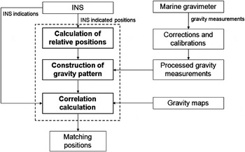
Figure 3. Flow chart of relative positions-constrained gravity pattern matching (RPCM) method.
From this figure it can be found that the proposed RPCM method for underwater gravity-aided inertial navigation can be described as follows.
Firstly, the relative positions of the points in a trajectory are calculated from the INS indicated positions. The relative positions are prepared to construct the new gravity patterns in which the accumulated position errors of INS are cancelled. They are different to the gravity profiles in the traditional TERCOM algorithm that are formed from absolute INS indicated positions.
Secondly, gravity patterns in a period of time are constructed with the calculated relative positions and the processed gravity measurements from the gravimeter. In practice, the influence of temperature, sea conditions and instruments should be considered such that the gravity measurements from the marine gravimeter cannot be used directly for gravity-aided navigation, so several corrections and calibrations must be done with the data. After the Eötvös correction (The Eötvös effect is the change in perceived gravitational force caused by the change in centrifugal acceleration resulting from eastbound or westbound velocity) and some processing including gravity base point comparison, gravimeter hysteresis effect correction, gravimeter zero point draft correction and vehicle's draft of water correction et al, the processed gravity data which fits the requirement of gravity aided navigation is ready for use.
Then the correlation coefficients between gravity maps and the constructed gravity patterns are calculated. Finally, the extreme value of coefficients identifies the optimal matching positions in the gravity maps.
3. SIMULATION RESULTS AND DISCUSSION
A simulation was performed to verify the proposed RPCM method performance. A gravity anomaly map P 1 which is located in the South China Sea area was chosen for simulation. The 2D and 3D views of the map are demonstrated in Figure 4. The size of map is 1024 × 1024 nautical miles (nm) and the resolution is 2 nm in both x and y directions. The gravity values in the map are gravity anomalies, and their statistical values are given in Table 1, where STD is standard deviation and RMS is root-mean-square.

Figure 4. Gravity map P 1 located in South China Sea.
Table 1. Statistical Values of Gravity Anomalies in gravity map P 1 (unit: mGal).

3.1. Individual trajectory test
A trajectory with the gravity measurements on it is illustrated in Figure 5. In this test the actual trajectory was designed as a slight curved line as this is common in practice. During the period of this trajectory, the INS drift was only presented in the y direction that led to the accumulated position errors just in this direction. As a result the INS-indicated positions were in a rectilinear trajectory. As the INS-indicated positions were in a rectilinear trajectory, the TERCOM method can be employed conveniently to make the correlation calculation and obtain a matching trajectory that can be taken to compare with the RPCM method. The curvature of the actual trajectories is much smaller as can be seen in Figure 6(a) than it looks in Figures 5 and 6(b), because Figures 5 and 6(b) are partially zoomed in and stretched in the north-south direction for the effect of display (the size of Figure 5 is 600 × 30 nm, and Figure 6(b) is nearly 800 × 160 nm). Here the gyroscope bias of the INS is 0·01 deg/hr, the velocity component in the x direction is 2 knots every sample time. A noise model was designed based on the data from a true gravity sensor so that measurement noises are added in the gravity measurements. The MSD algorithm was chosen for the correlation calculation (COR). Compared with TERCOM, in the RPCM method the gravity pattern/image S is constructed based on the relative positions as shown in Figure 5. The accumulated errors of INS indicated positions are cancelled in the relative positions and gravity patterns. So the positions of points in a trajectory can be recovered better with the RPCM method even though the actual effects of attitude errors were not cancelled out in this solution as in the TERCOM method.

Figure 5. A trajectory and the gravity pattern/image S.

Figure 6. INS indicated and matching trajectories (a) Trajectories in the map P 1; (b) Partial enlarged drawing.
In Figure 6 the one-time matching results of an individual trajectory test of TERCOM and RPCM position solutions shows that not only the shape but also the matching positions of the trajectory by RPCM are in better agreement with the actual trajectory. Obviously a higher position accuracy is achieved by the proposed RPCM method. In this test the size of gravity pattern/image S is 300 × 15 grids and the size of gravity map P 1 is 512 × 512 grids (2 nm/grid), so the correlation coefficients matrix COEFS is a 213 × 498 matrix - an image of it is presented in Figure 7. The minimum value of coefficients is 0·6438 that identifies the optimal matching position in the gravity map.

Figure 7. An image of correlation coefficients matrix COEFS.
3.2. Sets of trajectories test
Six sets of trajectories were simulated to test the two positioning methods: RPCM and TERCOM. In every set there are 100 trajectories of curved lines that have the same shape but different stochastic start points. From set No. 1 to 6 the degree of curvature of trajectories in every set increases. Here, the MAD and MSD algorithms were chosen for the correlation calculation (COR), also the same level of noise as in true measurement data were considered in the gravity measurements. The gyroscope bias of the INS and the vehicle speed component in the west-east direction are the same as the test in Figure 6. A successful matching is defined as that where the position error is smaller than a threshold. Here the matching success rate was calculated when the threshold was assigned as 1·414 nm. After the test matching, success rates and average position accuracies of RPCM and TERCOM can be calculated for every set of trajectories. The statistical results are presented in Tables 2 and 3.
Table 2. Matching Success Rates and Average Position Accuracies of RPCM and TERCOM Methods (MAD).

Table 3. Matching Success Rates and Average Position Accuracies of RPCM and TERCOM Methods (MSD).

It can be seen from Tables 2 and 3 that, from set No. 1 to 6 the matching success rates of TERCOM decrease rapidly, they are less than 34% for MAD and no more than 28% for MSD all the time. Meanwhile the average position accuracies of TERCOM get worse and worse, even the best accuracy is 1·97 nm for MAD and 2·38 nm for MSD.
However, in strong contrast the matching success rates and average position accuracies of the RPCM method perform excellently and remain stable throughout. The matching success rates are higher than 90% for MAD and higher than 96% for MSD, the average position accuracies are better than 0·20 nm for MAD and better than 0·08 nm for MSD during this simulation.
It can also be seen from the curves of matching success rates and average position accuracies in Figure 8 that distinctly improved matching success rates and position accuracies can be gained by this proposed RPCM method. In particular, when the degrees of curvature of trajectories are bigger, the advantages of the RPCM method over the traditional TERCOM method are more obvious. Thus the shapes of trajectories are not restricted with the proposed RPCM method.

Figure 8. Curves of matching success rates and average position accuracies of RPCM and TERCOM.
To verify the performance of the proposed RPCM method in different environments, another gravity anomaly map P 2 from a different area is taken to construct the same test. The size and resolution of the map P 2 are the same as the map P 1 but the features are quite different, as is illustrated in Figure 9 and the statistical values are given in Table 4.

Figure 9. Gravity map P 2 located in the South China Sea.
Table 4. Statistical Values of Gravity Anomalies in gravity map P 2 (unit: mGal).

Similarly, six sets of trajectories are simulated to test the RPCM and TERCOM method. The parameters are assigned as the same values as before. The resulting curves of matching success rates and average position accuracies are presented in Figure 10. Again, compared with TERCOM, obviously better matching success rates and position accuracies can be obtained by using the RPCM method.

Figure 10. Curves of (a) matching success rates and (b) average position accuracies of RPCM and TERCOM (with gravity map P 2).
Therefore, with the higher performance in matching success rates and position accuracies, the proposed RPCM method should be preferable in practical navigation.
4. CONCLUSION
A Relative Positions-Constrained pattern Matching (RPCM) method for underwater gravity-aided inertial navigation is proposed in this paper. The gravity patterns are constructed based on the relative positions between points in a trajectory, which are calculated by INS indicated positions. In these patterns the accumulated position errors of INS are cancelled and removed. Thus the new constructed gravity patterns are more accurate and reliable, the process of matching can be constrained, and the probability of mismatching can also be reduced. Simulation results show that the performance, including matching success rate and position accuracy, is highly improved with the RPCM method. However, the effects of attitude or velocity errors cannot currently be entirely cancelled by using the proposed method.
With the RPCM method the shapes of trajectories are not restricted as in traditional TERCOM methods so the novel method proposed in this paper is preferable in achieving the practical requirements of marine gravity-aided navigation. With this method the results of navigation may be in better agreement with the actual positions. Therefore, the accuracy and reliability of gravity-aided navigation would be improved.
In future research, more data from the true gravity sensors should be included in the simulations. The performance of gravity-aided inertial navigation in different environments (on surface or underwater) should also be investigated in a real marine test. Furthermore, present and future underwater INS/gravity integrated navigation systems would be supported and benefit from this research.
ACKNOWLEDGEMENT
The authors would like to thank the reviewers who provided comments that substantially improved this paper.
FINANCIAL SUPPORT
This research was supported by National Natural Science Foundation of China (Grant No. 41321063, 41104050, 41374086, 41204018 and 41274084), and Chinese Academy of Sciences International Partnership Program for Creative Research Teams (CAS/SAFEA) (Grant No. KZZD-EW-TZ-05).


