I. INTRODUCTION
Cellular phones and smartphones are communication tools that can be easily used anytime and anywhere, including in noisy environments. When a user is talking over the telephone in a noisy environment, his/her voice sent to call partner on the other end of the line (sending voice) mixes with the surrounding noise and becomes difficult for the call partner to hear, and the voice that is sent by the call partner (received voice) is buried by the noise surrounding the user. However, various speech technologies for improving the quality of the received voice have been developed and installed in mobile terminals. For example, a noise suppression technology that suppresses only the noise from the sending voice, with which the noise mixes, to improve voice quality has been developed [Reference Sugiyama and Miyahara1]. In addition, a voice enhancement technology that emphasizes the call partner's voice according to the volume and type of surrounding noise in noisy environments such as station platforms has been developed and installed. Furthermore, a speech rate conversion technology that slows the fast voice of the call partner while maintaining voice quality has been developed and installed.
We first explain the trends and technical features of voice enhancement technologies for improving the quality of the received voice according to the usage environment of the mobile terminal in Section II and those of speech rate conversion technologies in Section III. We then explain the implementation of the algorithms of our proposed technologies in mobile terminals in Section IV and explain other technologies for improving the quality of the received voice in Section V. Finally, we explain future applications of the speech technologies in Section VI.
II. VOICE ENHANCEMENT TECHNOLOGY
It is generally known that the quality of received voice is deteriorated by the noise or the reverberation generated in the user environment or the call partner's environment, and information compression according to audio coder-decoder (CODEC) when talking over the telephone with the mobile terminals. However, various speech technologies for improving the quality of the received voice have been developed and installed in mobile terminals. We give a general overview of several speech technologies for improving the listenability of received voice on mobile terminals: noise suppression technology, reverberation suppression technology, voice enhancement technology for audio CODEC and voice enhancement technology to surrounding noises.
A) Noise suppression technology
When a call partner is in a noisy environment, it may become difficult for the user to hear the received voice due to the surrounding noise. Therefore, noise suppression technologies for suppressing only the noise from the received voice, with which the voice and the noise mix, to improve voice quality have been developed.
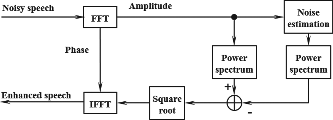
The noise suppression technologies are classified into the method with multiple microphones, and the method with single microphone. As a fundamental technology for suppressing the noise with single microphone, spectral subtraction method was proposed [Reference Boll2]. Fig. 1 is the block diagram of spectral subtraction method. With this method, noise components are suppressed by deducting the estimated noise spectrum from the input spectrum in a frequency domain. However, the noise components may remain because of the error of the estimated noise spectrum, and residual noise appears and disappears, as a result, it is easy to cause unpleasant sound called musical noise.

Fig. 1. Block diagram of spectral subtraction method.
As a technology for maximizing signal-to-noise ratio (SNR) that is power ratio of voice and noise and improving amount of noise suppression, minimum mean-square-error short-time spectral amplitude (MMSE-STSA) method was proposed [Reference Ephraim and Malah3]. Fig. 2 is the block diagram of MMSE-STSA method. In this method, the voice spectrum is obtained by applying the gain to the input spectrum. The gain is calculated by minimizing the mean square error between the voice spectrum obtained from input and estimated noise and the voice spectrum obtained by applying the gain to input spectrum in the condition of assuming the independence of the voice and the noise. The error of the voice spectrum can be evaluated by using a posteriori SNR (the ratio of the estimated voice power and the estimated noise power) and a priori SNR (the ratio of the input signal power to the estimated noise power). With this method, the amount of noise suppression becomes higher than those of above spectral subtraction method because of maximizing the power ratio of voice and noise. In addition, the power of the musical noise caused by this method is lower because of restoring the voice without deducting the estimated noise.

Fig. 2. Block diagram of MMSE-STSA method.
B) Reverberation suppression technology
When a call partner is in a narrow room, it may become difficult for user to hear the received voice because the partner's voice mixes with the reverberant sound that is sound to which the partner's voice reflects in the walls and ceiling. Therefore, reverberation suppression technologies for suppressing only the reverberant sound from the received voice, with which the voice and the reverberant sound mix, for improving voice quality have been proposed.
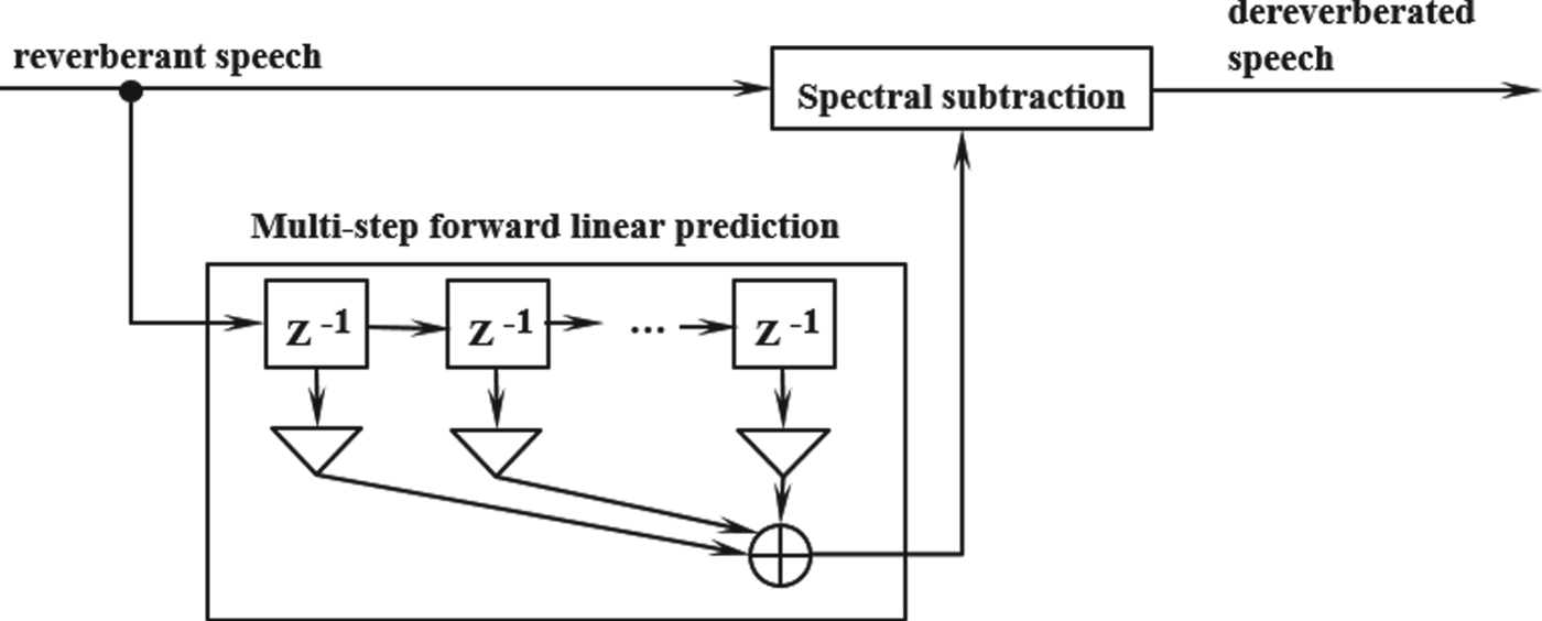
The reverberation suppression method that uses multi-step linear prediction in the time-domain has been proposed [Reference Kinoshita, Nakatani and Miyoshi4]. The effect of decreasing the reverberation time and that of improving the voice recognition rate by reverberation suppression are shown. Fig. 3 is the block diagram of the reverberation suppression method. With this method, the reverberation components are estimated from the reverberant speech signal by the linear prediction, and the reverberation components are suppressed using the spectral subtraction method. This method has been put to practical use as a plug-in feature for audio editing software [Reference Kinoshita5].

Fig. 3. Block diagram of the reverberation suppression method.
C) Voice enhancement technology for audio CODEC
About the voice enhancement for audio CODEC, the technologies that emphasize the formant and the pitch for a voice deteriorated by quantization noise according to the coding have been put to practical use until now.
Voice enhancement technologies for audio CODEC that emphasize formant and pitch have been applied to the algebraic code excited linear prediction (ACELP) method, which is an audio coding method [Reference Chen and Gersho6]. Fig. 4 is the block diagram of the post-filters used in ACELP. In short-term filter among them, the formants of voice are emphasized by applying all-pole type filter to correct the linear predictive coding forecast coefficient and expanding the peak width of the spectrum envelope in the frequency domain.
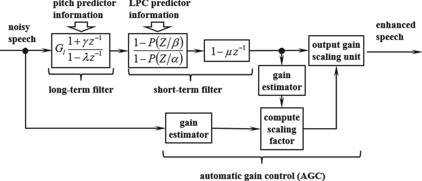
Fig. 4. Block diagram of the post-filters used in ACELP.
In G723.1, which is the International Telecommunication Union Telecommunication Standardization Sector (ITU-T) standard for Voice over Internet Protocol (VoIP) using ACELP, the pitch-emphasis technology is applied [7]. In ACELP, the speech generation process is modeled by the combination of the coefficient of the linear prediction filter that is equivalent to vocal tract and the excitation signal of the filter that is equivalent to the vocal chord sound. With this technology, the SNR of the pitch, which is the periodic component, is improved by applying the gain according to the delay that becomes the maximum correlation of the excitation signal. This improves the quality of the decoded voice.
D) Voice enhancement technology to surrounding noises
Today, mobile terminals are used in various places, such as station platforms and shopping centers, but it may become difficult to hear the received voice due to the surrounding noise. In the past, a mobile-terminal user had to manually adjust the volume of the reproduced sound to make the received voice easy to hear.
To solve this problem, technology that makes the received voice easy to hear by automatically emphasizing the received voice according to the surrounding noise (Fig. 5) has been developed and now used in the cellular phones and smartphones.

Fig. 5. Outline of voice enhancement technology.
1) Requirements of voice enhancement technology to apply to mobile terminals
Three requirements when voice enhancement technology is applied to mobile terminals are as follows.
The first requirement is achieving listenability of the received voice in a noisy environment with noise at various volumes. Because we usually use mobile terminals indoors and outdoors, there are more types of noise generated in the environment around the user than when using a landline phone. Therefore, the volume of the enhanced voice, the amplified received voice, is sometimes lower than the surrounding noise according to the usage environment in which the mobile terminal is being used, making it difficult to hear. On the other hand, when the volume of the enhanced voice is too high, the listener's auditory system will become overly stimulated, which would feel unpleasant to the receiver and become difficult to hear. Therefore, appropriate volume control of the enhanced voice according to the usage environment in which the mobile terminal is being used is necessary.
The second requirement is maintaining the naturalness of speech. Because the speech frequency might be high depending on the caller, the speech can be easily jarred when its high-frequency bands are over amplified according to the noise. Therefore, maintaining the naturalness of the enhanced voice according to various call partners’ speech qualities is necessary.
The third requirement is to improve the listenability of the speech independent of the type of the noise. Bubble noise includes the hubbub of a crowd, and the noise source is people (human voice). Therefore, bubble noise and the received voice may not be easily distinguishable with regard to audibility because the characteristics of the strength of each frequency and time variance seem like the received voice (call partner's voice). Therefore, when the surrounding noise is bubble noise, it becomes difficult to hear the received voice. Therefore, gain control according to the type of noise is necessary.
2) Features of developed voice enhancement technology
Fig. 6 shows the composition of our developed voice enhancement technology. This technology improves listenability by applying the gain to the received voice in the frequency domain according to the power of each frequency of the received voice (speech spectrum), and that of the surrounding noise obtained using the microphone in the mouthpiece of the mobile terminal (noise spectrum).

Fig. 6. Block diagram of developed voice enhancement technology.
This technology has three features, to (i) improve the listenability of the received voice for noise of various volumes, (ii) maintain the naturalness of the voice for different qualities of speech of a caller, and (iii) make the received voice easy to hear according to the type of noise (bubble noise).
We explain these features in more detail below.
(i) Gain adaptive control based on volume ratio of surrounding noise and received voice. It is necessary to increase the volume of the enhanced voice compared with the volume and constancy of the surrounding noise to make the enhanced voice easy to hear. Then, the listenability of the received voice with respect to the surrounding noise of various volumes is achieved by analyzing the power of each frequency of the surrounding noise and received voice and controlling the gain of each frequency adaptively so that the SNRs of the surrounding noise and enhanced received voice may become higher than the prescribed value.
(ii) Gain control between bands that maintain naturalness of received voice. It was revealed that the enhanced voice is harsh and its naturalness degrades when the power of the voice at high frequencies (2–4 kHz) is much larger than that of the voice at low frequencies (0–2 kHz). Though the voice quality of the caller (power of the voice at high frequencies) varies, the naturalness of the enhanced voice can be maintained by adjusting the gain in each frequency so that the differences between the power at high frequencies and that at low frequencies are within the prescribed range.
(iii) High-frequency gain control according to the type of noise. The power of the human voice is large in a pitch frequency that originates in the vibration of the vocal chords. In the overtone frequencies that are multiples of the pitch, the frequency of vocal chords changes with time. Therefore, the pitch and overtone frequencies of the human voice change with time. Therefore, bubble noise has a feature in which the time variance of the strength of the frequency component is large. Therefore, it becomes easy to hear the received voice over a variety of noise characteristics by detecting the presence of bubble noise based on the time variance of the frequency component of the surrounding noise and amplifying the received voice at high frequencies (2.0–3.5 kHz) that is a band with aural high sensitivity when a surrounding noise is bubble noise (Fig. 7).

Fig. 7. Principle of high-frequency gain control according to the type of noise.
3) Evaluation test
To evaluate the performance of the developed voice enhancement technology in terms of improving voice quality, we conducted a relative evaluation test concerning listenability. In this test, the received voice that was unamplified (original voice) and voice enhanced using the developed technology was compared in a noise environment. The test used the comparison category standard method, which is generally used as a speech quality measure method for VoIP [Reference Floriano, Mauro, Peppino and Salvadore8]. The voices were based on a five-point scale (−2: difficult to hear compared with the original voice, −1: slightly difficult to hear compared with the original voice, 0: listenability is equal to the original voice, +1: slightly easy to hear compared with the original voice, +2: easy to hear compared with the original voice). Forty-eight people ranging from twenties to eighties participated.
Fig. 8 shows the evaluation results. The listenability from the developed technology exceeded that (0) of the original voice for the participants under all noise conditions, and there was a significant difference in the listenability of the original voice. Therefore, the developed voice enhancement technology improved the listenability of the voice without depending on the noisy environment.

Fig. 8. Evaluation test results (developed voice enhancement technology).
III. SPEECH RATE CONVERSION TECHNOLOGIES
A) Background in speech rate conversion technologies
As the use of digital recorders, such as integrated circuit recorders spreads, the opportunities to record and playback voice with high sound quality has increased. The use of digital signal processor can process digital signals in real time is also spreading. As a result, the need to convert voice at different speeds and play it back with its naturalness maintained, has increased. For example, the technologies that slow the speech rate of an input voice have been developed and are used in broadcasting such as television or radio [Reference Nakamura, Seiyama, Imai, Takagi and Miyasaka9–Reference Nejime, Aritsuka, Imamura, Ifukube and Matsushima11].
Interactive speech communication in which various users talk over the telephone with each other has recently increased due to the spread of mobile terminals. Callers include those who talk fast since it is likely to talk fast in busy situations while moving etc. In such cases, the user, who is the listener, occasionally finds it difficult to hear. This is a serious problem for middle-aged people and seniors. Therefore, a speech rate conversion technology for slowing the speech rate of callers without decreasing voice quality has been developed and is used in cellular phones and smartphones.
We now give a general overview of the basic speech rate conversion technologies for mobile terminals and explain their characteristics.
B) Trends of speech rate conversion technology
Human voice includes a periodic element that originates in the vibration of the vocal chords. The pitch of the voice lowers because the cycle length changes if the speech waveform is simply enlarged in the time domain. Therefore, it is necessary to repeat the waveform with the periodic component in the voice section to maintain the voice quality of a caller (Fig. 9).

Fig. 9. Basic principles of speech rate conversion.
As the speech rate conversion technology extends speech waveform in time domain, Synchronized OverLap Add (SOLA) method was proposed [Reference Roucos and Wilgus12]. This method searches the connecting location between frames made to overlap by not expressly detecting the periodic pattern and uses the standard based on the cross-correlation. In addition, Pitch Synchronized OverLap Add method was proposed [Reference Moulines and Charpentier13]. This method extends the voice section by detecting the pitch period from the input voice and pasting the pitch periodic components.
In these methods, by cutting out and overlapping the frame of the input speech, and adjusting the range of repetition for the connection, the speech rate can be changed with the tone of the speech kept (Fig. 10). On the other hand, the speech quality deterioration was occasionally caused when applying to the transition section where the pitch period was indistinct.
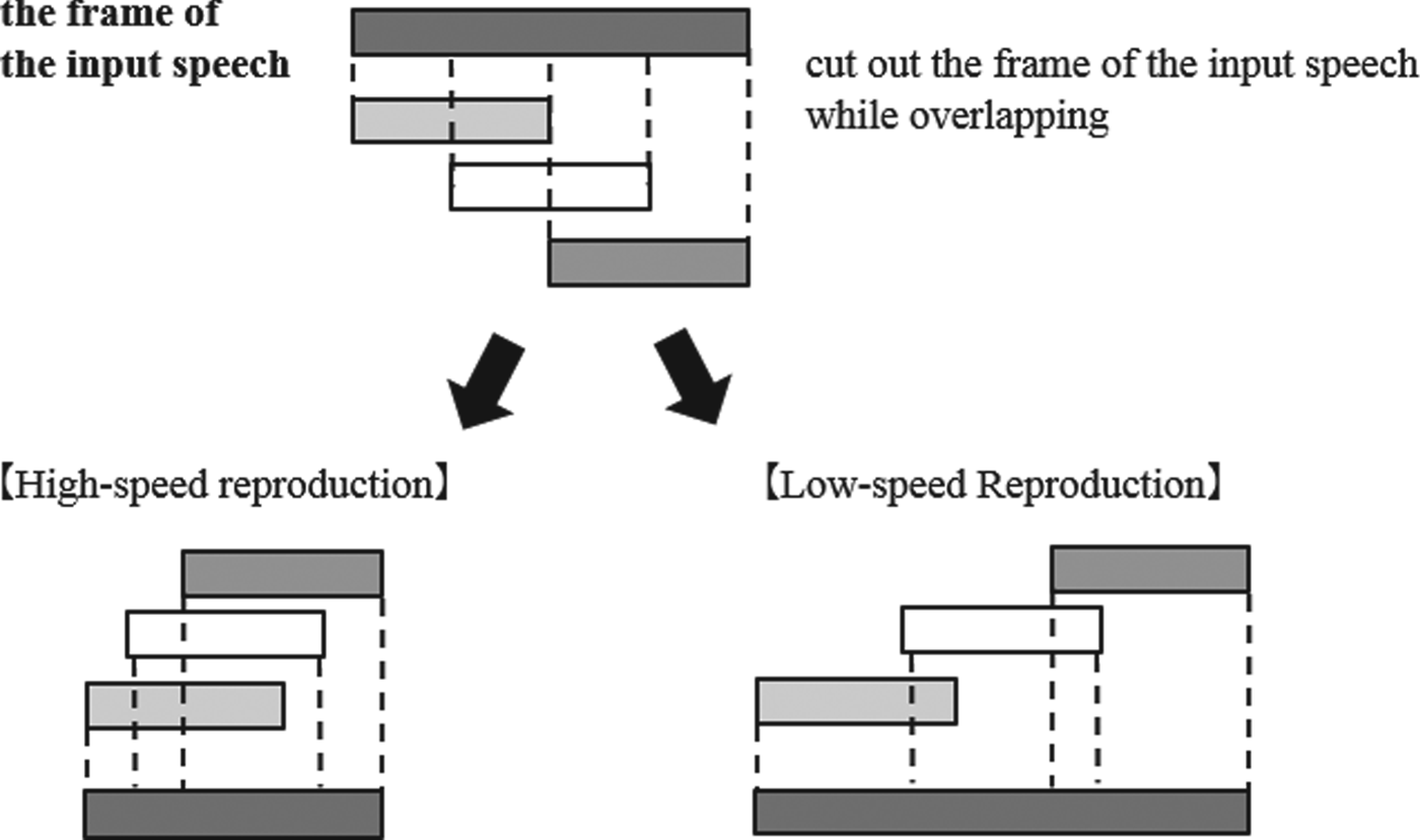
Fig. 10. Principles of OverLap-Add method.
To solve this problem, Phase Vocoder was proposed [Reference Laroche and Dolson14]. With this technology, the periodic component is extracted by converting the voice into a frequency domain and calculating the phase of each frequency component.
C) Requirements of speech rate conversion technology to apply to mobile terminals
The following requirements occur when the basic speech rate conversion technology is applied to mobile terminals.
The first requirement is slowing the speech rate of the received voice while maintaining voice quality. The amplitude and the pitch period of natural speech waveform change with time. However, if the speech waveform is simply repeated continuously to slow the received voice, a mechanical allophone is generated because the changes at the amplitude and pitch period locally decrease, decreasing the converted voice quality. Therefore, it is necessary to slow the speech rate of the received voice while maintaining voice quality.
The second requirement is preventing the call partner from feeling uncomfortable in the conversation even if the user slows his/her speech rate. Because the reproduction time of the sent voice becomes longer than the received voice by slowing the speech rate, the time the call partner finally hears the voice is delayed. As a result, the conversation drags on and it becomes difficult to communicate in real time. Therefore, the call partner may feel uncomfortable when the gap of the conversation is too long.
D) Features of developed speech rate conversion technology
Fig. 11 shows a block diagram of the developed speech rate conversion technology. It detects the voice section and silent section (where the voice is not included) included in the received voice, and the speech rate of the received voice is slowed by shortening the silent section while extending the voice section.

Fig. 11. Block diagram of developed speech rate conversion technology.
The developed technology has two features, (1) extending the voice without changing voice quality and (2) preventing the call partner from feeling uncomfortable in the conversation even if the user slows his/her speech rate.
1) Voice extension that does not change voice quality of call partner
With the above-mentioned SOLA method, the speech rate of a voice is converted slowly by extracting the section where the correlation is high (the periodicity is high) using autocorrelation analysis and repeating the speech waveform in the extracted section. In addition, by controlling so that the frequency of the repetition each unit time may become below the predetermined threshold, the characteristic that the amplitude and the pitch period of the natural speech waveform change with time is not impaired.
Consequently, speech rate conversion that does not generate a mechanical allophone was achieved.
2) Delay control that does not lead to obstruct conversation even if speech rate is slowed
We investigated the length of delay in an interactive telephone call when the listener felt that there was an obstacle in the conversation. We assumed there is no obstacle in a conversation if the delay is shorter than one second. The developed technology shortened the silent section to reduce delay and gradually returned the speech rate to normal when the delay was one second or longer (Fig. 12). The call partner did not experience any obstacle in the conversation because the delay according to the voice extension was within one second, resulting in real-time maintenance of the interactive telephone call.

Fig. 12. Example using developed speech rate conversion technology.
The delay is reduced by shortening the waveform in the silent section while extending the waveform in the voice section. If the delay is over one second, the waveform in the voice section is not extended (returns to original speech rate).
E) Evaluation test
To evaluate the effectiveness of the developed speech rate conversion technology in term of improving voice quality, we conducted a relative evaluation test concerning listenability. The processing sound that slowed the speech rate using the developed technology and the received voice of original speech rate (original voice) were compared.
The evaluation was measured based on a seven-point scale (−3: very difficult to hear compared with an original voice, −2: difficult to hear compared with the original voice, −1: slightly difficult to hear compared with the original voice, 0: listenability equal to the original voice, +1: slightly easy to hear compared with the original voice, +2: easy to hear compared with the original voice, and +3: very easy to hear compared with the original voice). Twenty-eight people ranging in age from thirties to eighties participated. The speech rate of the original voice was 150–200 words per minute, which is considered fast for middle-aged people and seniors.
Fig. 13 shows the evaluation results. The listenability with the developed technology exceeded listenability (0) of an original voice for the participants in all age groups, and there was a significant difference in the listenability of the original voice. Therefore, the developed speech rate conversion technology improved listenability no matter the age of the listener when the speech rate of the received voice was fast.

Fig. 13. Evaluation test results (developed speech rate conversion technology).
IV. IMPLEMENTATION OF ALGORITHMS OF DEVELOPED TECHNOLOGIES ON MOBILE TERMINALS
We now discuss implementation measures to promote our developed technologies to provide high performance in real environments such as streets, platforms, and offices.
A) Attaining high performance of developed technologies at various speech qualities
The received voice quality depends on the speech quality of the call partner, acoustic characteristics of mobile terminal, and transmission path (Fig. 14). Without speech control, our developed technologies will not perform successfully and speech quality will vary according to the conditions. (Fig. 15a). We have developed a received-voice-quality-control technology. With this technology, we can adjust the received voice quality and achieve the desired performance of our voice enhancement and the speech rate conversion technologies (Fig. 15b).

Fig. 14. Factors of received speech quality.

Fig. 15. Attaining “standard speech quality” with adaptive speech quality control. (a) Without adaptive speech control (upper). (b) With adaptive speech quality control (lower).
Fig. 16 shows a diagram of this technology. It first analyzes the received voice frequency characteristics then calculates corrected gains to match reference values. By applying these corrected gains to the received voice, preferable speech quality will be attained. For example, when the power of lower frequencies is larger than that of higher frequencies, muffled speech will result. We define preferable speech quality for mobile terminals as “standard speech quality”. It is a “rich, deep resonant tone”. With this technology, we adjust the frequency component to implement “standard speech quality” for cellular phones.

Fig. 16. Diagram of speech quality control.
B) Attaining high performance of developed technologies in noisy environment
Cellar phones have to provide good performance under various environments, from noisy streets and restaurants to quiet rooms. In noisy environments, speech cannot be heard over the noise (SNR degradation). In this condition, speech quality becomes increasingly difficult to maintain. Our speech rate conversion technology slows the voice in order to easier listening. To recover from the delay, this technology detects and deletes silence between speeches. Therefore, voice activity detection (VAD) affects the performance of the technology.
VAD detects voice that has different characteristics than environmental noise. It uses SNR as one of the characteristics. It adaptively controls the threshold to detect voice depending on the strength of the environmental noise and calculates the sound characteristics for VAD using high SNR frequency components. We expect that high SNR frequency components will be less affected by environmental noise than low SNR frequency components. This will enable VAD to provide high performance under noisy environments (Fig. 17). VAD detects more than 60% silence duration under noisy environments, improving the effectiveness of our speech rate conversion technology.

Fig. 17. VAD mechanism.
V. OTHER VOICE-QUALITY-IMPROVEMENT TECHNOLOGIES
In addition to above-mentioned voice enhancement technology and the speech rate conversion technology, a voice enhancement technology based on user movement that makes the received voice easy to hear according to the user's movement and a voice-enhancement technology based on user age that improves hearing according to the age of the user have been developed.
A) Voice enhancement technology based on user movement
When we are moving, commuting, going to school, and shopping, it is likely we talk on our mobile terminals while walking or running. In such a situation, it might become difficult to hear the received voice because the ear piece of the mobile terminal tends to leave from the user's lughole by the user's head and arm moving along with walking. Therefore, a technology for amplifying the strength of each frequency of the received voice according to the user's movement (walking/running) has been developed. This technology detects the degree of shake (movement) using the motion sensor installed in mobile terminals and determines whether the user is walking or running. Listenability improves by amplifying the strength of each frequency of the received voice according to the determined movement.
B) Voice enhancement technology based on user age
It is generally known that hearing becomes difficult as a person ages and the ability to hear voices decreases (Fig. 18). Therefore, a technology that improves listenability by amplifying the received voice according to the user's hearing ability has been developed.

Fig. 18. Hearing ability decreases with increasing age.
The features of development technology will be described below.
1) Speech quality correction based on user age
By using the correlation between hearing ability and the age, listenability of seniors has been improved by assuming the hearing-loss level from the age the user inputs beforehand and amplifying the received voice based on that hearing-loss level.
2) Amplification amount control according to input volume
For seniors, it is difficult to hear faint sounds, but loud noises can be heard. Therefore, simply amplifying all sounds would be annoying to seniors. Therefore, when the input volume (volume of the received voice) is low, the input voice is amplified based on the hearing loss level, as shown in Fig. 19. When the input volume is high, the input voice is amplified to not exceed the volume at which unpleasantness is experienced. Through this control, such unpleasantness is eliminated.

Fig. 19. Amplification amount control according to input volume. Sound pressure level (SPL).
VI. CONCLUSION
We described the features of voice enhancement and speech rate conversion technologies for improving the listenability of the received voice in mobile terminals, implementation of the algorithms of the developed technologies on mobile terminals.
Because the developed technologies can support conversations, the basic element in interpersonal communication, we are hopeful that they will be applied not only to mobile terminals but also in fields such as broadcasting, communications, education, and over-the-counter customer service. In addition, the aging population is increasing not only in Japan but also in another country around the world. Therefore, technologies that support communication are increasingly necessary.
Cellular phones and smartphones designs have recently become diversified. Therefore, it is necessary to adapt to a variety of speech quality conditions. We intend to continue to increase the ease in hearing and speaking and improve communication quality.
ACKNOWLEDGEMENT
We thank the reviewers for comments that greatly improved the manuscript. We also appreciate the advices and materials given by other researchers of Media Processing Laboratory in Fujitsu Laboratories.
Taro Togawa received his M.S. degree from Tokyo Institute of Technology in 2004, and joined Fujitsu Laboratories Limited. His main research interests are speech and audio signal processing methods. He was awarded “The Commendation for Science and Technology by the Minister of Education, Culture, Sports, Science and Technology (MEXT)” in 2012.
Takeshi Otani received his M.S. degree from Hokkaido University in 2000, and joined Fujitsu Laboratories Limited. His main research interests are speech signal processing methods, technologies for implementation, and development of application. He was awarded “The Commendation for Science and Technology by the Minister of Education, Culture, Sports, Science and Technology (MEXT)” in 2012.
Kaori Suzuki received her M.S. degree from Hokkaido University in 1986, and joined Fujitsu Limited. She has researched and developed the listenability improvement technologies for the mobile terminal. She was awarded “The Commendation for Science and Technology by the Minister of Education, Culture, Sports, Science and Technology (MEXT)” in 2012.
Tomohiko Taniguchi received his B.S. degree from the University of Tokyo in 1982, and joined Fujitsu Laboratories (Ph.D. from the University of Tokyo, 2006). He was a visiting scholar at Stanford University (1987–1988), and was with Fujitsu Laboratories of America, Sunnyvale, CA, USA (1996–2000). Currently he is with Fujitsu Laboratories Limited, Kawasaki, Japan, as a Research Principal. He has been active in the field of signal processing for more than 30 years, served for international conferences/committees (13 times Symposium Chair in IEEE ICC/Globecom), and is recognized for his inventions (essential patents for international standards, such as ITU-T, MPEG, and 3GPP). He is a recipient of numerous awards for his papers, patents, and contributions to the academic society. Currently he gives lectures at Beijing University of Posts and Telecommunications (as distinguished Visiting Professor since 2013), and at DuyTan University (as Guest Professor since 2014). He is a Fellow of IEEE and IEICE.


