


Introduction
Satellite images provide valuable information on glaciated areas which are scarcely explored by man and where observations are difficult owing to the complicated environment (Reference Hall and MartinecHall and Martinec, 1985). At present, the Chinese Glacier Inventory has used some results of satellite interpretation (Reference Yafeng, Zongtai and ChaohaiShi and others, 1982) and has accelerated its working course. But since the grey level signature of snow-ice spectrum is narrow, only glacier boundary, area and types, and the snowline location can be identified by using a single channel image or standard false colour composite. These snow-ice categories on the glacier surface are difficult to interpret.
In order to interpret the surface features effectively, it is necessary to use image processing. Computer digital image processing has been extensively developed recently, since it can conveniently operate existing remote sensing software systems to extract desired information from digital images. In this paper, the nonlinear enhancement on image transparencies for improving interpretation is presented by means of duplicating processing. Though its capability to extract information is limited, its operation is simple and may be useful when there are no computer processing facilities.
Principle and Method of Nonlinear Colour Enhancement
In principle, the film density of photogrammetric and scanning images in the visible and infrared bands can be regarded as records of reflected or emitted spectral radiation energy from objects on the Earth's surface. The presentation of each object on the image is based on the difference of density or transmittance among them, so the difference of reflected radiation energy among snow-ice and others can make the transmittance of each part on film appear as corresponding changes; these changes become signatures to distinguish objects.
The ratio of transmittance among objects on a Multi-Spectral Scanner (MSS) or Thematic Mapper (TM) channel positive film transparency corresponds to the ratio of exposure acquired by sensors among corresponding objects (Reference Lillesand and KieferLillesand and Kieffer, 1979). It can be expressed as follows:

where T 1 and T 2 are positive film transmittanccs of objects 1 and 2 in a channel; E 1 and E 2 are exposures of objects 1 and 2 acquired by sensors; W 1 and W 2 are reflected or emitted radiant intensities from objects 1 and 2; γ is the contrast coefficient of the film. E1/E2 equals W 1/W 2 for the same remote sensing conditions, so Equation (1) could be set up and various objects interpreted by using transmittance or density on film. If γ equals 1, the topography seen from space will be shown on corresponding channel positive film. This is referred to as linear restoration. If γ is greater than 1, the difference among transmittance of the objects will be exaggerated according to a nonlinear logarithmic relationship. Therefore, the colour difference among objects on the composite may be increased, and this is referred to as nonlinear colour enhancement.
Since the reflectivity differences are small among various snow-ice objects in each MSS channel, there is little luminance difference in false colour composite and this makes distinction difficult. In addition, the MSS or TM films used possess density compression at both ends of the grey scale. Therefore the Landsat scales are distorted and difficult to analyze by image processing techniques. In this paper, the nonlinear colour enhancement of images is used to solve this problem partially. In our test, the film density having defined snow-ice types in previous field exploration was digitized and transformed to a range of 0-255 digital number F by using Multi-Colour Data System model NAC-4200F (NAC Inc., 1984). First of all, the mean, F, and the amplitude of each snow-ice type in four channels are analyzed to obtain the optimum channel image and their association to particular surface characteristics.
According to the theory of digitizer and statistical analysis (Reference SlaterSlater, 1980), NAC-4200F measures the film density D to 0-255 F as follows:
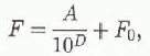
where A is the transformation coefficient dependent on illumination condition, and F 0 is the noise term influenced by environmental conditions of NAC-4200F, such as environmental temperature. By controlling the input condition through aperture, one can get an ideal digital image on NAC-4200F screen. Figure 1 shows the statistical mean F and its triple standard deviation range for five categories of snow-ice objects on a Landsat-2 image from the Qpmolangma Peak region acquired on 20 December 1976. Each sample was repeated eight to 12 times. It is seen from Figure 1 that: (1) the snow and bare ice are overlapping in MSS-4, -5 and -6 and can be distinguished in MSS-7 only; (2) the bare ice and ice pinnacles can be distinguished in MSS-6 and -7; (3) the moraine-covered ice surface and ice pinnacle are hardly distinguishable in a single channel image, but they may be distinguished in false colour composites by colour differences; (4) a moraine-covered gully bed and ice surface also have a colour difference in composite, because their F magnitude inverts in MSS-4 and -5. It is evident from Figure 1 that using MSS-6 instead of MSS-5 to compose a false colour composite will provide more information on the glacier surface than that in standard false colour composite. The MSS or TM images generally provided come through duplication processes several times, so γ in Equation (1) is a product of all γ from previously duplicated films. The relationships between the film density D and the grey scale steps of the above-mentioned Landsat-2 MSS-4, -5, -6 and -7 images are measured with a densimeter. Through corresponding calculations on this measurement, the values of 1.47, 1.39, 1.21 and 1.31 are found for respective channels. This weak nonlinear effect can be duplicated on high contrast films to expand the colour difference among objects in a composite. Since the tolerance of conventional films is narrow, the image resolution could decrease to lose some information when high contrast film is duplicated. Therefore, it is necessary to select the duplication times and channel film to satisfy the interpretation content of studied features.

Fig. 1. F mean measuredfrom negative film density of ice, snow and moraine on MSS-4, -5, -6 and -7 images and their triple standard deviation (represented by longitudinal segments around points of F mean).
Effect and Evaluation of Nonlinear Enhancement Processing on Images
The existing negative films are regarded as original negative one “Negative I” in our test. The γ = 2 high contrast films are used to print positive films “Positive I” and once more to duplicate negative films “Negative II”. Therefore, there are three groups of MSS-4, -5, -6 and -7 images of different contrast coefficients. Figure 2 shows the relationship between film density and grey scale steps on MSS-6 images of these three duplicated groups. Then the negative films are inverted to positive to make directly a composite frame of false colour image on the NAC-4200F screen together with images of other channels for observing the processing effects. Figure 3 shows the F values for five objects on both “Positive I” and “Negative I” image groups. It can be seen that the lvalues among the five objects in “Positive I” have larger differences than on original “Negative I”. For example, the F mean difference between snow and bare ice on “Negative I” MSS-7 is 3, but 17 on “Positive I”. Although the standard deviation of F is slightly larger, the difference between the mean values is clearly increased.

Fig. 2. Relationship between film density and grey scale steps on MSS-6 image of three duplicated groups.

Fig. 3. Relationship between MSS channel and F mean measured from images of “Negative I” and duplicated “Positive I”. The legends are the same as in Figure 1. (“Negative I” F has already turned over to positive film F.)
Based on qualitative analysis of three duplicated groups, several combinations of false colour composite have been prepared. Since “Negative II” has lost a lot of information already and individual “Positive I” only can obviously change several narrow grey scale range, it is necessary to select individually suitable “Negative I” into combination in our test. Table 1 lists a combination of duplicated images to make up a false colour composite of the Qpmolangma region by y ≅ 1 MSS-4 and y ≅ 2 MSS-6 and -7 images. When a comparison of a false colour composite is made with a standard colour composite, the difference between snow (white), bare ice and ice pinnacle (yellow), moraine-covered ice surface (brown moraine under yellow background of ice surface) and moraine-covered gully bed (light greyish white) can be distinguished more clearly in the false colour composite. The yellow background of the ice surface becomes gradually lighter from the upper to the lower reach of the glacier tongue, and the brown moraine cover becomes darker. This indicates that the moraine-covered layer becomes thicker. Other features, such as bare ice, ice pinnacles and hilltops, were revealed more clearly in a false colour composite than in a standard one. All these new findings were confirmed by air surveys.
Table 1. One of the combinations to make up a false colour composite

Because snow reflectivity on a glacier surface is generally very high, making MSS images saturated, the distinction between snow categories using a false colour composite cannot be improved by nonlinear enhance-ment. In addition, the lower resolution makes the interpretation of some glacier features difficult. For example, several middle moraines are mixed together and cannot be divided; the outline of the glacier boundary is coarse and causes larger errors in measuring location change. Thus, it is best to use photographs prepared by both methods to achieve the best interpretation.


