


Introduction
Since titanium dioxide (TiO2) nanoparticles first has been combined with dye molecules to fabricate low-cost photovoltaic device in 1991, dye-sensitized solar cells (DSCs) have attracted extensive interest in the past few decades as a promising candidate to convert solar energy to electricity.[ Reference Oregan and Gratzel 1 – Reference Wang, Zakeeruddin, Moser, Nazeeruddin, Sekiguchi and Gratzel 3 ] Although using TiO2 nanoparticle films with collaborated silyl-anchor and carboxy-anchor dyes has achieved a power conversion efficiency of higher than 14% in 2015,[ Reference Kakiage, Aoyama, Yano, Oya, Fujisawab and Hanaya 4 ] TiO2 as photoanodes in DSCs still face many challenges.[ Reference Hendry, Koeberg, O'Regan and Bonn 5 , Reference Zhu, Neale, Miedaner and Frank 6 ] It has become a focus recently that looking for alternative metal oxide semiconductors with wide band gap and good photoelectrochemical properties.[ Reference Chen, Huang, Cheng and Caruso 7 – Reference Tian and Cao 10 ] ZnO nanostructures for DSC applications has shown that they can offer large specific surface areas with well-controlled morphologies, direct electron pathways with much higher electron mobility, and also can reduce the combination rate when the surface defects are properly controlled.[ Reference Zhang, Dandeneau, Zhou and Cao 11 – Reference Fei, Tian, Wang, Liu, Lv, Zhao and Cao 13 ] Tin oxide (SnO2) as a promising alternative semiconductor has many advantages for DSCs: (1) good electron mobility, indicating electron transport fast in photoanodes and (2) large band gap (3.6 eV) and more-negative conduction band minimum, which can enhance the light harvesting in the near-infrared spectral region when combined with small band gap sensitizer.[ Reference Wang, Tian, Fei, Lv, Liu, Zhao and Cao 14 ]
Many different nanostructures of SnO2 have been synthesized with a variety of methods with emphasis to avoid its weakness, such as electron recombination and surface defects.[ Reference Green, Palomares, Haque, Kroon and Durrant 15 ] Low-dimensional nanostructures of SnO2 have been widely reported, including zero-dimensional (0D) nanoparticles,[ Reference Xu, Zhuang and Wang 16 ] one-dimensional (1D) nanorods,[ Reference Zhang, Sun, Yin and Yan 17 ] nanobelts,[ Reference Pan, Dai and Wang 18 ] nanotube,[ Reference Zhang, Li, Yang, Que and Liu 19 ] and nanowires (NWs).[ Reference Wang, Jiang and Xia 20 ] The process of SnO2 nanostructure synthesis is always related to chemical reaction of tin precursor and crystallization of SnO2. Different reaction parameters, such as the concentration of precursor solution, pH value and addition agent, will influence the morphology of SnO2 nanostructure eventually. In addition, in order to solve the problem that less dye adsorption of SnO2 owing to lower isoelectric point (i.e.p., at pH 4–5), coating other metal oxide such as TiO2 (i.e.p., at pH 6–7)[ Reference Kay and Gratzel 21 ] can increase the cell efficiency of DSCs.[ Reference Ito, Makari, Kitamura, Wada and Yanagida 22 , Reference Park, Kang, Kim, Ryu, Chang, Kim, van de Lagemaat, Benkstein and Frank 23 ] For example, in 2011 Wu et al.[ Reference Wu, Chen, Lou and Hng 24 ] synthesized hierarchical structure consisting of 2D SnO2 nanosheets and other metal oxides to increase the open-circuit photovoltage. Among the large number of materials, 1D TiO2 NWs with superior light-scatting ability can provide a direct way to transport electrons and enhance the performance of the whole solar cells.[ Reference Law, Greene, Johnson, Saykally and Yang 25 – Reference Zhao, Yu, Fan, Zhai and Wang 29 ] In addition, TiO2 NWs can also provide a rapid electron transfer and reduce the electron recombination rate. As a result, the power conversion efficiency is greatly improved.[ Reference Yin, Que, Fei, Xie and He 30 ]
In this paper, SnO2 hollow spheres (HSs) made of SnO2 nanoparticles modified with TiO2 NWs were employed as photoanodes for DSCs. The uniform SnO2 spheres are synthesized without using any template through a hydrothermal method, which makes the reaction product with better crystallinity and less surface defects. When such SnO2 HSs were modified with TiO2 NWs, the large specific surface area, less surface defect, and good light-scatting properties make it an attractive alternative photoanode materials with high dye loading, effective light absorption, direct electron transport path, and reduced charge recombination. The short-circuit photocurrent density and open-circuit photovoltage both have been greatly increased. The power conversion efficiency of the solar cell based on SnO2 HSs coated with 3D TiO2 NWs as photoanodes reached 2.9%, which presents six times of enhancement as compared with the DSCs with SnO2 HS anodes.
Experimental methods
Synthesis of SnO2 HSs
The 10 mmol of SnCl2 (1 M in concentration) were dissolved in 10 mL mixture of ethanol and hydrochloric acid (9:1 in volume) and stirred for 5 min. The solution was transferred to a 35 mL reaction tube and reactor cavity of the CEM Discover microwave system. The synthesis parameters were set as: T = 180 °C, dwell time = 2 h, power = 120 w, and pressure = 17 bars. After cooling naturally, the precipitate was harvested by centrifugation at 8000 rpm for 30 min and washed thoroughly with deionized (DI) water for at least three times. The brown powder was calcined at 450 °C for 3 h to remove the inner carbon sphere completely to obtain SnO2 HSs.
Preparation of SnO2 paste
SnO2 powders (0.18 g) were placed in an agate mortar, and 5.0 mL of ethanol was added dropwise into the mortar. The SnO2 powders were ground for 30 min. The ground SnO2 was then transferred to a solution of terpineol (0.73 g) and ethyl cellulose (0.09 g) in a 10 mL beaker under magnetic stirring. The dispersion was homogenized by means of ultrasonic and magnetic stirring overnight. A layer of SnO2 film was prepared by the doctor blade technique. The film was sintered at 500 °C for 60 min in air to remove any organic compounds.
Synthesis of SnO2 HSs coated with TiO2 NWs
K2TiO(C2O4)2 (0.35 g) was added to the mixture solvent containing diethylene glycol (DEG) and DI water in different volume ratios (0:20, 1:19, 10:10, 19:1), while the total volume of the solution was 20 mL. The solution was transferred to a 50 mL Teflon-lined stainless steel autoclave. Then as-prepared SnO2 films were placed at an angle against the wall of the Teflon-liner with the film side facing down. The hydrothermal synthesis was carried out by putting the autoclave in an oven at 180 °C for 6 h with a heating rate of 5 °C/min and air-cooled to room temperature naturally. Subsequently, the samples were rinsed with DI water, ethanol, and sintered at 500 °C for 60 min in air to increase crystallinity.
Fabrication of DSCs
The electrodes with a cell area of 0.25 cm2 were immersed in a 0.25 mM N719 sensitizer dye for 18 h. The counter-electrodes were Pt-coated fluorine doped tin oxide (FTO), and the electrolyte was contained I −/I 3− redox. The DSCs with TiO2 NWs treatment (DEG: DI = 1:19) and without TiO2 NWs treatment were designed by SnO2 HS–TiO2 NW and SnO2 HS.
Characterization
X-ray diffraction (XRD) measurements were conducted on an X'Pert PROS (Philips Co.) with a radiation of Cu K α (λ = 1.54060 Å). Hitachi SU8020 scanning electron microscope (SEM) system was employed to analyze the morphology. The absorption spectra were measured using a Shimadzu UV-3600 spectrophotometer. N2 adsorption–desorption isotherms were recorded on ASAP2020 instrument (Micromeritics Co.), and the specific surface areas [Brunauer-Emmett-Teller (BER)] were calculated using the BET equation. Desorption isotherm was used to determine the pore-size distribution using the Barret–Joyner–Halender (BJH) method. The photovoltaic characteristics of the solar cells were evaluated using simulated AM 1.5 sunlight with an output power of 100 mW/cm2. The incident monochromatic photon-to-electron conversion efficiency (IPCE) plotted as a function of excitation wavelength were recorded IM6ex (Zahner, Germany) using light-emitting diodes (LED; λ = 455 nm) driven by Expot (Zahner, Germany). The electrochemical impedance spectroscopy (EIS) data were fit to the equivalent circuits by using Zview software (Scribner Associates). Impedance measurements were carried out under illumination from LED.
Results and discussion
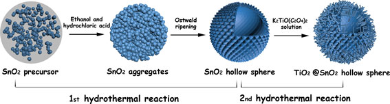
Scheme 1 is the proposed schematic illustrating the formation process of the SnO2 HSs and subsequent modification with TiO2 NWs. The formation of SnO2 HSs without using templates could be ascribed to a simple Ostwald ripening process as reported in literature.[ Reference Wang, Li, Gao, Tang, Feng, Li and Guo 31 ] The solid spherical aggregates were first formed by the self-assembly of SnO2 nuclei through the oxidation and hydrolysis reactions of Sn2+. Since the particles that located in the inner cores have poor crystallinity as well as higher surface energies, they are more easily dissolved at high temperatures (fast kinetics in hydrothermal growth condition). With reaction proceeds, the interior cavities will be generated within the solid spheres, and hollow SnO2 spheres can be obtained. Besides, the as-prepared thorn-like nanoparticles around the HSs probably can be explained by the acid etching effect of hydrochloric acid. The uniformly sized SnO2 HSs of approximately 200 nm in diameter are composed of 15 nm nanoparticles, then blade coating on the FTO. The SnO2 films are coated with TiO2 NWs using the hydrothermal synthesis in the Teflon-liner stainless steel autoclave. In order to fabricate TiO2 NWs, the SnO2 films immersed in a solution with titanium potassium oxalate and a mixture solvent containing DEG and DI water. In reaction process, DEG plays a role as capping agent to control morphology of TiO2 nanostructure by means of changing volume ratios of DEG and DI water.[ Reference Wu, Xu, Rao, Feng, Su and Kuang 32 , Reference Wu, Lei, Rao, Xu, Wang, Su and Kuang 33 ] The advantage of this hierarchical nanostructure lies in HSs provided with the large specific surface area and enhanced light scatting, at the same time TiO2 NWs can provide a direct transport path for electrons transport. In addition, the surface of SnO2 HS is also passivated by TiO2 to reduce the surface defects.
To clearly show the composition changes in the materials, we measured the SnO2 HSs, and SnO2 HSs modified with TiO2 samples with an x-ray diffractomer. As shown in Fig. 1, the XRD patterns of SnO2 HS and SnO2 HS–TiO2 NW have undergone significant changes. SnO2 HS powder has the tetragonal rutile structure with lattice constants of a = 4.738 and c = 3.187 Å, while SnO2 HS–TiO2 NW powder has the TiO2 anatase structure with lattice constants of a = 4.593 and c = 2.959 Å. No other impurity crystal is detectable, which suggests that template-free growth can effectively form high-purity tetragonal rutile SnO2 crystal and the subsequent hydrothermal growth results in the growth of anatase TiO2 NWs.
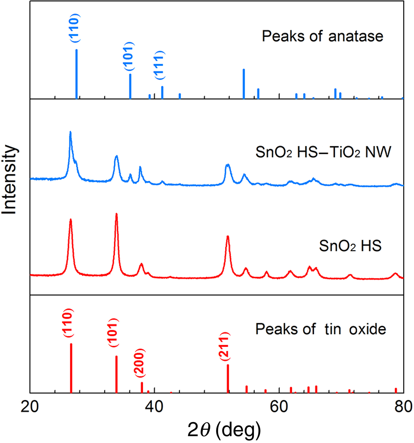
Figure 1. XRD patterns of SnO2 HS and SnO2 HS–TiO2 NW powders showing SnO2 HSs having a rutile crystal structure while TiO2 NWs with an anatase crystal structure.
Figures 2(a) and 2(c) are the different magnification SEM images of SnO2 HSs. The template-free hydrothermal method can form SnO2 HSs with almost identical appearance. A close look reveals that the SnO2 HSs of 200 nm in diameter are the assembly of nanoparticles of 15 nm in diameter. Figures 2(b) and 2(d) show the different magnification SEM images of SnO2 HS–TiO2 NW structure. When titanium potassium oxalate exists in the mixture solvent containing DEG and DI water under sufficiently high temperature and long duration, it can form a globular structure consisting of TiO2 NWs. It can also form TiO2 NWs on the surface of SnO2 HSs because of increasing active growth sites. Adjusting DEG and DI water volume ratios to 1:19, TiO2 NWs grow with a diameter of 30–50 nm.

Figure 2. SEM images of: (a, c) SnO2 HS nanostructure, (b, d) SnO2 HS with TiO2 NWs structure.
The SnO2 HS and SnO2 HS–TiO2 NW powders were further characterized by means of nitrogen sorption isotherms at 77 K as shown in Fig. 3(a), and the corresponding pore-size distribution is presented in Fig. 3(b). It is found that the SnO2 HSs have a very low BET surface area, only 20.8 m2/g with an average BJH pore diameter of 17.3 nm and a pore volume of 0.15 cm3/g. By contrast, the SnO2 HS–TiO2 NWs have 39.3 m2/g BET surface area with BJH pore diameter 10.5 nm and 0.09 cm3/g pore volume. Although it might look against the intuition, SnO2 HS sample with relatively low pore volume and low BET surface area is reasonable. The nitrogen sorption isotherms through surface adsorption and capillary condensation are valid in the microporous and mesoporous regions. When the voids inside the SnO2 HSs are larger than 100 nm, isotherms can have significant deviation. The isotherm for SnO2 HSs in Fig. 3(a) demonstrated a substantial reduction in adsorbed nitrogen volume at relative pressures ranging from 0.05 to 0.65, and suggested a possible capillary force-induced shrinkage and/or partial collapse of the porous structure. So the pore volume and possibly the BET surface area measured here with nitrogen sorption isotherms are most likely much smaller than the real values. TiO2 NWs grown on the surface of SnO2 HSs and filling the space between spheres would contribute to the increased BET surface area with reduced pore size and porosity. Figure 3(c) shows two films’ light-scatting ability measured by the UV–vis diffuse reflectance spectroscopy, and reveals that the diffuse reflection of SnO2 HS film is much higher than the SnO2 HS–TiO2 NW film. Here are three possible reasons about two films with different diffuse reflection: (1) the growth of TiO2 NWs on the surface of SnO2 HS layer would definitely increase the surface roughness, and thus reduce the light-scatting ability of the SnO2 HS–TiO2 NW film. (2) The SnO2 HS–TiO2 NW film would definitely have a lower packing density, which would contribute to a reduced diffuse reflection. (3) Although TiO2 possesses the index of refraction of 2.488, appreciably higher than that of SnO2, 2.006,[ Reference Patnaik 34 ] the amount of TiO2 might be too small to make significant impact.

Figure 3. (a) Nitrogen adsorption and desorption isotherms at 77 K, and (b) the pore-size distribution of SnO2 HS and SnO2 HS–TiO2 NW powders. (c) The diffuse reflectance curves and (d) transmission spectra of SnO2 HS and SnO2 HS–TiO2 NW photoanodes without dye loading.
BET surface area differences between the sample SnO2 HS and SnO2 HS–TiO2 NW also affect the amount of dye adsorption, and then have an impact on the performance of DSCs based on two different photoanodes. Figure 4(a) shows the curves of dye absorption and details summarized in Table I. Owing to the poor adsorption property of SnO2 HS photoanode with dye molecules, it provides very low dye loading of 2.12 × 10⁻⁸ mol/cm2. By contrast, TiO2 have a good associativity with dye molecules and the loose structure because of the NWs existing and the value of dye loading in SnO2 HS–TiO2 NW photoanode is 7.64 × 10⁻⁸ mol/cm2, more than three times of the amount of dye loaded on SnO2 HS photoanode. The ameliorative dye loading can obviously improve the light harvesting, possibly resulting in the enhanced photocurrent density and subsequently the power conversion efficiency of the solar cells if other properties are kept the same. According to the BET surface area data, SnO2 HS–TiO2 NW sample has the specific surface area, 1.8 times larger than that of SnO2 HS sample, whereas 3.6 times more dye loading than SnO2 HS. The possible explanation for such differences in BET surface areas and in dye-loading data is ascribed to the different dye-loading ability of metal oxides stemming from their different surface chemistry and surface energy, SnO2 has less dye adsorption owing to its lower isoelectric point (i.e.p., at pH 4–5), while TiO2 has higher isoelectric point (i.e.p., at pH 6–7).[ Reference Kay and Gratzel 21 ]

Figure 4. (a) The comparison of UV–vis absorption spectra of dyes dissolved in ethanol, unloaded from respective SnO2 HS and SnO2 HS–TiO2 NW photoanodes; (b) IPCE spectra of DSCs with the two photoanodes; (c) the Nyquist plots; and (d) Bode curves of electrochemical impedance spectra of SnO2 HS and SnO2 HS–TiO2 NW photoanodes with a forward bias of open-circuit voltage, the inset is an equivalent circuit of the solar cells.
To further understand the photovoltaic properties of DSCs with the photoanode of SnO2 HS and SnO2 HS–TiO2 NW, the IPCEs were characterized with the results shown in Fig. 4(b). The IPCE is defined as the number of electrons detected in the external circuit produced by an incident photon at a given wavelength, related to electron injection efficiency, dye regeneration efficiency, charge collection efficiency, and light-harvesting efficiency.[ Reference Ahn, Kim, Chi and Kim 35 ] The IPCE values of the solar cell constructed with SnO2 HS–TiO2 NW powder of about 45% are much higher than that of the device based on SnO2 HS powder, of <25%. This figure clearly showed that the solar cells based on SnO2 HS–TiO2 NW electrode has better performances, attributing to better dye loading and light scattering in the whole wavelength region from 400 to 750 nm. It is noted that two photoanodes both have HS structures, which have a good impact on light-scattering properties in longer wavelength regions.[ Reference Ahn, Kim, Chi and Kim 35 ]
The EIS measurements are carried out in the frequency range from 0.1 Hz to 100 kHz so as to study the interfacial charge transfer process in the DSCs based on SnO2 HS and SnO2 HS–TiO2 NW photoanodes. As shown in Fig. 4(c), the Nyquist plots of the two photoanodes are measured at a forward bias of the open-circuit voltage under 100 mW/cm2 and the equivalent circuit is presented as an inset. In general, the first semicircle occurring at high frequencies in the Nyquist plots presents the parallel connection of charge-transfer resistance (R ct) and the interfacial capacitance (C c) at the counter electrode/electrolyte interface, while the second semicircle at low-frequency region is the charge recombination resistance (R rec) occurring at the metal oxide/dye/electrolyte interface and the chemical capacitance that stands for the change of electron density (C rec). The charge transfer resistance of SnO2 HS–TiO2 NW is larger than that of SnO2 HS, which probably means that the poor electron mobility of TiO2 results in slower electron transfer process between the counter electrode and electrolyte interface. Since the hydrothermal grown TiO2 not only increased the specific surface area of the nanostructured material, but also passivated the surface defects of SnO2 photoanode, the surface recombination routes are blocked, leading to a dramatic increase on the charge recombination resistance of SnO2 HS–TiO2 NW photoanode. The values of R rec, R ct, and calculated electron lifetime (τ r) corresponding to SnO2 HS and SnO2 HS–TiO2 NW are also listed in Table I. The τ r can be calculated from the expression: τ r = 1/2πf r, where f r is the characteristic frequency minimum of Bode figure [see Fig. 4(d)]. The calculated electron lifetime in SnO2 HS–TiO2 NW electrode is 100.5 ms, much longer than that in SnO2 HS film with 15.9 ms, which suggests less charge recombination in SnO2 HS–TiO2 NW photoanodes owing to coating of TiO2 on the surface of SnO2 HS as well as the growth of TiO2 NWs.
Table I. Parameters of the BET testing results, impedance measurements and the amount of dye loaded in SnO2 HS and SnO2 HS–TiO2 NW photoanodes.

Figure 5 shows the J–V curves of DSC devices with photoanodes made of SnO2 HS and SnO2 HS–TiO2 NW, respectively. Detailed parameters are listed in Table II. The highest power conversion efficiency of DSC based on SnO2 HS–TiO2 NW can reach 2.9%, while the only 0.4% was achieved in the DSC based on SnO2 HS photoanode. On account of larger BET surface area with significantly more dye loading with good light-scatting ability, the short-circuit photocurrent density of SnO2 HS–TiO2 NW is much higher than that of SnO2 HS. In addition, TiO2 NWs and coating on the surface of SnO2 HS effectively suppress the charge recombination result in noticeable improvement on the open-circuit voltage. Since fill factor is directly related to the charge recombination resistance and charge transfer resistance (R rec/R ct), the surface modification with TiO2 coating or NWs appreciably enhanced the charge recombination resistance and consequently increased the fill factor.

Figure 5. The J–V curves of the DSCs with SnO2 HS and SnO2 HS–TiO2 NW photoanodes of a thickness of 20 µm and sensitized with N719.
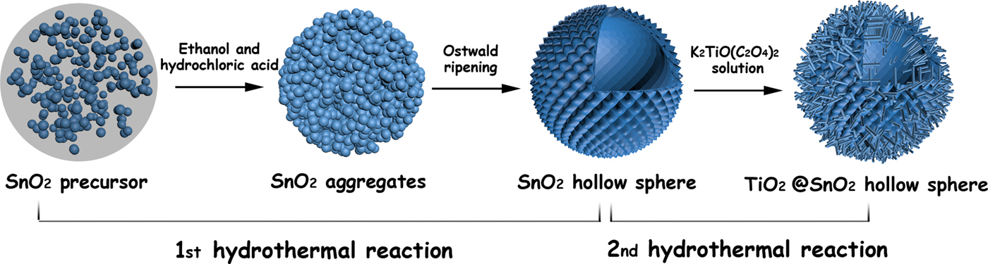
Scheme 1. The schematic of the formation processes for the SnO2 HSs and the subsequent growth of TiO2 NWs on the surface of SnO2 HSs.
Table II. Comparison of short-circuit current density (J sc), open-circuit voltage (V oc), fill factor (FF), and power conversion efficiency (η) of solar cells with SnO2 HS and SnO2 HS–TiO2 NW as photoanodes, respectively.
Conclusions
TiO2 NW-modified SnO2 HSs was prepared using a sequential template-free hydrothermal method for the first time, while pure and high crystallinity product were obtained. During the hydrothermal reaction process, the specific area of the photoanode was significantly increased by the formation of TiO2 NWs, while the surface defects of SnO2 was dramatically reduced by the interfacial passivation effect. Therefore, the dye loading and light harvesting of the composite photoanode were enhanced, while the charge recombination was successfully suppressed. Consequently, the power conversion efficiency of the solar cell based on such TiO2 NW-modified SnO2 HS photoanode reached 2.9%, which represented six time enhancement as compared with the DSCs with SnO2 HS electrodes.
Acknowledgments
This work was supported by the “thousands talents” program for pioneer researcher and his innovation team, China. This work was also supported by the National Science Foundation of China (grant numbers 51374029 and 91433102), Program for New Century Excellent Talents in the University (grant number NCET-13-0668), Fundamental Research Funds for the Central Universities (grant number FRF-TP-14-008C1), and China Postdoctoral Science Foundation (grant number 2014M550675).


