


Introduction
In early 2002, the Larsen B Ice Shelf, Antarctica, disintegrated into thousands of pieces over just a few weeks (Scambos and others, Reference Scambos, Hulbe, Fahnestock, Domack, Burnett, Leventer, Conley, Kirby and Bindschadler2003). Efforts to understand how and why this event occurred (Banwell and others, Reference Banwell, MacAyeal and Sergienko2013; Robel and Banwell, Reference Robel and Banwell2019; Leeson and others, Reference Leeson, Forster, Rice, Gormelen and van Wessem2020), and what circumstances could lead to the disintegration of other ice shelves in the future, as well as the timing of such events, have failed to reach a consensus. To some degree, this shortcoming is because many of the diverse physical mechanisms needed to understand ice-shelf disintegration are studied in isolation from the other relevant physical processes. Here, we develop a methodological framework for coupling horizontal ice-shelf flow processes with vertical ice-shelf flexure processes. By doing this, we create a framework that allows investigation of an ice-shelf stress regime that is simultaneously forced by two generators of stress: (i) large-scale ice-shelf flow; and (ii) ice-shelf flexure.
The physical mechanisms proposed to be involved in the disintegration of Larsen B Ice Shelf in 2002 include:
1. Hydrofracture by surface meltwater of existing surface crevasses, causing crevasses to propagate vertically and become rifts (e.g. Scambos and others, Reference Scambos, Hulbe, Fahnestock, Domack, Burnett, Leventer, Conley, Kirby and Bindschadler2003; Lai and others, Reference Lai2020). This process can also encourage sudden, cooperative drainage of surface lakes which, through the hydrostatic rebound of the ice shelf thus unloaded of lake water, and associated flexure, ignites a chain-reaction of lake drainage, fracture and further rifting (e.g. Banwell and others, Reference Banwell, MacAyeal and Sergienko2013; Robel and Banwell, Reference Robel and Banwell2019).
2. Break down of a compressive arch in the stress regime associated with the ice shelf's seaward flow, leading to pervasive tensile stresses that allow fracture (Doake and others, Reference Doake, Corr, Rott, Skvarca and Young1998).
3. Continuum damage mechanics processes coupled to large-scale horizontal stress features (e.g. Borstad and others, Reference Borstad2012; Lhermitte and others, Reference Lhermitte2020).
4. Iceberg capsize both within and in front of an advancing calving front (MacAyeal and others, Reference MacAyeal, Scambos, Hulbe and Fahnestock2003), iceberg capsize tsunamigenesis and cooperative iceberg capsize (Guttenberg and others, Reference Gutttenberg2011; Burton and others, Reference Burton, Cathles and Wilder2013).
5. Sea swell, potentially coupled with band gaps in ice-shelf wave transmissivity, thereby concentrating swell energy at the ice front (Freed-Brown and others, Reference Freed-Brown, Amundson, MacAyeal and Zhang2012; Banwell and others, Reference Banwell2017; Massom and others, Reference Massom2018).
6. Loss of soft, stabilizing basal marine ice (Kulessa and others, Reference Kulessa, Jansen, Luckman, King and Sammonds2014).
This list also includes the many ideas related to fracture mechanics and rupture (e.g. van der Veen, Reference Van der Veen1998; Lai and others, Reference Lai2020). The purpose of our study is to develop a coupled set of governing equations that allows the investigation of all these mechanisms.
Our approach is to modify the traditional reduced-order ice shelf model (Thomas, Reference Thomas1973; Morland, Reference Morland, Van der Veen and Oerlemans1987; MacAyeal, Reference MacAyeal1989; Weis and others, Reference Weis, Greve and Hutter1999; Hindmarsh, Reference Hindmarsh2004), which involves three variables (two horizontal flow velocities and ice thickness), by including a fourth variable: the vertical deflection of the ice-shelf due to flexure induced by bending moments caused by a variety of forcings. These forcings include the effects of compressive stress against ice-rumple grounding lines (Matsuoka and others, Reference Matsuoka2015; De Rydt and others, Reference De Rydt, Gudmundsson, Nagler and Wuite2019), cumulative thicknesses of ice added or subtracted at the surface and base (Sergienko, Reference Sergienko2013; Le Brocq and others, Reference Le Brocp2013; Banwell and MacAyeal, Reference Banwell and MacAyeal2015; Dow and others, Reference Dow2018; Macdonald and others, Reference Macdonald2019), movement of surface meltwater loads (Banwell and others, Reference Banwell, Willis, Macdonald, Goodsell and MacAyeal2019), as well as more exotic effects such as: thermally generated bending moments (Bažant, Reference Bažant1992), atmospheric pressure gradient effects (e.g. Ross, Reference Ross1854), bending moments induced by horizontal gradients in the depth-variation of ice density, dynamic changes to the ocean surface from tides (Rosier and others, Reference Rosier and Gudmundsson2018), long-period swell (Sergienko, Reference Sergienko2017), geostrophic circulation changes, and bending moments generated at ice fronts (Reeh, Reference Reeh1968; Christmann and others, Reference Christmann, Müller and Humbert2019) and grounding lines (e.g. Schoof, Reference Schoof2011; Sayag and Worster, Reference Sayag and Worster2011; Glasser and Gudmundsson, Reference Glasser and Gudmundsson2012).
In the development here, we: (i) derive the governing equations of the shallow-shelf approximation (part of a broader scheme of approximation referred to as the SSA, which includes shallow-sheet and shallow-stream approximations) for the case where an ice shelf is not in local flotational equilibrium; (ii) derive a thin viscoelastic plate treatment for ice-shelf flexure and (iii) modify the traditional treatment of mass balance to embrace cumulative build-up or decay of surface and basal ice loads. By flotational equilibrium, we are referring to the situation where each local ice column of a small surface area displaces exactly its weight in seawater (i.e. Archimedes principle). Where an ice-shelf is not in flotational equilibrium, the surface elevation will not be related to the ice thickness by the familiar expression involving the densities of ice and seawater. Generally speaking, we expect the ice shelf as a whole to be in flotational equilibrium, and areas, where it is not in flotational equilibrium, will be limited to smaller-scale regions (e.g. 10 km and less) where bending moments are significant. Our focus will be on processes within the ice shelf interior, away from the ice front and grounding zones, where the SSA is not applicable. In circumstances where the SSA applies to both sides of a grounding zone, such as the junction between an ice stream that is sliding over a highly lubricated bed and an ice shelf, our treatment is assumed to be applicable.
Following the derivation of the equations, we conduct two demonstration simulations using our viscoelastic treatment and implemented it using the finite-element package Comsol™. The simulations are highly idealized and intended to demonstrate behaviors rather than study specific phenomena in depth. We first simulate relict pedestalled lake features (Macdonald and others, Reference Macdonald2019) associated with strong spatially variable surface ablation on debris-covered ice shelves such as the McMurdo Ice Shelf (McMIS), Antarctica. Our second simulation is of ice-shelf viscous buckling, with an eye toward demonstrating how phenomena such as ice rumples (Matsuoka and others, Reference Matsuoka2015; De Rydt and others, Reference De Rydt, Gudmundsson, Nagler and Wuite2019) and traveling lakes (LaBarbera and MacAyeal, Reference LaBarbera and MacAyeal2011) may form on ice shelves.
Underlying approach
Our goal is to couple the reduced-order shallow-shelf treatment of horizontal ice-shelf flow with the reduced-order thin-plate treatment of viscoelastic flexure. The SSA is a well-known, successful description of the large-scale, long-time ice-shelf flow. The thin-plate approximation is also a well known and successful description of ice-shelf flexure phenomena. The two are ‘orthogonal’ in the sense that the vertical variations in the shallow-shelf approximation are higher-order, but in the thin-plate approximation they are the lead order. The two approximations, however, deal with the vertically integrated momentum (SSA) and bending moment (thin plate) balances. Although we develop the coupling between shallow-shelf flow and the thin-plate flexure in detail here, our treatment also applies to cases where the shallow-stream approximation (MacAyeal, Reference MacAyeal1989) is used to simulate coupled ice-stream/ice-shelf flow across a grounding zone that is an internal boundary of the system. The shallow-stream approximation is very similar to the shallow-shelf approximation but it involves a fixed basal elevation determined by bed topography and a basal friction coefficient.
We achieve the goal of coupling the SSA to the thin-plate approximation by following the approach of various asymptotic analyses in the past which justify dropping terms in the kinematics and dynamics of thin-shelves and thin-plates that are of order $\epsilon ^2$ (${\cal O}( \epsilon ^2)$
 ) and smaller (MacAyeal, Reference MacAyeal1989; MacAyeal and others, Reference MacAyeal, Sergienko and Banwell2015), where $\epsilon \ll 1$
 is the ratio of typical thickness to typical horizontal scale. Our treatment is designed to be applicable to interior regions of ice shelves away from boundaries where short-length-scale processes are active, such as ice fronts (e.g. Christmann and others, Reference Christmann, Müller and Humbert2019), side walls where ice abuts an ice-free land boundary, and grounding lines (e.g. Schoof, Reference Schoof2011; Sayag and Worster, Reference Sayag and Worster2011), where the ice flow is treated by the shallow-shelf approximation on one side and the shallow-stream approximation (MacAyeal, Reference MacAyeal1989) on the other. For research interested in local-scale boundary processes, we recommend using a full-Stokes treatment.
Kinematic assumptions
We begin by defining $x$ and $y$
 as horizontal coordinates, $z$
 as the vertical coordinate aligned with the acceleration of gravity $g$
 at the Earth surface and zero at the undisturbed long-time sea level, and $t$
 as time. The vertical dimensions of the ice shelf are described by surface and basal elevations $S( x,\; \, y,\; \, t)$
 and $B( x,\; \, y,\; \, t)$
 , respectively, and ice thickness $H( x,\; \, y,\; \, t) = S - B$
 . At time $t = 0$
 , we assume that the ice shelf is in an undisturbed state with no flexure and is floating such a way as to satisfy Archimedes principle on a local basis (where each vertical ice column, no matter how small in horizontal surface area, displaces a weight of seawater equal to its own weight). We call the state of the ice shelf when floating in this way ‘flotational equilibrium’, which is when:


where $\bar \rho _i( x,\; \, y,\; \, t)$ is the vertical average of the ice density $\rho _i( x,\; \, y,\; \, z,\; \, t)$
 , and $\rho _{sw}$
 is the density of seawater. Using the familiar averaging operator:

where $\zeta$ is an alternative $z$
 -coordinate that is zero at the middle surface of the ice shelf, half way between the surface and base,

At $t = 0$ , we assume that the initial ice thickness is $H( x,\; \, y,\; \, t = 0) = h( x,\; \, y)$
 and that as time progresses, $H$
 will be given by:

where ${\cal H}_s$ and ${\cal H}_b$
 are the cumulative amounts of ice thickness gained at the surface and the base of the ice shelf since $t = 0$
 . (A restatement of mass balance equations comes in the following section.) At times greater than zero, the surface and basal elevations are described by:


where $\eta$ is the cumulative change in the $z$
 elevation of the ice shelf's middle surface (neutral surface) at $t = 0$
 for $t> 0$
 (when the addition of cumulative ice thicknesses ${\cal H}_s$
 and ${\cal H}_b$
 at the top and bottom, and the effect loads and bending moments begin to take effect). The ice shelf is defined to be flexed when, except for short term effects of waves and bobbing, $S$
 and $B$
 do not have the flotational equilibrium values given by Eqns (1a) and (1b). We further write $\eta$
 as the sum of a viscous part $\eta _v$
 , an elastic part $\eta _e$
 and an ice-shelf area mean part $\bar {\eta }^{x, y}$
 ,
,

The terms $\bar {\eta }^{x, y}$ and ${\bar \eta }^\circlearrowleft$
 are required to satisfy the constraint that the entire ice shelf is, on average, in flotational equilibrium:

and to account for the possibility that surface and basal accumulation will rotate, or tilt, the ice shelf about a horizontal axis while keeping it in flotational equilibrium as a whole:

where $A$ is taken to be the area of the ice shelf, and the operator $\chi ^\circlearrowleft ({\cdot})$
 represents the averaging operator needed to resolve what parts of ${\cal H}_s$
 and ${\cal H}_b$
 satisfy the condition of perfect ice shelf tilting. The displacements $\bar {\eta }^{x, y}$
 and ${\bar \eta }^\circlearrowleft$
 are understood to induce no curvature to the middle surface ice shelf, and thus do not induce flexure stresses. This is why we consider spatially non-uniform surface and basal accumulation to be a process that generates flexure, which is embodied by $\eta _v$
 and $\eta _e$
 .
.
Stress and strain rate
Having described our definitions of ice-shelf geometry and state of flotation both when flexure effects are present and when they are not, we turn to describing the velocity and strain rate of the ice shelf based on the common assumptions of shallow-shelf and thin-plate approximations described in previous studies (Love, Reference Love1888; MacAyeal, Reference MacAyeal1989). We refrain from describing displacement and strain associated with elastic deformation, but it is similar (MacAyeal and others, Reference MacAyeal, Sergienko and Banwell2015). The key assumption is that the square of the ice-shelf aspect ratio $\epsilon$ , defined to be the ratio of typical ice thickness to the typical horizontal extent of the ice-shelf phenomena of interest, is much less than 1. This assumption allows terms in quantities that are ${\cal O}( \epsilon ^2)$
 and smaller to be disregarded in formulating the governing equations.
We define $u$ and $v$
 to be the $x$
 and $y$
 horizontal velocities, $w$
 to be the vertical velocity, and $\dot {{\bf e}}$
 to be the strain-rate tensor (bold faced variables are considered to be vectors or tensors). Considering one component of the horizontal velocity, $u$
 , we make the following decomposition based on our application of shallow-shelf and thin-plate assumptions:

where $\dot e_{xz}$ is a vertical shear component of strain rate given by:

We note that the term ${\partial w}/{\partial x}$ does not appear in the above equation, because it is considered to be ${\cal O}( \epsilon ^2)$
 . To identify vertical shear with just the vertical gradient of the horizontal velocity is common in shallow-shelf, shallow-sheet and thin-plate applications.
Considering only the viscous component of ice-shelf flexure, the vertical strain rates are generated by the rate of change of the viscous component of $\eta$ , which is $\eta _v$
 :
:

where $\dot \eta _v$ is the time-derivative of $\eta _v$
 . With this relationship, Eqn (9) may be written:

We next consider the horizontal strain rate component $\dot e_{xx}$ , which, given Eqn (11) is expressed as a sum:

All the other components of velocity and strain rate are partitioned as sums in the same manner. We note that the second term on the right-hand side of the above equation depends on $\zeta$ . This means that this term's average over depth is zero, and it does not contribute directly (by integration over $z$
 ) to the depth-averaged horizontal flow of the ice shelf.
The stress within the ice shelf is determined by gravity (giving pressure $p$ a glaciostatic term) and by deviatoric stress ${\bf T}$
 that is related to the strain rates by the constitutive relation for ice. To illustrate just one deviatoric stress term, we consider $T_{xx}$
 :
:

where $\nu ( x,\; \, y,\; \, z,\; \, t)$ is a flow-law and ice-parameter (e.g. temperature, ice stiffness parameters) dependent effective viscosity, and we have dropped $< {\cal O}( \epsilon ^2)$
 -terms from the sum. If we take $\nu ( x,\; \, y,\; \, z)$
 to be the sum of its mean over depth and an arbitrary extra function that has no mean (which accounts for variations of ice temperature and stiffness parameters with $z$
 ):
):

where ${\cal S}( \zeta )$ (not to be confused with ice shelf surface elevation $S$
 ) is a function with no mean (i.e. $\bar {{\cal S}}( \zeta ) = 0$
 ). Substitution of this expression for $\nu$
 into Eqn (14) gives:

For the depth-average part of the above stress component, we have

In the above expression, we see two viscosity-like parameters, $\bar \nu$ and $\overline {\zeta {\cal S}( \zeta ) }$
 . Normally, in shallow-shelf flow without flexure, $\bar \nu$
 is the effective viscosity that determines the flow. Here, we see as a first-element of coupling that an additional viscosity parameter is involved, namely $\overline {\zeta {\cal S}( \zeta ) }$
 .
.
We now consider the bending moment ${\bf M}$ . We assume a Maxwell style of viscoelasticity in our treatment of flexure, and so both the elastic and the viscous parts of $\eta$
 respond to the same single bending moment, like how a spring and a viscous attenuating piston/cylinder device (dashpot) respond to a force when connected in series. Here we consider how $\eta _v$
 , the viscous part of $\eta$
 , depends on $M_{xx}$
 :
:

We note that the above expression for bending moment depends on three measures of ice viscosity, the depth average viscosity $\bar \nu$ and two measures $\overline {{\cal S}\zeta }$
 and $\overline {{\cal S} \zeta ^2}$
 that depend on the variation of viscosity with $\zeta$
 . We thus anticipate that the viscosity that primarily governs shallow-shelf flow, $\bar \nu$
 , will be different from the viscosity that governs flexure, although this is not the case when ${\cal S} = 0$
 , i.e. the ice is of constant viscosity.
If viscosity variation with $\zeta$ is presumed to be zero, a simpler expression for $M_{xx}$
 emerges. We record this expression for use in describing the demonstration simulations in sections below:

To proceed further with deriving the bending moment $M_{xx}$ we need to determine the pressure $p$
 . We start with the vertical stress balance:

As is customary in shallow-shelf and thin-plate approximations we drop the vertical shear terms (assuming they are ${\cal O}( \epsilon ^2)$ or smaller, and substitute for $T_{zz} = 2 \nu ( {\partial w}/{\partial \zeta })$
 :
:

We next invoke the incompressibility condition and the definitions of $\dot e_{xz}$ and $\dot e_{yz}$
 in terms of the $x$
 and $y$
 derivatives of $\eta$
 ,
,

to give:

We define the density, like the viscosity, to be the sum of its depth-average and a term that varies with $\zeta$ :
:

where $\bar {{\cal R}} = 0$ . Integrating Eqn (23) over the vertical, from a lower limit of $\zeta$
 to an upper limit of $\displaystyle {H}/{2}$
 where we apply the boundary condition that atmospheric pressure is zero, we obtain:

which gives:

We record for future use the depth average of $p$ :
:

For future reference, if the depth variation of viscosity and ice density are zero, i.e. ${\cal S} = 0$ and ${\cal R} = 0$
 we obtain:

which gives for the depth-average pressure:

We can now compute the contribution of the pressure to the bending moment using the simplified form in Eqn (28):

This then renders the expression obtained previously (Eqn (19)) into the following form:

For what follows, we note that components of ${\bf M} = [ M_{xx} \ M_{yy} \ M_{xy} ] ^T$ are related to the second derivatives of $\dot \eta _v$
 by the following linear relation when we disregard $\zeta$
 variations in ice viscosity and density, i.e. when ${\cal S}( \zeta ) = 0$
 and ${\cal R}( \zeta ) = 0$
 , respectively (as we shall assume in our demonstration simulations in sections below):

where we have added the subscript $v$ in the above expression to differentiate the bending moment due to viscous stresses from those due to glaciostatic (subscript $g$
 ) and elastic (subscript $e$
 ). The glaciostatic contribution to the bending moment expressed as

will be treated as a forcing term to the vertical force balance equation (derived in the section presenting our treatment of flexure below), because it does not depend on $\eta$ . We note that the above expression for $M_g$
 is not written with terms that depend on $\overline {( \zeta {\cal S}) }$
 or ${\cal R}( \zeta )$
 , however, these terms could be very important in situations where ice shelves have voids or englacial water that disturbs the viscosity and density structure with depth. Such a situation is envisioned for Arctic ice shelves such as the Milne Ice Shelf, where channelized englacial water bodies and voids are detected, and which may contribute to the pervasive rumpling of the ice shelf (Rajewicz, Reference Rajewicz2017).
To avoid repeating the similar, but lengthy, derivation of the elastic contribution for the bending moment ${\bf M}_e$ , we simply record it here:

where $E$ is the Young's modulus and $\mu$
 is Poisson's ratio, which we assume to be constants. (We do not consider their variation with depth in this study, however, such consideration, if warranted, would follow the above treatment for how ice viscosity and density vary with depth.)
The linear operator expressions are given above for ${\bf V}$ and ${\bf D}$
 will be used in the section below on developing the coupled treatment of ice-shelf flow and flexure. They will also be used in the demonstration simulations presented below. We reiterate, however, that the linear operators given above have been simplified under the assumption that contributions from ${\cal S}$
 and ${\cal R}$
 , representing vertical variations in viscosity and density, are zero. Full consideration of variable viscosity and density is relegated to applications that go beyond simple demonstrations.
Ice rheology in the coupled system
As indicated above, the depth-averaged stress appearing in the SSA depends on the depth-averaged effective ice viscosity, and the bending moment depends on both the depth average of, and the first moment of, the effective ice viscosity. This difference can be understood by considering the situation where an anomalously viscous ice layer (e.g. because of temperature or ice impurity) exists at the ice-shelf middle surface. This viscosity anomaly will contribute to a depth average, but not to the first moment. In this study, we do not seek to clarify or demonstrate the effects of ice rheology, e.g, specific variation of effective viscosity with $\zeta$ caused by the flow law and by other effects such as temperature. We thus proceed in the demonstration simulations below to use two different Newtonian viscosities for ice, one that is the depth average $\bar \nu$
 relating to the SSA and one that includes an arbitrary (for our demonstrations) additional viscosity variation used for the thin-plate approximation which we call $\nu _f$
 . In the case of the ice-rumple demonstration presented in the following section, we find that it is convenient to have $\nu _f < \nu$
 for the ad hoc way in which we set up the simulation. This could, for example, be explained by ice near the upper and lower surfaces of the ice shelf having lower viscosity than in the centre (i.e. near the middle surface) where the ice is colder.
Pre-stressing of newly accumulated ice layers
In the foregoing derivation, we have focussed on computing bending moments via the integral:

Let us consider what happens when, at $t = 0$ , the ice thickness is changed from $h$
 to $h + {\cal H}_s$
 through the instantaneous addition of an accumulated layer of ice ${\cal H}_s$
 . Let us further suppose that at $t = 0$
 the ice shelf is in a state of flexure so that $\eta \ne 0$
 and bending moments exist within it. The new addition of ice ${\cal H}_s$
 is added by a process (e.g. snow fall and densification) that does not introduce intrinsic bending moments. This means that the original part of the ice shelf contained within the thickness $h$
 is pre-stressed, and the new part of the ice shelf contained within the thickness ${\cal H}_s$
 is stress-free. As $t> 0$
 this disparity between the old and new ice will mean that for the old ice to deform viscoelastically toward its equilibrium shape, it must deform the new ice from its deposited, stress-free shape. This is a bit like pre-stressing in concrete or metallurgy. The proper way to account for this is to track each layer of the ice shelf as it is added. And this can be done via a full Stokes treatment. Since our intention is to reduce complexity, we deal with this subtle problem by assuming that any new ice added to the ice shelf instantaneously inherits the stress state of the ice shelf that it joins.
Modification of the shallow-shelf approximation
The SSA (Muszynski and Birchfield, Reference Muszynski and Birchfield1987; Morland, Reference Morland, Van der Veen and Oerlemans1987; MacAyeal, Reference MacAyeal1989; Weis and others, Reference Weis, Greve and Hutter1999; Hindmarsh, Reference Hindmarsh2004) is a diagnostic, time-independent set of depth-integrated stress balance equations for two depth-independent horizontal velocities, $\bar u$ and $\bar v$
 (MacAyeal, Reference MacAyeal1989). Here we derive these equations under the assumption that the ice shelf is not in flotational equilibrium, i.e.:

due to a non-zero flexure ($\eta \ne 0$ ).
).
The stress-balance equations for $x$ and $y$
 are written:


We next integrate the above equations over $z$ , noting the definitions of $\bar \nu$
 and $\bar p$
 , recognizing that $u$
 and $v$
 are independent of $z$
 , and use Leibniz rule:


We now make use of boundary conditions on the horizontal stress at $z = S,\; \, \ B$ , and substitute for the depth-averaged deviatoric stress and pressure using Eqns (17) and :


where ${\bf T}_f$ is the full stress tensor (sum of deviatoric stress ${\bf T}$
 and pressure $p {\bf I}$
 , where ${\bf I}$
 is the identity matrix) given by:

and ${\bf n} = [ n_x \ n_y \ n_z ] ^{T}$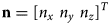 is the normal to the surface in question. Noting that


we can substitute the boundary conditions of Eqns (39a) and (39b) for the terms on the right-hand sides of Eqns (38a) and (38b):


We next make use of Eqns (17) and (27) to substitute for $\bar p$ :
:


We simplify the above expression by collecting terms that depend on ${\cal R}( \zeta )$ and second derivatives of $\dot \eta _v$
 onto the right-hand side of the equations and calling them coupling terms $C_x( \dot \eta _v)$
 and $C_y( \dot \eta _v)$
 :
:


We will take $C_x = C_y = 0$ in our demonstration simulations in sections below because these coupling terms depend on $\overline {\zeta {\cal S}}$
 which is zero under the assumption that the vertical variation in viscosity is zero, i.e. when ${\cal S} = 0$
 . We also anticipate that the coupling terms will likely be small and restricted to small regions of the ice shelf because $\dot \eta _v$
 will likely be related to localized processes and may be periodic with zero mean over long horizontal distances.
Boundary conditions used to solve the shallow-shelf approximation for $u$ and $v$
 here are the specification of $u$
 and $v$
 at grounding lines and other land-constrained boundaries of the ice shelf, and a stress condition at the seaward ice front:


where ${\bf n} = [ n_x \ n_y] ^T$ is the outward pointing normal to the ice front in the $x,\; \, y$
 plane. We note that the right-hand sides of Eqns (45a) and (45b) involve the variable $B( x,\; \, y,\; \, t)$
 which is the elevation of the ice-shelf bottom, and for which its absolute value is the ice-shelf draft. Like $S$
 , $B$
, $B$ is not assumed to be related to $H$
 by the flotation equilibrium relationship wherever flexure is present.
Governing equations for flexure
The purpose of this section is to determine the change in vertical elevation of the ice shelf due to flexure effects, namely, ${D \eta }/{D t}$ , where ${D}/{D t} = ( {\partial }/{\partial t}) + {\bf u} \cdot \nabla$
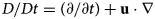 is the material time derivative, ${\bf u} = [ u \ v] ^T$
 and $\nabla = ( {\partial }/{\partial x}) + ( {\partial }/{\partial y})$
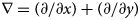 , from the thin-plate theory of vertical force balance of Kirchhoff and Love (Love, Reference Love1888) (see also Slim and others (Reference Slim, Teichman and Mahadevan2012); Ribe (Reference Ribe2003)) and from the forcings that cause the ice shelf to deviate from flotational equilibrium on a local basis. Given that $\eta = \eta _v + \eta _e + \bar {\eta }^{x, y} + \bar \eta ^{\circlearrowleft}$
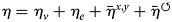 , we anticipate that $\eta _v$
 and $\eta _e$
 will be determined by the governing equations of thin-plate theory. We do not develop expressions for ${D \bar \eta ^{x, y}}/{D t}$
 and ${D \bar \eta ^\circlearrowleft }/{D t}$
 , because, as noted above, these do not contribute to flexure. In what follows, we shall assume $\bar {\eta }^{x, y} = \bar \eta ^\circlearrowleft = 0$
 for notation convenience.
Vertical force balance due to bending moments
The vertical force balance on ice columns in the ice shelf is used to determine ${{D \eta _v}/{D_t}}$ and ${{D \eta _e}/{D t}}$
 . In this balance, the divergence of bending moment gradients is equal to the sum of vertical force acting on the ice shelf (Love, Reference Love1888; Slim and others, Reference Slim, Teichman and Mahadevan2012):

where ${\bf M} = [ M_{xx} \ M_{yy} \ M_{xy} ] ^T$ is a column vector of bending moments (the order of appearance of its elements has no physical meaning, but is defined for convenience), and $f$
 is the sum of forces acting vertically on the plate. We shall further adopt the convention that terms depending on the glaciostatic part of the bending moments ${\bf M}_g$
 will be written as a forcing term in the expression for $f$
 , to be discussed below. This is because ${\bf M}_g$
 does not depend on $\eta$
 . Our first assumption is that the flexure of an ice-shelf is quasistatic, we thus drop the acceleration term on the left-hand side of Eqn (46).
Referring to Eqns (32) and (34), we write:


By the definition $\eta = \eta _v + \eta _e$ (and assuming that $\bar {\eta }^{x, y} = \bar \eta ^\circlearrowleft = 0$
 ), we can write:

Substitution of the expressions in Eqns (47a) and (47b) into the above equation gives:

This equation forms the constitutive relation used in our formulation.
In other examples of the application of the viscoelastic constitutive relation in a linear form, such as by Rosier and others (Reference Rosier and Gudmundsson2018), the constitutive relation appears as:

where $c_1$ and $c_2$
 are constants, and the overset triangle denotes the upper convective time derivative (Oldroyd time derivative), having as its leading term the material time derivative indicated by the overdot. We do not use the upper convective time derivative, because its extra terms account for large-amplitude flexure which rotate the neutral surface of the viscoelastic plate significantly out of horizontal. We anticipate that ice-shelf flexure will be of low amplitude and that we may assume that components of stress, strain and strain-rate tensors with indices $xx$
 , $yy$
 and $xy$
 can still represent these tensor components on the neutral surface, which will only be slightly tilted out of horizontal.
One final modification is made to the constitutive relation to avoid mixing time derivatives of ${\bf M}$ with undifferentiated ${\bf M}$
 in the same equation. We introduce a new variable of convenience, which we shall refer to as a ‘generating potential’, $\mathbf \Phi = [ \Phi _1 \ \Phi _2 \ \Phi _3] ^{{\bf T}}$
 :
:

This allows Eqn (49) to be written in a manner where all terms are time differentiated:

or

Integration over $t$ gives,

where we assume the constant of integration to be zero. This assumption is equivalent to assuming that at some initial time (the lower bound of the integration at $t = 0$ ), there are no viscous contributions to bending moment.
We summarize the full formulation of flexure based on the many assumptions and on our novel approach to working with bending moment and $\eta$ as the principle variables:


where ${\bf H}$ is defined as

Normally, in derivations such as those presented here, the effort is to replace the bending moments with terms involving second derivatives of $\eta$ . This then yields a single equation that is fourth order in spatial derivatives of $\eta$
 when ${\bf u}$
 is zero; and fifth order if ${\bf u} \ne 0$
 . We prefer to work with the system of three equations written above because its largest spatial derivatives are only second order, and this conforms well with the capabilities of Comsol™, which requires all equations of higher than second order spatial derivatives be divided into systems of equations having lower-order spatial derivatives.
We note that our formulation is intended for both short-timescale (seconds to days) and long-timescale processes (years). An argument can be made that, in the case of processes with long timescales, it is unnecessary to retain the elastic part of the viscoelastic constitutive relation we propose here. This may be true. We note, however, that treatment of both elastic and viscous behavior introduces only additional coefficients to the governing partial differential equations (PDEs) expressed above, not new variables; so elastic treatment comes without significant computational cost even if the phenomenon of interest is dominated by the viscous part of flexure. Also, in some applications, such as the differential-ablation phenomena we will discuss in the demonstration simulations below, elastic deformation is introduced to the ice shelf continuously with time (e.g. with each day's spatially variable melting and water movement); and thus elastic effects cannot be so easily separated from viscous effects based on their short-term importance even when the phenomena evolve over many cycles of the viscoelastic relaxation time, commonly referred to as the Maxwell timescale. Finally, the initial elastic response may determine length scales of features that subsequently evolve through viscous deformation. The elastic response, thus, may provide an initial condition for the time-dependent viscous flexure which would otherwise develop differently in the absence of elasticity.
Flexure forcing
The physical meaning of Eqn (55a) is the balance of bending moments and forces $f( x,\; y,\; t)$ caused by a number of physical processes. We represent these processes in the following sum:


We describe each term in the sum on the right-hand side in order from a to i in Eqns (57a)–(57i):
a. The restoring force of buoyancy acting on the initial ice thickness $h$
 .
.b. The buoyancy of accumulated mass between the base and the flotational equilibrium value of the basal elevation. This depends on spatial gradients in ${\cal H}_s$
and ${\cal H}_b$ and spatially inhomogeneous basal accumulation. This term arises, for example, in the creation of basal channels (Le Brocq and others, Reference Le Brocp2013; Alley and others, Reference Alley, Scambos, Siegfried and Fricker2016) and inhomogeneous marine ice deposition (Koch and others, Reference Koch, Fitzsimons, Samyn and Tison2015).c. The weight of accumulated mass between the surface and the flotational equilibrium value of the surface elevation. This term arises, for example, in the creation of surface channels (Dow and others, Reference Dow2018, Boghosian, personal communication, 2020).
d. The effect of additions or subtractions of surface meltwater (where $\rho _w$
is the density of fresh meltwater). This term arises, for example, where there are filling and draining supraglacial lakes (Banwell and MacAyeal, Reference Banwell and MacAyeal2015; MacAyeal and others, Reference MacAyeal2015; Banwell and others, Reference Banwell, Willis, Macdonald, Goodsell and MacAyeal2019; Robel and Banwell, Reference Robel and Banwell2019) and dolines (Moore, Reference Moore1993; Bindschadler and others, Reference Bindschadler, Scambos, Rott, Skvarca and Vornberger2002).e. The effect of the membrane (horizontal ice-shelf flow) stresses associated with ice-shelf flow having a vertical component when there is acurvature in the middle surface of the ice-shelf (Ribe, Reference Ribe2003; Slim and others, Reference Slim, Teichman and Mahadevan2012). This term arises when there is a second derivative of $\eta$
, because a ‘horizontal section’ of the ice shelf which has vertical sides when unflexed will have both its sides tilt slightly ‘face down’ or ‘face up’ when curved. This means that the membrane stress will have a slight vertical coordinate. This term is expected to be important when there are strong compressive membrane stresses in the ice shelf, such as at ice rumples (Matsuoka and others, Reference Matsuoka2015; De Rydt and others, Reference De Rydt, Gudmundsson, Nagler and Wuite2019) and traveling lakes (LaBarbera and MacAyeal, Reference LaBarbera and MacAyeal2011).f. The effect of glaciostatic pressure generated bending moments (derived in a previous section). This term is expected to be important where there are large second derivatives of ice thickness and significant variations of ice density with depth, such as in the case of the Milne Ice Shelf (Rajewicz, Reference Rajewicz2017).
g. The effect of thermal stresses ($\theta$
is temperature). This can be important where ice is thin and there is a significant annual or diurnal cycle in surface temperature (Sanderson, Reference Sanderson1978; Bažant, Reference Bažant1992; MacAyeal and others, Reference MacAyeal2015, Reference MacAyeal2017).h. The effects of atmospheric pressure gradients $p_a( x,\; \, y,\; \, t)$
which bear down on the upper surface of the ice shelf such as the inverse barometer effect (Ross, Reference Ross1854).i. The effects of ocean dynamic topography $h_d( x,\; \, y,\; \, t)$
changes due to tides (Rosier and others, Reference Rosier and Gudmundsson2018) and sea swell (Sergienko, Reference Sergienko2010, Reference Sergienko2017).


Flexure is also forced by boundary conditions, such as at grounding lines (Schoof, Reference Schoof2011; Glasser and Gudmundsson, Reference Glasser and Gudmundsson2012; Rosier and others, Reference Rosier and Gudmundsson2018) and ice fronts (Reeh, Reference Reeh1968; Hindmarsh, Reference Hindmarsh2012; Christmann and others, Reference Christmann, Müller and Humbert2019); however, we do not focus on this well known forcing in this study.
In the present study, our focus is on the first, third and fifth terms of the right-hand side of Eqns (57a)–(57i). We thus relegate to future research determination of how relevant the other forcing terms are to ice-shelf behavior, and to what processes they pertain. The second term of Eqns (57a)–(57i) controls the response to accumulation and ablation, and especially their gradients in situations where ablation causes surface channels to incise into the ice shelf, and where debris cover (e.g. the McMIS, Antarctica), and its absence in limited areas, cause pedestalling of high-albedo surfaces (e.g. pedestalled, relict lakes, Macdonald and others, Reference Macdonald2019). The fourth forcing term is of interest when the ice-shelf flow stresses are compressive and give rise to viscous buckling instability that leads to ice rumples along grounding lines where ice flows toward, rather than away from, the grounding line.
To solve the above formulation of viscoelastic flexure, initial and boundary conditions are required. Thus we choose simple, bending moment free boundary conditions for $M$ and $\eta$
 . For the initial conditions, we will take $\eta$
 to be zero or some other function, as the case examined requires. The details of these specifications will depend on the application, as we discuss below for our demonstration simulations.
Reframing the mass balance equations
Variables needed to force the coupled flow and flexure process formulated in the previous sections are ice thickness, surface elevation and basal elevation, $H$ , $S$
, $S$ and $B$
 , respectively, and cumulative mass gained/lost at the surface and base by mass-balance processes, ${\cal H}_s$
 and ${\cal H}_b$
 , respectively. The surface and basal elevations in the situation where flexural dynamics and hydrostatic buoyancy forces can interplay are given by


where, as above, $\eta ( x,\; \, y,\; \, t)$ is the vertical displacement of the ice-shelf mid-plane in response to bending moments and changes in ice thickness associated with surface and basal accumulation, $h( x,\; \, y,\; \, t)$
 is a reference ice thickness that represents two ideas. Assuming that $\eta ( x,\; \, y,\; \, 0) = 0$
 at $t = 0$
 , $h( x,\; \, y,\; \, 0)$
 represents the initial ice-shelf thickness when in flotational equilibrium. This may be an imaginary reference state, if flexure is always present, however it is needed as the ‘seed’ from which the ice thickness $H( x,\; \, y,\; \, t> 0)$
 , surface and basal elevations $S( x,\; \, y,\; \, t> 0)$
 and $B( x,\; \, y,\; \, t> 0)$
 , and $\eta ( x,\; \, y,\; \, t)$
 evolve during $t> 0$
 . This reference thickness, for example, may be the start of a simulation of an ice shelf that has not yet encountered the forcing that causes flexure. The reference thickness $h$
 also represents what $H( x,\; \, y,\; \, t> 0)$
 would be in the absence of cumulative surface and basal accumulation/ablation since $t = 0$
 , the thicknesses of which are denoted by ${\cal H}_s( x,\; \, y,\; \, t)$
 and ${\cal H}_b( x,\; \, y,\; \, t)$
 (for ablation, ${\cal H}_s$
 and ${\cal H}_b$
 have negative values). In other words, ${\cal H}_s$
 and ${\cal H}_b$
 denote the cumulative ice accumulated or ablated which requires $\eta ( x,\; \, y,\; \, t)$
 to respond. In the absence of flexural strength (zero elasticity and viscosity), $\eta$
 is designed to change $S$
 and $B$
 to conform exactly with flotational equilibrium.
Note that, $h( x,\; \, y,\; \, t)$ obeys
obeys

This indicates that $h$ changes with time due to advection with the horizontal flow (${\bf u} \cdot \nabla h$
 ) and with flow divergence ($h \nabla \cdot {\bf u}$
 ). Accompanying this behavior in $h$
 , the cumulative thickness ice accumulated or ablated also changes with time due to advection and flow divergence:


which then gives the familiar expression for ice-shelf mass balance:

where the total ice thickness $H$ is:
is:

In the above decomposition of the familiar mass-balance equation for ice-shelf flow into three separate mass balance equations, one for each of $h$ , ${\cal H}_s$
 , and ${\cal H}_b$
 , we are keeping track of the evolution of ice thickness, but allowing the parts of that thickness, the cumulative thickness of ice gained or lost at the surface and base, to be tracked as time increases so as to allow flexure to respond to additions or subtractions of ice. That cumulative changes of thickness caused by surface and basal accumulation (ablation) is tracked explicitly using Eqns (60a) and (60b) is a key feature of our formulation, and is motivated by the fact that ice-shelf viscoelastic flexure at time $t> 0$
 proceeds in response to all accumulated changes in ice-shelf loads at times $\tau$
 where $0 < \tau \le t$
 .
.
To aid understanding of the partitioning of surface and basal mass balance into cumulative terms obeying Eqns (59) and (60a), we note the special case where bending moments are absent. In this circumstance, the sum of terms comprising $f$ in Eqn (57i) must be zero. If only the first three terms are non-zero, we have

Substitution of $\eta$ into Eqns (58a) and (58b) gives:


which, along with the relation in Eqn (62) gives the familiar result:


which is a statement of flotation equilibrium in the absence of flexure.
Numerical implementation
In the next sections, we demonstrate several idealized, preliminary applications of the formulation. These demonstrations are conducted numerically with a finite-element PDE solver set up to represent the above equations for ice-shelf flow, flexure and cumulative mass balance. The simulations are demonstrations only, and are not intended to reach specific conclusions about any of the processes demonstrated.
To conduct the numerical simulations, we used Comsol™ to implement the simulations undertaken. We use Comsol because it is optimized for easy and quick implementation of PDEs such as ours, without the attendant need to develop discretization, meshing, solving and visualization algorithms. Specifically, Comsol allows representation of general, coupled PDE's in coefficient form, which means the user simply has to specify the coefficient constants or functions that multiply each of the various generic terms of a PDE (many of which will be specified as zero). For one-dimensional (1-D) simulations, we use sextic Lagrange shape functions and a direct solver. For two-dimensional (2-D) simulations, we use cubic Lagrange shape functions on a triangular mesh and a direct solver. Further details of our numerical implementation of the governing equations in Comsol are provided in the Supplemental material.
Demonstration simulations
We conduct two idealized demonstration simulations to illustrate how the above formulation deals with two examples of ice-shelf behavior: (1) formation of pedestalled, relict lakes (Macdonald and others, Reference Macdonald2019) and (2) the formation of ice-rumples (Thomas, Reference Thomas1973; Matsuoka and others, Reference Matsuoka2015; De Rydt and others, Reference De Rydt, Gudmundsson, Nagler and Wuite2019) and traveling lakes (LaBarbera and MacAyeal, Reference LaBarbera and MacAyeal2011). These two specific phenomena are chosen because they display the effects of the third and fifth forcing terms in Eqns (57a)–(57i), respectively: pedestalled, relict lakes associated with differential ablation on debris-covered ice shelves, and ice-shelf rumpling (or viscous buckling instability) active along compressive grounding zones of some ice shelves. The first application is motivated by pedestalled, relict lakes on the McMIS where there are strong gradients in surface ablation due to superimposed high-albedo ice surrounded by debris cover (Macdonald and others, Reference Macdonald2019; Banwell and others, Reference Banwell, Willis, Macdonald, Goodsell and MacAyeal2019). The second application is motivated by the so-called traveling lakes on the George VI Ice Shelf (GVIIS) (LaBarbera and MacAyeal, Reference LaBarbera and MacAyeal2011; Banwell and others, Reference Banwell2021) and by the McDonald Ice Rumples (MIR) on the Brunt Ice Shelf (BIS) (Thomas, Reference Thomas1973; Matsuoka and others, Reference Matsuoka2015; De Rydt and others, Reference De Rydt, Gudmundsson, Nagler and Wuite2019). We present 1-D simulations of these two applications, and we also present a 2-D simulation of the second application (ice-shelf rumpling). In all demonstration runs, we specify $E = 10^9$ Pa, $\mu = {1\over 3}$
 , and take various choices for the ice viscosity $\nu$
 as discussed below.
Differential ablation: pedestalled, relict lakes
In our first idealized demonstration, we investigate the effects of spatially heterogeneous surface ablation in the context of pedestalled, relict lakes we have observed on the McMIS, Antarctica (Macdonald and others, Reference Macdonald2019; Banwell and others, Reference Banwell, Willis, Macdonald, Goodsell and MacAyeal2019) (Fig. 1). Pedestalled, relict lakes are found on debris-covered ice shelves, and each begins as a lake that forms in a debris-covered depression during one melt season. During the first winter, the lake water freezes, becoming superimposed ice that conceals the original debris cover with high-albedo ice. In subsequent years, the superimposed high-albedo ice reduces surface ablation relative to the surrounding debris-covered ice-shelf surface. This causes the surface of the surrounding ice shelf to lose mass at a rate much greater than the spatially limited zone of the original lake, now covered by superimposed ice and free of surface debris. The sharp contrast between the ablation rate at the high-albedo original lake site and the low-albedo debris-covered surroundings (Fig. 1b) leads to circumstances where the second term, ${\cal H}_s$ , in the forcing for flexure has a strong spatial gradient at the shoreline of the original lake. This is what is investigated in the second demonstration.

Fig. 1. (a) Aerial photograph (altitude $\sim 500$ m) of Ring Pedestal on the McMIS looking from North to South (Macdonald and others, Reference Macdonald2019) (photo taken in January 2016 by A. Banwell). (b) Photograph at the edge of Peanut Pedestal looking from North to South (photo taken in January 2016 by A. Banwell). The height of the pedestal at its edge is approximately 3 m, however is variable depending on local debris conditions. (c)-(e) True color pan-sharpened Landsat 7 and 8 images showing the initial lakes (c), and development of pedestalled features (d) and (e) over a 7-year period (Macdonald and others, Reference Macdonald2019).
Our demonstration simulation will consider only a cross-section of the ice shelf (along a flowline) containing a relict lake feature. The 1-D version of the ice-shelf flow, mass balance and flexure equations derived above are:


We use a 1-D domain that is 14 km long (motivated by the flowline length of the McMIS depicted in the field study map of Macdonald and others (Reference Macdonald2019)), and specify an inflow boundary condition of $u = 50$ m a$^{-1}$
 at the upstream side of the domain. Initial ice thickness is taken to be 50 m. For the ice viscosity, we take $\bar \nu = 10^{16}$
 Pa s and $\nu _f = {\bar \nu }/{2}$
 . This is an arbitrary choice, as explained above, but recognizes that the viscosity applicable in thin-plate flexure will not necessarily equal the depth-averaged viscosity applicable in shallow-shelf flow.
To simulate the effects of variable ablation at the surface, we introduce a debris cover of depth $R( x,\; \, t)$ satisfying the following equation:

with an initial condition given by,

To specify the surface ablation ($\dot A < 0$ ), we determined where $R < 0.15$
 m:
m:

This ablation rate was then used to force the equation for ${\cal H}_s$ . We assumed that basal accumulation/ablation was zero everywhere, although there is good evidence that the McMIS is sustained against surface ablation by basal freezing (Koch and others, Reference Koch, Fitzsimons, Samyn and Tison2015).
The results of a 20-year simulation of the pedestal formation process are shown in Figure 2. As seen in Figure 2a, the pedestal has an uplifted core, and is surrounded by a moat that is at a slightly lower elevation than the more distal ice shelf ablation area. The presence of the moat surrounding the pedestal suggests that surface meltwater would likely pool there, and this may be in accord with an aerial photograph of Ring Pedestal on the McMIS in 2008 shown in Figures. 3 and 1d.

Fig. 2. (a) Ice-shelf surface and basal profiles at $t = 20$ a. The basal profile has been moved up by 25 m so that the two profiles are easier to see. The pedestalled, relict lake feature stands about 2 m above the surrounding ice shelf. Its weight is mostly compensated by a larger draft indicated by the downward projection of the ice-shelf base. Some weight compensation is supported by flexure, as indicated by (b) showing the oscillations of $\eta$
 near the edges of the pedestal feature.

Fig. 3. Aerial view of Ring Pedestal in 2008, at roughly the time the Landsat 7 image of Fig. 1d. We speculate that the blue ring is the depressed area inside the highest part of the Pedestal, seen in Fig. 2. Immediately outside the blue ring is evidence of the debris cover, which is likely exposed within the wall of the moat that surrounds the pedestal. Beyond the pedestal, the surface debris is covered by a thin layer of seasonal snow. This aerial photograph was taken by Andris Apse, the artist in residence at the New Zealand Antarctic Program's Scott Base, who kindly permitted its use in this study.
Ice rumples and traveling lakes
Ice rumples and traveling lakes are viscoelastic buckling phenomena (Thomas, Reference Thomas1973; Ribe, Reference Ribe2003; LaBarbera and MacAyeal, Reference LaBarbera and MacAyeal2011; Slim and others, Reference Slim, Teichman and Mahadevan2012) evident along margins of ice shelves where both ice flow and strong compressive stress are directed toward the grounding line (Fig. 4). The ice-rumples demonstration presents a case where we assume that the shallow-shelf approximation and the shallow-stream approximation apply on opposite sides of the grounding zone, and the grounding line itself is an internal boundary in the numerical domain. For the shallow-stream approximation, we simply add a basal friction parameter as described by MacAyeal (Reference MacAyeal1989).

Fig. 4. (a) Aerial photograph of the McDonald Ice Rumples on the Brunt Ice Shelf seen from upstream. Image was provided by an on-line facility of U.S. NASA (https://earthobservatory.nasa.gov/). (b) En-echelon, petal-shaped lakes on the GVIIS that propagate along the coast of Alexander Island onto which ice-shelf flow is directed (see LaBarbera and MacAyeal, Reference LaBarbera and MacAyeal2011) (WorldView-2 image, 2011, provided by the Polar Geospatial Center, Imagery ©2011 DigitalGlobe, Inc.). Ice flow is directed toward the coast which is the brown area at the bottom of the photograph. (c) and (d) Landsat 7ETM+ enhanced thematic mapper images taken approximately 1 year apart ((c) in 2008, (d) in 2009, see LaBarbera and MacAyeal (Reference LaBarbera and MacAyeal2011) for details). Red vertical lines provide a fiducial reference to fixed points in the two georegistered images. The leftward movement of the water-filled rumple features (traveling lakes) is apparent between panel (d) and panel (c).
The McDonald Ice Rumples are caused when the BIS episodically pushes up on a seabed shoal (Thomas, Reference Thomas1973; Matsuoka and others, Reference Matsuoka2015; De Rydt and others, Reference De Rydt, Gudmundsson, Nagler and Wuite2019). An aerial photograph of the MIR, showing ice shelf flexure features upstream of the zone of grounding, is shown in Figure 4a. Traveling lakes (LaBarbera and MacAyeal, Reference LaBarbera and MacAyeal2011) are similar to the ice-rumpling features of the MIR, however, they involve continuous ice-shelf flow onto and compression against the shore where the GVIIS abuts Alexander Island (Figs. 4b–d), and they often fill with water (adding to the complexity of forcing) (Banwell and others, Reference Banwell2021). For the traveling lakes, the rumpling process creates sets of en-echelon, petal-shaped depressions that fill with meltwater (Figs. 4b–d) and that appear to propagate with time along the coastline even though the ice-flow is directed against the coastline. Ice rumpling and traveling lakes are related to the same phenomena, i.e. where compressive stress sets up an instability that allows the sinuous structure of $\eta ( x,\; \, y,\; \, t)$ to grow exponentially with time, as demonstrated in the Appendix.
To demonstrate how rumpling is initiated by our coupled flow/flexure formulation, an idealized 1-D simulation of ice rumpling is conducted using the 1-D version of the ice-shelf flow, mass balance and flexure equations:


where $\beta ^2 = 10^{10}$ Pa s m$^{-1}$
 is a basal sliding coefficient (MacAyeal, Reference MacAyeal1989) that is non-zero wherever the base of the ice shelf is in contact with the seabed feature causing the rumples (MacAyeal, Reference MacAyeal1989). Note that we have zeroed out the ice-convergence term on the right-hand side of Eqn (70e) in order to avoid excessive thickening of the ice upstream of the grounding zone. This approximates the 2-D situation where transverse divergence balances longitudinal convergence, as observed for the BIS upstream of the MIR (De Rydt and others, Reference De Rydt, Gudmundsson, Nagler and Wuite2019).
For viscosities $\bar \nu$ and $\nu _f$
 , we take $10^{14}$
 and ${{2\over 3}}\cdot 10^{14}$
 Pa s. This choice was made subjectively using a trial-and-error process with a sequence of simulations designed to find a choice of the two viscosities that would yield ice rumple amplitude growth in roughly an 8-year time span (what we believe is the best guess of how MIR grew during the BIS's grounding on the seabed shoal where the rumples are found). The subjective criterion was that we wanted our demonstration to produce rumples that were neither too large nor too small compared with the meters-scale rumples of the MIR. In some simulations, if $\nu _f$
 was too high, rumples would not grow; in others, they grew too fast.
The simulation is conducted for 20 years, starting from an undisturbed initial condition ($\eta = 0,\; \, \ h = 50$ m). The numerical domain is 14 km in extent (Fig. 5), with a grounding zone between $x = -2$
 km and $x = 0$
 . An ice front is on the left-hand boundary of the domain ($x = -4$
 km) and an inflow boundary is on the right-hand side of the domain. From $t = 0$
 a to $t = 8$
 a, the inflow condition is that the ice velocity is $-1000$
 m a$^{-1}$
 , after $t = 8$
 a, the inflow condition is set to zero. We anticipate that any rumples generated in the domain will grow while the inflow condition causes large compressive stress. Once the inflow becomes zero, we anticipate that the rumples will then decay in amplitude, because there is no work being done at the inflow boundary to drive the gravitational potential energy increase of the system when rumples grow. For boundary conditions on the flexure equations, $\eta$
 and ${\partial ^2 \eta }/{\partial x^2}$
 are both set to zero for all time at both boundaries (we choose to disregard bending moments at the ice front so as to focus only on the rumples).

Fig. 5. (a) Surface and basal profile at $t = 0$ , grounded zone indicated by shading. For the first 8 a of the simulation, flow is from the right to the left, with an input velocity at the right boundary of 1000 m a$^{-1}$
 and an input thickness of 50 m. After $t = 8$
 a, the inflow is set to 0 m a$^{-1}$
 and the rumples are allowed to dissipate. The amplitude of the bell-shaped seabed profile is 10 m. (b) Surface elevation at 7.5 (blue line) and 8.0 (green line) years. (c) Depth-average stress (${1\over H} ( \bar T_xx - \bar p )$
 ) at 8 a. (d) Growth of maximum rumple elevation (crest elevation) as a function of time for the 20-year simulation. The rumples grow in amplitude for the first 8 a while inflow at the right-hand boundary is an energy source for gravitational potential increase associated with rumple growth. After 8 a, when the inflow is set to zero, no energy source for building rumples can overcome the natural tendency for rumples to decay, and so they do.
Initial conditions at $t = 0$ are that $h = 50$
 m and $\eta = 0$
 m everywhere except in the zone of grounding, where $\eta ( x)$
 follows a Gaussian profile (Fig. 5) according to a grounding constraint described below. At the right end of the domain $x = 10$
 km in Figure 5, inflow is specified as

and $h = 50$ m is specified for all time. The 8-year time span for applying the non-zero inflow condition was based on a purely heuristic reason: to stop rumple growth before their amplitude became unreasonably large (i.e. of the order of the ice thickness). With energy being continually provided to the system prior to the cutoff of inflow, rumple amplitude will grow without bounds, as there is no place for the energy to go other than to build ice thickness and rumples in front of the grounding zone. (Relatively little energy is dissipated in the grounding zone by work done against basal friction because the velocity is so low there.)
To simulate a grounding zone on the sea bed, a bell-shaped seabed profile $g( x)$ is specified for the region of the domain $-2 < x < 0$
 km. The maximum height of the bell-shaped profile is 10 m and its height is 0 m at either end of the grounding zone. We adopt a novel, possibly useful in future studies, a technique for constraining the ice to be grounded. We approximate the region within $-2 < x < 0$
 km to be ‘floating’ in an extremely dense hydrostatic liquid with density $\rho _r = 10 \rho _{sw}$
 , and where the ‘liquid surface’ conforms to the bell-shaped seabed profile. In essence, this will yield approximately compliant contact between the ice and bed as $\rho _r \to \infty$
 . To enforce the compliant contact, we replace the second term in Eqn (70b) ($\rho _{sw} g \eta$
 ) with the following term:

This enforces $\eta$ to follow the curving surface of $G( x)$
 as the ice-shelf flows over the seabed causing the ice to rumple. The advantage of specifying the grounding zone with this novel approximation is that boundary conditions do not have to be specified at the contact between floating and grounded parts of the domain.
As expected from the stability analysis of the Appendix (see also Ribe (Reference Ribe2003) and Slim and others (Reference Slim, Teichman and Mahadevan2012)), the compressive flow against, and over, the top of a grounded region treated with the shallow-stream approximation causes a series of sinusoidal waves in $\eta$ , $S$
, $S$ and $B$
 to grow approximately exponentially with time and propagate right-to-left toward the leading edge of the ice rumple (Fig. 5). Ice velocity profiles, stress profiles and the growth of maximum rumple amplitude (maximum $\eta$
 in the region $x> 0$
 ) are also presented in Figure 5.
A key question arises from the simulation of 1-D ice rumpling: what process eventually limits the growth of ice-rumple amplitude? In our demonstration simulation, we limited rumple growth by simply cutting off the inflow at the right-hand boundary at $t = 8$ a. This eliminated the energy source (work done by inflowing ice against stress), and so the rumples decayed. We do not know what other physical processes may limit ice-rumple growth, and this remains to be investigated in the future. Certainly, as ice-rumple amplitude grows to a few percent of the ice-thickness, the assumptions (primarily that $\eta$
 is small relative to $H$
 ) that allow us to use the reduced-order flow and flexure formulations are violated. Even so, this does not necessarily guide us to an explanation of why ice-rumple growth is limited in the physical world.
We speculate on a number of possible processes that may limit ice-rumple growth, and which must be explored further in the future study. As ice-rumple amplitude increases, troughs in the surface corresponding to over-deepened ice-shelf bottom elevation may themselves ground on the seabed, thus limiting further growth of the rumple amplitude (e.g. deactivating the rumpling process). Another possible process is that as rumple amplitude increases, the horizontal span of the rumpled ice shelf must contract in an accordion-like manner. This perhaps limits the compressive stress within the rumpled ice shelf thereby limiting or removing the impetus for further rumple amplitude growth. Finally, there is a fracture within the rumpled zone that may relieve bending moments and initiate more of a thrust and fold like response to the continued application of compressive stress. This may lead to a situation where the fractured ice no longer can flex and simply pushes forward onto the ice rise as a coarse ice mélange. Investigating these speculative ideas as well as others not yet known will be a priority in our future research.
Two-dimensional simulation of ice rumples and traveling lakes
To demonstrate a numerical simulation of ice rumpling in 2-D, we conduct an idealized experiment using the numerical domain shown in Figure 6. The simulation set-up is identical to that of the 1-D simulation presented above insofar as model parameters and geometry are the same along the $x$ -axis center section of the numerical domain (the red dotted line in Figure 6a). One difference is that we chose a value of $\nu _f$
 equal to ${1\over 2} \bar \nu$
 using the same subjective criteria and a trial-and-error process to obtain meters-scale rumples in the demonstration. Boundary conditions are the same, and the grounding zone that excites the rumpling is treated the same way, except that the bell-shaped seabed profile is taken to be circular in plan view (centered in the center of the circle shown in Fig. 6a). For the 2-D simulation, lower spatial resolution (see the variable finite-element mesh in Figure 6b) was required relative to the 1-D simulations (100 m), because of the computational performance limits of the desktop computer we used.

Fig. 6. (a) Numerical domain for 2-D simulation using same parameters and length scales as the 1-D simulation in Figure 5. The circular zone centered on $x = -1,\; \, \ y = 0$ km represents the area where grounding occurs and where the seabed is a bell-shaped function that has the same variation with radius as the $x$
 -variation of the bell-shaped function in the 1-D simulation. (b) Finite-element mesh used in the simulation (cubic Lagrange interpolation functions).
In 8 years, the rumples developed to meters-scale amplitude (Fig. 7), and following the cutoff of inflow at $t = 8$ a, the rumple amplitude decayed with time (Fig. 8). We speculate, but reserve investigation for future study, that the lower resolution of the 2-D demonstration relative to the 1-D demonstration excited rumples with a longer wavelength and thus faster growth rate (see the Appendix). Details of what physical process determines the length scale, and thus growth rate, of rumples, and that represented in their numerical simulation, is again left to future study.

Fig. 7. Simulation results (at $t = 8$ a) for the 2-D numerical domain shown in Figure 6. All parameters and simulation choices are the same as in Figure 6, except that this simulation is in two dimensions. (a) Ice-shelf velocity field (m/a). (b) Surface elevation with rumples on the upstream side of the grounding zone (circular area). The inset shows a close up of the curved geometry of the rumples, which wrap around the upstream part of the grounding zone. (c) Depth-average stress in the $x$
 -direction (${1\over H} ( \bar T_{xx} - \bar p )$
 , MPa). (d) Longitudinal section of the surface elevation (red dotted line in Figure 6a).

Fig. 8. Growth of maximum rumple elevation (crest elevation) as a function of time for the 20-year simulation. The rumples grow in amplitude for the first 8 a while inflow at the right-hand boundary is an energy source for gravitational potential increase associated with rumple growth. After 8 a, when the inflow is set to zero, the rumples decay. Oscillations in the maximum rumple elevation occur prior to $t = 8$ a, and these are due to rumples being pushed onto the grounded zone, where they quickly decay.
Aside from the difference in rumple amplitude between the 1-D and 2-D simulations, which may involve numerical artefacts in addition to the 2-D geometry of the latter simulation, the 2-D simulation produced features that are compatible with what is seen for the MIR. As shown in Figure 4a, the crests and troughs of the rumples curve around the approximately circular plan-form of the grounding zone (assumed to be the feature just downstream of the rumples). This curvature is developed in the 2-D demonstration shown here (as in the inset of Figure 7b). We refrain from attempting to demonstrate the rumpling style associated with traveling lakes (Figs. 4b–d), leaving it to future research. We do emphasize, however, that there are numerous ice rumpling styles associated with the flow/flexure formulation presented above.
Discussion: computational cost of the proposed flow/flexure formulation
The 2-D form of the coupled flow/flexure formulation, as proposed here, consists of 13 independent variables that require 13 partial-differential or algebraic equations to solve:
1. $u$
and $v$ requiring solution of two stress-balance PDE's to be determined.2. $h$
, $H$, ${\cal H}_s$ and ${\cal H}_b$ requiring four mass-balance PDE's to be determined,3. $\eta$
requiring one PDE to be determined.4. $M_{xx}$
, $M_yy$, $M_xy$, $\Phi _1$, $\Phi _2$ and $\Phi _3$ requiring three PDE's and three algebraic equations to be determined.


Note that the three variables of ${\bf H}$ appearing in Eqn (55c) are represented by second-derivatives of $\eta$
 , and thus do not need to be counted as separate variables, as the expressions for $\eta$
 can be substituted into Eqn (55c) thus changing the algebraic form of that equation to a PDE form. For a traditional reduced-order ice shelf formulation, there are only three variables and three PDE equations for $u$
 , $v$
, $v$ and $H$
 . This means that there are ten more variables in the proposed formulation of coupled ice-shelf flow/flexure than used commonly in ice-shelf modeling. In addition to the increased number of variables and their governing equations, there are more parameters that need to be determined or estimated: $E$
 , $\mu$
 and $\nu _f$
 .
.
Adding ten variables increases the computational cost by roughly a factor of four, compared to the traditional reduced-order ice-shelf formulation. An immediate question is: what is gained from the increased cost? Some modelers may argue that many of the physical processes whose effects can be modeled using the formulation we present here are not of interest in large-scale ice-sheet modeling, because their spatial or temporal scales are too small. This is likely true in many problems where ice-shelf models are used to investigate climate change. Other modelers may also argue that where these small-scale phenomena are of interest, a three-dimensional (3-D) full-Stokes formulation with viscoelastic rheology could be superior to the reduced-order formulation we have presented here. A 3-D full-Stokes formulation, of course, vastly amplifies the number of variables in the formulation; so our formulation using simplifications of the shallow-shelf and thin-plate approximations may have merit and practicality in some applications. For the present, we leave the arguments and questions posed above open, as we believe more experience with the presented formulation will be needed to correctly evaluate whether it is always useful in large-scale modeling or as an efficient substitute for 3-D full-Stokes formulations. Ultimately, however, it is essential that all formulations be explored as a means to improve model simulations so that they are able to better predict the controls and timing of ice-shelf instability, such as evidenced by the Larsen B Ice Shelf in 2002.
Conclusions
Here we have developed governing equations useful for investigating coupled ice-shelf flow/flexure behavior with numerical models. The strength of our treatment is that it makes use of the reduced-order shallow-shelf and thin-plate approximations that have been used in previous studies. A possible weakness is that our treatment requires more variables and degrees of freedom; however, this increase is likely less than what would be the case required to treat the same phenomena with a full-Stokes approach.
We have demonstrated the performance of the treatment presented here in two idealized examples by simulating pedestalled, relict lakes and ice-rumples and traveling lakes. We believe that the demonstrations, while not providing any specific insight into the phenomena, show that there is the promise that the treatment may prove to be useful in future, focused studies of relevant ice-shelf phenomena. At the very least, understanding of the small- and medium-scale ice shelf processes involving flow and flexure, made possible with formulations such as developed here, will help to inform how to parameterize such processes.
Acknowledgments
Support was provided by the US National Science Foundation (NSF-OPP) under grants OPP1841467 awarded to the University of Chicago, OPP1841739 to Columbia University, OPP1841607 to the University of Colorado Boulder, and by the UK Natural Environment Research Council under NE/T006234/1 awarded to the University of Cambridge. This report was prepared by Sergienko under award NA18OAR4320123 from the National Oceanic and Atmospheric Administration, U.S. Department of Commerce. The statements, findings, conclusions, and recommendations are those of the author(s) and do not necessarily reflect the views of the National Oceanic and Atmospheric Administration, or the U.S. Department of Commerce. Geospatial support for this work provided by the Polar Geospatial Center under NSF-OPP awards 1043681 and 1559691. We thank two referees (Julia Christmann and anonymous) and the scientific editor (Ralf Greve) for giving detailed reviews with a host of suggestions, corrections and questions. We thank Andris Apse for allowing us to use his photograph (#30710, Circular Ice Formation, andrisapse.com) in Figure 3.
Appendix A
We write a 1-D version of the flexure treatment under the assumption that $h$ , $u$
, $u$ is 0 and that there is an idealized, external compressive stress $f$
 (not related to flow) that drives the rumpling process that is also constant:


To examine this system analytically, we solve Eqns (A1b) and (A1c) for an expression relating $M_{xx}$ to $\eta$
 :
:

We next take the second $x$ -derivative of the above equation and use Eqn (A1a) to make substitutions:


To simplify, we consider the case where $E \to \infty$ so as to remove the elastic response term giving:

where

The result of the transformations above is a non-homogeneous PDE that is fourth order in $x$ and first order in $t$
 .
.
We now seek to determine if there are sinusoidal modes that grow with time allowed by Eqn (A4). We thus substitute a trial solution,

Equation (A4) now reads:

In the absence of forcing ($f = 0$ ) is:
) is:

This result shows that in the absence of forcing by compressive stress, any rumples will decay exponentially with time. When $f\ne 0$ , the solution is

For the solution to grow with time, we must have,

Since all terms on the right-hand side of the above inequality are positive, this result implies that $f$ must be a negative number less than a cut-off value determined by $k$
 for rumples to grow with time. Since $f$
 is an externally applied stress, the result implies that the stress must be compressive. This is in accord with our numerical results.


 Open access