


1 Introduction
High-power fiber lasers have been broadly applied in various fields, such as industrial processing, national security, and medical sciences, owing to their advantages of high conversion efficiency, good beam quality, easy thermal management and compact structure[Reference Jauregui, Limpert and Tünnermann1]. With the development of double-cladding fiber and high-brightness laser diodes (LDs), the output power of nearly single-mode fiber lasers has witnessed a remarkable growth in the past two decades[Reference Beier, Hupel, Kuhn, Hein, Nold, Proske, Sattler, Liem, Jauregui, Limpert, Haarlammert, Schreiber, Eberhardt and Tünnermann2–Reference Wang, Kitahara, Kiyoyama, Shirakura, Kurihara, Nakanish, Yamamoto, Nakayama, Ikoma and Shima6]. However, as the output power increases, the occurrence of nonlinear effects, such as stimulated Raman scattering (SRS)[Reference Dawson, Messerly, Beach, Shverdin, Stappaerts, Sridharan, Pax, Heebner, Siders and Barty7] and transverse mode instability (TMI)[Reference Zervas8], becomes the main limitation for further power scaling of continuous-wave (CW) broadband fiber lasers. To overcome the nonlinear effects, one of the most straightforward and effective strategies is to reduce the laser intensity in the core by applying large-mode-area (LMA) fibers. Unfortunately, a conventional LMA fiber normally implies a large core size, where not only fundamental mode but also higher-order modes are inevitably supported. When the output power exceeds a certain threshold, the thermally induced index grating caused by the mode coupling will lead to the onset of the TMI effect, resulting in deterioration of the beam quality and limitation of the power scaling[Reference Eidam, Wirth, Jauregui, Stutzki, Jansen, Otto, Schmidt, Schreiber, Limpert and Tünnermann9].
In principle, it is possible to suppress the SRS or TMI effect by optimizing the configuration and parameters of the laser system, such as shifting the pump or signal wavelength[Reference Tao, Ma, Wang, Zhou and Liu10] and optimizing the fiber coiling diameter[Reference Tao, Su, Ma, Wang and Zhou11] and the pump power distribution[Reference Tao, Ma, Wang, Zhou and Liu12]. However, it is difficult to suppress both of them simultaneously, according to previous studies[13–15]. Numerous studies have focused on a fiber design to realize single-mode operation in LMA fibers. Specially designed fibers, such as leakage-channel fiber[Reference Dong, McKay, Fu, Ohta, Marcinkevicius, Suzuki and Fermann16], chirally coupled core fiber[Reference Ma, Zhu, Hu, Kaplan and Galvanauskas17], multi-trench fiber[Reference Jain, Baskiotis and Sahu18], large-pitch fiber[Reference Stutzki, Jansen, Eidam, Steinmetz, Jauregui, Limpert and Tünnermann19], and all-solid photonic bandgap fiber[Reference Kashiwagi, Saitoh, Takenaga, Tanigawa, Matsuo and Fujimaki20], have been proposed and manufactured to suppress a high-order mode (HOM) generation. However, none of the aforementioned fibers can be realized without precise refractive index control and complex fabrication processes. In addition, these fibers have seldom been employed in multi-kilowatt all-fiber laser systems because of the mismatch with conventional passive fiber, which is likely to result in some difficult problems such as fusion loss and mode distortion.
Unlike fibers with a complex transversal structure, a long tapered fiber with a gradually varying core size in the longitudinal dimension has a relatively simple structure[Reference Filippov, Chamorovskii, Kerttula, Golant, Pessa and Okhotnikov21]. Compared with conventional uniform double-cladding fiber, a long tapered fiber has many advantages, such as increasing the pump absorption, suppressing the nonlinear effects, and maintaining good beam quality[Reference Shi, Zhang, Wang, Zhou and Xu22]. In addition, the conventional step-index profile makes the tapered fiber less sensitive to the fabrication process and packaging constraints, and it is therefore convenient to match the conventional double-clad passive fiber and apply it in the field of high-power fiber laser systems. There have been a number of applications using tapered fibers reported for both the pulsed and CW regimes. In 2017, researchers at the Russian Academy of Sciences presented a sub-megawatt peak-power chirped pulse amplification based on an LMA polarization-maintaining tapered YDF[Reference Bobkov, Andrianov, Koptev, Muravyev, Levchenko, Velmiskin, Aleshkina, Semjonov, Lipatov, Guryanov, Kim and Likhachev23]. In 2018, Fedotov et al. reported a linearly polarized CW and pulsed picosecond master oscillator-power amplifier (MOPA) based on a birefringent tapered YDF with a record core diameter of 96 μm[Reference Fedotov, Noronen, Gumenyuk, Ustimchik, Chamorovskii, Golant, Odnoblyudov, Rissanen, Niemi and Filippov24]. In 2018, researchers at Jena established a nanosecond fiber master oscillator power amplifier system, in which a section of tapered fiber was adopted as the final amplification stage to achieve a peak power of 375 kW with a measured beam quality (M 2 factor) of 1.3–1.7[Reference Zhu, Leich, Lorenz, Eschrich, Aichele, Kobelke, Bartelt and Jäger25]. However, most of the reported tapered fiber lasers have been constructed based on a spatial optics configuration, which lacks stability and compactness[Reference Bobkov, Andrianov, Koptev, Muravyev, Levchenko, Velmiskin, Aleshkina, Semjonov, Lipatov, Guryanov, Kim and Likhachev23–Reference Roy, Paré, Labranche, Laperle, Desbiens, Boivin and Taillon28]. In 2019, our research group conducted an experimental investigation into all-fiberized laser oscillators and amplifiers based on long tapered fibers[Reference Yang, Zhang, Shi, Wang, Pan, Wang, Zhou and Xu29, Reference Ye, Xi, Shi, Yang, Wang, Zhang, Zhou and Xu30]. However, because of the larger core size at the output end, the M 2 factor of the output laser was greater than 2.0, indicating a high number of HOMs in the output. Moreover, the further power scaling of these two fiber lasers was still restricted by the TMI effect with an increase in the output power. Therefore, simultaneously mitigating the SRS and TMI effects, obtaining good beam quality and realizing further power scaling of CW YDF lasers is an urgent issue.
In this study, we proposed and demonstrated a novel constant-cladding tapered-core (CCTC) ytterbium-doped fiber (YDF) for the first time, which is fabricated using modified chemical vapor deposition (MCVD) in conjunction with a solution doping technique. The CCTC fiber consists of a constant cladding diameter (~400 μm) and a varying core diameter (~24 μm at both ends and ~31 μm in the middle). Based on this fiber, the laser performances, particularly the TMI and SRS characteristics, are investigated in detail by establishing a high-power all-fiber laser oscillator system. In the experiment, the maximum output power was scaled up to 3.4 kW with an optical efficiency of ~55.2%, and the measured M 2 factor degrades from 1.60 to 1.88, with no sign of the SRS effect within the spectrum.
2 Fiber design and fabrication
In this part, we designed new tapered fibers with different tapered structures, including CCTC fibers, and conducted a numerical simulation based on the coupled-mode theory compared with the conventional uniform fiber[Reference Ye, Xi, Shi, Yang, Wang, Zhang, Zhou and Xu30]. In our simulation, four types of fibers with different core diameter distributions are considered and plotted, as shown in Figure 1(a). We assume that the tapered fibers (Fibers II–IV) have a constant cladding diameter of 400 μm and a graded core diameter with a small core diameter of 25 μm at both ends and a large core diameter of 30 μm in the middle. Fibers II–IV correspond to the linear, convex and concave CCTC fibers, respectively, which have symmetrical distributions along the fiber length. For comparison with the other tapered fibers, Fiber I is a conventional uniform fiber with a core diameter of 27.5 μm.
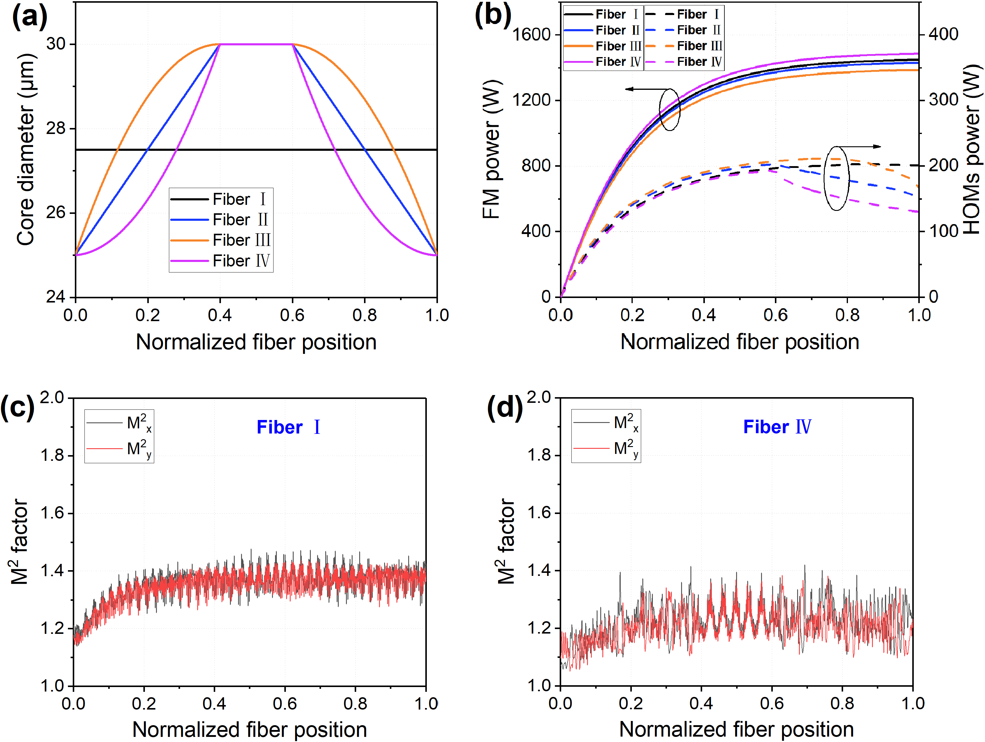
Figure 1 Simulation results of four types of fiber: (a) the core dimeter distribution, (b) FM power and HOM power (solid line, FM power distribution in fiber; dotted line, HOMs power distribution in fiber), (c) M 2 factor evolution of Fiber I and (d) M 2 factor evolution of Fiber IV.
Taking the structure of the CCTC fiber into account, a numerical model of the co-pumped fiber amplifier is established based on rate equations and coupled-mode theory. The central wavelength was 1080 nm. The pump and the signal powers were set to 2 kW and 10 W, respectively. According to the fiber parameters we have assumed above, we defined the injected signal power as that fundamental mode (FM) power nine-fold higher than the HOM power, where the input signal power of LP01, LP11, LP21 and LP02 modes was, respectively, 9 W, 0.4 W, 0.4 W and 0.2 W. The power evolution and mode coupling were simulated in the fiber amplifier. The power distributions of the FM and HOMs were calculated, as shown in Figure 1(b). From the simulation results, the HOMs power of these CCTC fibers first increases along the fiber length, and then decreases when the core diameter gradually decreases from the large core region to the small core region. This is due to the variation of the core diameter causing some HOMs to leak into the inner cladding and gradually vanish. The interference modes could also lead to the decrease of HOMs power in the CCTC fiber. According to the simulation results, Fiber IV has a better HOMs suppression along the fiber position, which is due to the smaller HOMs gain caused by the relatively smaller effective overlapping doping area and to the stronger HOMs leakage caused by the relatively steeper core diameter change trend in the region where the core diameter gradually decreases[Reference Shi, Wang, Zhou, Xu and Lu31]. In addition, the M 2 factor evolutions were also calculated, as shown in Figures 1(c) and 1(d). It was found that, compared with a conventional uniform fiber, the CCTC fiber can effectively maintain good beam quality along the fiber length during the power scaling.
To fabricate the CCTC YDF, an Yb/Al/Ce co-doped fiber preform was first produced using conventional MCVD combined with solution doping technology. The refractive index profiles of the fiber preform (plotted in Figure 2(a)) were measured at different positions along the preform using P104 (Photon Kinetics). It was shown that the refractive index distributions of the two interfaces are almost consistent and exhibit an excellent uniformity along the longitudinal position of the preform. The refractive index difference (Δn) between the core and cladding is 1.45 × 10⁻³, and the corresponding core numerical aperture (NA) is ~0.065.

Figure 2 (a) Refractive index profile at different positions along the length of the preform and (b) the core diameter distribution of the fabricated CCTC fiber.
During the next step, the preform was post-processed before the fiber drawing; a schematic diagram of post-processed preparation is shown in Figure 3. Both ends of the preform are fixed and stretched to form several cones in the longitudinal direction while being heated at certain points using a H2–O2 flame (Figure 3(a)). The stretched preform was ground into an octagon shape with a uniform outer diameter (Figure 3(b)). Finally, the ground preform was drawn into a fiber with a cladding diameter of 400 μm and coated with a low-index polymer coating. The CCTC YDF can be selected from the two adjacent conical regions along the obtained fiber (Figure 3(c)). The tapered ratio and the lengths of the different parts can be controlled during the tapering process of the preform. For the first CCTC fiber reported herein, the core shape was adopted to follow a parabolic function according to the simulation results.

Figure 3 Schematic diagram of the post-processed preparation.
The core diameter distribution along the axial direction of the CCTC fiber from the preform is shown in Figure 2(b). The CCTC fiber can be divided into three regions along the length of the fiber, with two gradually varying small regions at both ends and a large region in the middle. Region II is the large core region with a core/cladding diameter of 31/400 μm and length of approximately 4.8 m. Regions I and III are asymmetric conical regions: the core diameter of region I gradually transitions from 24.1 to 31.0 μm, and the core diameter of region III gradually transitions from 23.4 to 31.0 μm. The total length of this fiber is ~25 m, and the lengths of regions I and III are both 10.1 m. The average absorption coefficient was measured as ~1.54 dB/m at 976 nm. The equivalent core diameter of the fiber can be defined as follows[Reference Shi, Wang, Zhou, Xu and Lu31]:
 $${D}_{\mathrm{eff}}^{\mathrm{CCTC}}=\frac{\int_{z=0}^LD(z)\mathrm{d}z}{L},$$
where D(z) is the diameter of the CCTC fiber along the z-direction and L is the length of the fiber. Here, the calculated equivalent core diameter of the CCTC fiber is ~27.3 μm.
3 Application in high-power fiber laser
3.1 Experiment setup
To evaluate the laser performance of the fiber, a CW all-fiber oscillator was established based on the CCTC YDF. As shown in Figure 4, the fiber oscillator was constructed as a bidirectional pumping configuration. A series of high-brightness 976-nm wave-band LD modules (maximum power of ~900 W for each) were employed as pump sources, which were injected into the gain fiber through forward and backward (6 + 1) × 1 pump/signal combiners. The core/inner-cladding diameters of the input and output signal fibers are 25/400 and 25/250 μm, respectively. The core/cladding diameters of the pump ports are 220/242 μm, which is identical to the pigtail fibers of the LD modules. A pair of fiber Bragg gratings (FBGs) was utilized as the resonant cavity mirror. Both the high-reflection FBG (HR-FBG) and the output coupler FBG (OC-FBG) were inscribed in the 25/400 μm passive fiber. The reflectivity of the HR-FBG and OC-FBG was 99.8% and 10.5% at a central wavelength of ~1080 nm, respectively. The 3-dB bandwidths of the HR-FBG and OC-FBG are 3.07 nm and 0.97 nm, respectively. The gain fiber used in the fiber oscillator is a homemade CCTC YDF, which is coiled in a racetrack groove of a water-cooled plate with a bending diameter of 12–17 cm. A schematic diagram of the longitudinal structure of the CCTC fiber is shown in Figure 3(c). To deliver the signal laser, a ~3-m passive fiber with a core/inner-cladding diameter of 25/400 μm was spliced to the output port of the OC-FBG. The unabsorbed cladding light is removed by applying a cladding light stripper (CLS) to the passive fiber. A commercial quartz block head (QBH) with a pigtailed passive fiber was applied to avoid probable harmful feedbacks. All components of the fiber oscillator systems are cooled on the heat-sink plate to maintain efficient thermal management.

Figure 4 Experimental setup of an all-fiber laser oscillator system. BQA, beam quality analyzer (Beam Squared, Ophir); CO, collimator; DM, dichroic mirror; HR, high reflection; OSA, optical spectrum analyzer (Yokogawa, 600–1700 nm); PD, photodetector (Thorlabs, 150 MHz, 700–1800 nm); PM, power meter.
The laser performance of the CCTC YDF-based fiber oscillator, such as the output power, optical spectrum, beam quality and time-domain signals of the laser, was characterized during power scaling. The output spectra were monitored using an optical spectrum analyzer (OSA), and the temporal signals were measured using an InGaAs photodetector (PD), which is located at the center of the collimated light. The beam quality and beam profile of the output laser were measured using a beam quality analyzer (BQA).
3.2 Results and discussion
In the experiment, the backward and forward pumps were loaded successively in the laser system, and the relevant experimental results are as shown below. The measured output power and the corresponding optical-to-optical efficiency versus the pump power are shown in Figure 5(a). The output power exhibits a linear increase with the injected pump power, and the maximum output power reaches 3.42 kW with an optical-to-optical efficiency of ~55.2%. The optical-to-optical efficiency of this fiber oscillator is relatively lower than that of traditional uniform fiber oscillators[Reference Yang, Zhang, Shi, Wang, Zhou, Xu, Chen, Liu and Lu3, Reference Shima, Ikoma, Uchiyama, Takubo, Kashiwagi and Tanaka4]. The relatively lower optical-to-optical efficiency can be mainly attributed to the following two aspects. One is the mode field mismatch between the YDF and the pump combiner. The YDF has a core diameter of ~24 μm at both ends, whereas the output signal fiber of the combiner is 25 μm, which causes a part of the signal light to leak into the cladding and be stripped by the CLS, especially in the fiber oscillator structure. In addition, the core region varying from a large core size to a small core size inevitably reduces the optical efficiency, because a certain proportion of HOMs experience a higher bending loss owing to fiber coiling and thus leak into the cladding. The output spectra of the fiber oscillator were measured at five different powers and are plotted in Figure 5(b). Sufficient pump absorption and the employment of a CLS ensure that a clear signal is exhibited at ~1080 nm without a residual pump light. The spectral bandwidth of the signal laser broadens to ~5.58 nm at the maximum output power, which is mainly attributed to the nonlinear effects (such as self-phase modulation) in optical fibers. In addition, there is no obvious sign of Raman Stokes light observed at the maximum output power, indicating that this fiber oscillator has an excellent SRS suppression capability.

Figure 5 (a) Output power and corresponding optical-to-optical efficiency of the laser. The blue and green regions represent the backward and forward pump schemes, respectively. (b) Output spectrum measured at different output powers, showing an SRS suppression ratio of >35 dB at the maximum power.
The temporal features of a laser are often used to evaluate the laser’s stability and the occurrence of the TMI effect[Reference Otto, Stutzki, Jansen, Eidam, Jauregui, Limpert and Tünnermann32]. The measured PD signals and their corresponding Fourier transform spectra are plotted in Figure 6. When the output power increases from 3022 to 3128 W, power fluctuations and frequency peaks are clearly presented on the time traces and their corresponding Fourier transform spectra, respectively. This means that the TMI effect occurs in the laser system. Furthermore, when the output power is further scaled to 3.42 kW, the temporal fluctuation becomes more violent and the Fourier transform frequency components broaden remarkably in the Fourier spectra, indicating that the laser operates from a transition state into a chaotic state. The calculated standard deviation (STD) of the temporal signal (plotted in Figure 6(c)) also indicates the onset of the TMI, and the TMI threshold of the laser is ~3.12 kW.

Figure 6 (a) The normalized temporal signal at different output powers, (b) its corresponding Fourier transform spectra and (c) the STD of the temporal signals at different output powers.
The beam quality (M 2 factor) of the output laser is also measured and is shown in Figure 7(a) as a function of the output power. The measured M 2 factor is approximately 1.6–1.7 in both the x-axis and the y-axis before the occurrence of the TMI effect. The relatively poor beam quality can be mainly attributed to two reasons. First, the minimum V value at the output end of this CCTC fiber was calculated to be ~4.54, which could support several modes (LP01, LP11, LP21 and LP02) propagating in the fiber. Although fiber coiling was adopted as a mode-filtering technique in the experiment, the bending loss was not enough to remove all the HOMs and obtain near single-mode beam quality. In addition, imperfect matching between the CCTC fiber and the output signal fiber of the combiners inevitably induces the excitation of the HOMs, which will deteriorate the beam quality. With the output power increasing to 3.42 kW, the M 2 factor deteriorates to 1.88, which is a direct sign of the onset of the TMI effect[Reference Eidam, Wirth, Jauregui, Stutzki, Jansen, Otto, Schmidt, Schreiber, Limpert and Tünnermann9]. At an output power of 3022 W, the measured M 2 factor and the beam profile at the waist are as shown in Figure 7(b). It can be seen from the inset of Figure 7(b) that the beam spot was well maintained and there was no obvious mode distortion at this power level. Compared with the active tapered all-fiber laser oscillator in Ref. [Reference Yang, Zhang, Shi, Wang, Pan, Wang, Zhou and Xu29], which shares a close equivalent core diameter of ~25 μm, the fiber oscillator based on the CCTC fiber (equivalent core diameter of 27.3 μm) has a higher output power and TMI threshold under our experimental conditions.

Figure 7 (a) Measured beam quality evolution during the power scaling and (b) M 2 factor and beam profile at 3022 W.
From the above experimental results, the CCTC YDF has shown a significant potential to achieve a high-power fiber laser oscillator with a near-diffraction-limited beam quality, although the TMI effect was observed at an output power of ~3.12 kW. It is important to note that the CCTC fiber has a constant cladding diameter and varying core diameter. The constant cladding can make the uniformity and concentricity of the fiber coating much easier to control in the fabrication process. Compared with a traditional tapered fiber (in which the core and cladding vary simultaneously along the fiber)[Reference Yang, Zhang, Shi, Wang, Pan, Wang, Zhou and Xu29, Reference Ye, Xi, Shi, Yang, Wang, Zhang, Zhou and Xu30], the constant cladding diameter of the CCTC fiber means a varying core–cladding ratio, which has a smoother thermal load profile along the fiber. In addition, the large core section provides a large mode area to suppress the SRS effect. The specially designed small core section can be planned to support a single-mode operation and thus enhance the TMI threshold. By further optimizing the CCTC fiber structure, such as the core diameter distribution and transverse refractive index distribution, combined with confined-doped technology and ultra-low NA technology, in the future it is expected to achieve a higher output power without any sign of SRS and TMI effects.
4 Conclusion
In this paper, a novel long tapered YDF, which we call a CCTC fiber, was proposed and successfully fabricated in the lab using the MCVD method. Unlike all previously reported tapered fibers, the CCTC fiber consists of uniform cladding (diameter of ~400 μm) and a tapered core (diameter of ~24 μm at both ends and ~31 μm in the middle). The laser performance of this fiber has also been investigated in an LD pumped all-fiber oscillator, and over 3 kW of output power was achieved with an optical-to-optical efficiency of ~55.2%. The output power was scaled to a maximum value of 3.42 kW, where the beam quality (M 2 factor) degrades from 1.60 to 1.88. A better beam quality and further power scaling are promising for optimizing the fiber parameters. Because CCTC fibers with complex core structures can be produced from the MCVD method and fiber-drawing towers, they have significant potential for suppressing the nonlinear effects (such as SRS and stimulated Brillouin scattering ) and TMI effects in both CW and pulsed fiber lasers.
Acknowledgments
This work was partly supported by the National Natural Science Foundation of China (Nos. 61735007 and 61705266). The authors wish to thank Kun Zhang, Xiaoyong Xu, Tao Song, Chuanchuan Zhang, Siliu Liu, Lingfa Zeng, Yinchao Wan and Zhejian Hong for their assistance during the experiment. The authors Yun Ye and Xianfeng Lin contributed equally to this work.


 Open access