


Impact Statement
Droplet microfluidics has become a versatile technology with a multitude of applications. However, adding/withdrawing liquid into/from droplets with femtolitre volumes remains a challenge. The process reported here offers a solution to the liquid sampling problem and is controllable via the applied electric field. It could prove helpful in various applications where droplets are used as tiny reaction spaces or when the goal is to tailor the size of individual droplets.
1. Introduction
Droplets with diameters of the order of 1 μm or below are of interest for a plethora of applications. One application with rapidly growing perspectives is to use droplets or vesicles as biochemical reaction spaces, mimicking the processes inside biological cells or unicellular organisms (Reference Beneyton, Krafft, Bednarz, Kleineberg, Woelfer, Ivanov and BaretBeneyton et al., 2018; Reference dos Santos, Belluati, Necula, Scherrer, Meyer, Wehr and Meierdos Santos et al., 2020; Reference Fanalista, Birnie, Maan, Burla, Charles, Pawlik and DekkerFanalista et al., 2019; Reference Gach, Iwai, Kim, Hillson and SinghGach, Iwai, Kim, Hillson, & Singh, 2017; Reference Göpfrich, Platzman and SpatzGöpfrich, Platzman, & Spatz, 2018; Reference Haller, Göpfrich, Schröter, Janiesch, Platzman and SpatzHaller et al., 2018; Reference Shojaeian, Lehr, Göringer and HardtShojaeian, Lehr, Göringer, & Hardt, 2019; Reference Van Nies, Westerlaken, Blanken, Salas, Mencía and DanelonVan Nies et al., 2018; Reference Wang, Du, Wang, Mu and HanWang, Du, Wang, Mu, & Han, 2020; Reference Weiss, Frohnmayer, Benk, Haller, Janiesch, Heitkamp and SpatzWeiss et al., 2018). For such applications, it is of key importance to be able to manipulate/control the microscopic reaction spaces and to analyse/monitor the processes occurring inside. One essential building block of manipulation/control strategies is to add liquid or dissolved species to the reaction spaces or to withdraw them from there. Such operations were achieved via merging of a droplet with a liquid meniscus (Reference Song, Li, Munson, Ha and IsmagilovSong, Li, Munson, Ha, & Ismagilov, 2006), electrohydrodynamic injection/extraction (Reference Abate, Hung, Marya, Agresti and WeitzAbate, Hung, Marya, Agresti, & Weitz, 2010; Reference Zeng, Pan, Zhang, Lin and QinZeng, Pan, Zhang, Lin, & Qin, 2011) or diffusive transport between a droplet and a reservoir (Reference Shojaeian and HardtShojaeian & Hardt, 2020). Usually these operations become increasingly difficult the smaller the droplets get. With respect to analysing/monitoring processes inside tiny reaction compartments, cyclic voltammetry (Reference Batchelor-McAuley, Little, Sokolov, Katelhön, Zampardi and ComptonBatchelor-McAuley et al., 2016), plasmon-based electrochemical current monitoring of redox reactions (Reference Wang, Shan, Cui, Li, Wang and TaoWang et al., 2015) and monitoring of electrochemical reactions using ultramicroelectrodes (Reference Kim, Kim and BardKim, Kim, & Bard, 2015) were demonstrated, all inside single sub-femtolitre droplets. To produce reaction compartments, especially droplets, with diameters of the order of 1 μm or below, a number of methods are available. Classical methods such as ultrasonication (Reference Delmas, Piraux, Couffin, Texier, Vinet, Poulin and BibetteDelmas et al., 2011) or high-pressure homogenization (Reference HåkanssonHåkansson, 2019) usually yield quite broad droplet-size distributions. To better control the size of very small droplets, micro- or nanofluidic principles can be employed. Examples are membrane emulsification (Reference VladisavljevićVladisavljević, 2019), droplet production at submicron-scale T-junctions (Reference Toprakcioglu, Challa, Morse and KnowlesToprakcioglu, Challa, Morse, & Knowles, 2020), step emulsification (Reference Malloggi, Pannacci, Attia, Monti, Mary, Willaime and PoncetMalloggi et al., 2010) or tip streaming (Reference Anna and MayerAnna & Mayer, 2006; Reference Marín, Campo-Cortés and GordilloMarín, Campo-Cortés, & Gordillo, 2009; Reference Suryo and BasaranSuryo & Basaran, 2006).
In this work, we present a new method to manipulate droplets with volumes on the sub-femtolitre scale. The method is based on the partial coalescence of aqueous droplets with an aqueous reservoir under a direct-current (DC) electric field. Already in the 1960s it was discovered (Reference Allan and MasonAllan & Mason, 1961; Reference Charles and MasonCharles & Mason, 1960a, Reference Charles and Mason1960b) that, when an aqueous droplet is driven to an aqueous/oil interface by a DC electric field, it may rebound (non-coalescence) or re-emerge with a smaller size (partial coalescence). The non-coalescence mode was first rationalized in 2009 (Reference Ristenpart, Bird, Belmonte, Dollar and StoneRistenpart et al., 2009). Driven by the electric field, a Taylor cone (Reference Fernández de la MoraFernández de la Mora, 2007) forms at the droplet, after which a tiny liquid bridge is created between the droplet and the reservoir. For strong enough electric fields, the pressure inside the bridge exceeds the pressure in the droplet, thus driving liquid out of the bridge and causing pinch-off. As a result, the droplet does not coalesce with the reservoir, but bounces back, while at the same time its charge becomes inverted. In 2012, the partial coalescence mode between aqueous droplets and aqueous reservoirs was rationalized (Reference Hamlin, Creasey and RistenpartHamlin et al., 2012). For low enough values of the electric conductivity inside the drop, i.e. low enough values of the salt concentration, the droplet that re-emerges after a droplet comes into contact with the aqueous reservoir has a reduced volume.
Based on this preliminary work, we have demonstrated a device with which it is possible to transfer dissolved species between a reservoir and a droplet in a well-controlled manner (Reference Shojaeian and HardtShojaeian & Hardt, 2020). In this device, a droplet reciprocates between two aqueous reservoirs, driven by a DC electric field. Through the liquid bridge forming upon non-coalescence, the droplet exchanges dissolved species with the reservoirs. Specifically, this means that, when the droplet serves as a tiny reaction space, it can work as a semi-batch reactor, where reagents are introduced from one reservoir and reaction products are withdrawn from the other reservoir.
In this work we demonstrate another mode of manipulating droplets with volumes down to the sub-femtolitre range, which we believe is unprecedented for droplets in this size range. We show that, making use of partial coalescence, a part of the droplet liquid can be subtracted, even for droplets with diameters below 1 μm. This way, sampling of liquid from tiny reaction spaces is enabled. In context with synthetic cells that serve as a motivation for this work, this would mean that sampling operations become possible, analogous to the recently developed methods for extracting the contents of living cells (Reference ActisActis, 2018).
2. Experimental
The experiments were conducted in a microfluidic device, shown in Figure 1. The design of this device is the same as previously described (Reference Shojaeian and HardtShojaeian & Hardt, 2020). In brief, the key part of the chip is a cross-junction configuration. The shallow main channel is placed between two side channels of larger depth. The main channel contains the oil phase, and the side channels are filled with aqueous phase. The inlet sections of the side channels are connected to two ports of a power supply through needles, through which the DC electric field is applied. The width of the two side channels is different, so that the electric field lines become concentrated at the side channel of smaller width. This asymmetry enables droplet production through electric field pulses from the side channel of smaller width. Time lapse images showing the droplet production are shown in the supplementary materials are available at https://doi.org/10.1017/flo.2021.12.

Figure 1. Schematic of the microfluidic device, together with the high-voltage source and the imaging equipment. The blow-up shows the region of interest (indicated as a red rectangle) with a droplet exposed to the electric field applied through the side channels.
The microfluidic device was fabricated using the same protocol as previously described (Reference Shojaeian and HardtShojaeian & Hardt, 2020). Briefly, a SU-8 photoresist on a silicon wafer was microstructured using ultraviolet (UV) lithography, after which a standard soft lithography protocol was applied. The resulting microstructured polydimethylsiloxane (PDMS) substrate was then bonded to a glass slide covered with the thin PDMS layer, yielding a microchannel architecture exclusively with PDMS walls. More information on device fabrication can be found in the supplementary information.
The experimental procedures are very similar to those previously reported (Reference Shojaeian and HardtShojaeian & Hardt, 2020). Essentially, the main channel of the device is filled with silicone oil, the side channels with an aqueous salt solution. By applying a voltage pulse, a droplet is pinched off from the narrower side channel. The diameters of the droplets produced that way range between 2 and 16 μm. Subsequently, a DC electric field is applied between the side channels, upon which the droplet performs a reciprocating motion between the two liquid–liquid interfaces (in the following referred to as menisci). The droplet motion is imaged using an inverted microscope in brightfield mode (Nikon Eclipse Ti) and a high-speed camera (Redlake Motion Pro Series Y). More information on the experimental procedures can be found in the supplementary information. The working fluids are water at different salinities through addition of NaCl and 1000 cSt silicone oil AP (Sigma-Aldrich). A table with the most important properties of the liquids used can be found in the supplementary information.
3. Results and Discussion
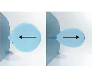
Different modes of droplet manipulation are possible with our microfluidic device. The standard mode is the reciprocating motion of droplets between the side channels, that can be used to introduce reagents into a droplet from one side channel and subtract reaction products from the opposing channel (Reference Shojaeian and HardtShojaeian & Hardt, 2020). By switching off the electric field, the droplet can be fixed at a position between the side channels, while the exchange with the reservoirs is suspended. Most notably, the partial coalescence mode that was previously observed for much larger droplets (Reference Hamlin, Creasey and RistenpartHamlin et al., 2012) also occurs for our micron-scale droplets. More specifically, for a salt concentration inside the droplet below a threshold value (in our case approx. 0.17 mM), a droplet may bounce back without volume loss for large enough values of the electric field strength, or it may experience a volume loss (partial coalescence) for smaller electric fields. This is demonstrated in Figure 2a. In this panel, and also in the other panels of this figure, the region of interest is rotated by 90° relative to Figure 1. Figure 2a shows snapshots from subsequent cycles of a droplet reciprocating between the two side channels, where the direction of motion is indicated by arrows. Since the electric field lines mainly extend between the two menisci, the field strength at the right meniscus is higher than that at the left meniscus. As a result, the conditions at the right meniscus are such that a droplet bounces off from that meniscus, while it undergoes partial coalescence at the left meniscus. This process is visible in the supplementary movies.

Figure 2. (a) Droplet reciprocating between the two menisci, undergoing partial coalescence at the left meniscus. The salt concentration is 0.17 mM and a voltage of 200 V was applied between the menisci. (b) Snapshots of consecutive cycles, showing the same droplet before getting in contact with the left meniscus. (c) A droplet with a diameter of approximately 800 nm that has been formed by partial coalescence and travels from left to right. The numbers indicate the time in milliseconds, and the red circle encloses the droplet. The parameters in panels b and c are the same as in panel a.
Partial coalescence gives the opportunity to reduce the diameter of droplets to the submicron scale. Figure 2b shows subsequent cycles from a reciprocating droplet motion shortly before undergoing partial coalescence with the left meniscus. The diameters of the droplets shown in the successive frames are 8.3, 6.9, 5.1, 3.4 and 1.6 μm. Our experiments do not give any indication that the cascade of droplet volume reduction comes to an end. However, due to the resolution limit of the optics, from a certain point on the droplets can no longer be imaged faithfully, but rather appear as a tiny grey patch. This is exemplified in Figure 2c. The figure shows a droplet experiencing a dramatic volume loss after partial coalescence with the left meniscus. The first frame shows the droplet before partial coalescence with the left meniscus. The daughter droplet, marked by the red circle, travels from left to right and has a diameter of approximately 800 nm. To estimate the size of such small droplets, a Gaussian function was fitted to the grey-scale values of the pixels around the position of a droplet. The full width at half-maximum was taken as an estimate for the droplet diameter. The smallest droplets that could be identified based on this method have a diameter of approximately 400 nm. However, the submicron diameters reported here should be taken with a grain of salt, since the Abbé resolution limit of the employed imaging system is approximately 600 nm. This means that the apparent droplet diameters are expected to be larger than the true diameters, since diffraction tends to broaden the grey-scale distributions. We speculate that the cascade of partial coalescence events continues for even smaller droplets, but these could not be detected using the available imaging system.
One key question is what determines the size of the daughter droplet for a given size of the parent droplet. When fixing the size of the parent droplet and the voltage between the side channels, there is still some fluctuation in the size of the daughter droplet. There are a few reports on the factors influencing the partial electrocoalescence of charged droplets with an oil–water interface, albeit for much larger droplets than considered in this work. (Reference Hamlin, Creasey and RistenpartHamlin et al. 2012) performed experiments from which they deduced that
 \begin{equation}\frac{a}{{{a_0}}} = K{\left( {\frac{{qE}}{{\gamma {a_0}}}} \right)^\alpha },\end{equation}
where q is the charge of the daughter droplet, E is the electric field strength, γ is the interfacial tension, a is the radius of the daughter droplet and a 0 that of the parent droplet. For the scaling exponent they obtained  $\alpha = 1/2$ and for the pre-factor $K = 0.85$. This is contrasted by the experiments reported by (Reference Anand, Juvekar and ThaokarAnand et al. 2020), who determined a scaling exponent $\alpha = 3/2$.
To study which factors influence the size of the daughter droplet, we have performed a number of experiments with varying parent droplet size, salt concentration and applied voltage. In previous studies only the charge of the daughter droplet was considered, but it is not a priori clear that the charge of the parent droplet should not play an equally important role in the partial coalescence process. Therefore, we have determined the droplet charge before and after partial coalescence. Details are given in the supplementary material. Figure 3 shows the effects of the electric field and salt concentration on the daughter droplet size for droplets with the initial sizes of 7 and 11 μm. The ratio of daughter and parent droplet sizes is plotted as a function of the square root of the electric Bond number  ${(qE/\gamma {a_0})^{1/2}}$. This parameter is largely analogous to the parameter used in (Reference Hamlin, Creasey and RistenpartHamlin et al. 2012), with the difference that, in our case, q is the arithmetic average of the daughter and parent droplet charges; E denotes the electric field, which, however, only enters the equations in form of the product qE. This product was determined based on the procedure described in the supplementary material. Figure 3 indicates a similarity relationship, i.e. to a good approximation the experimental data depend linearly on the square root of the electric Bond number. In total, the scaling relationship is given by
 \begin{equation}\frac{a}{{{a_0}}} = 0.978{\left( {\frac{{qE}}{{\gamma {a_0}}}} \right)^{1/2}}\theta \left[ {{{\left( {\frac{{qE}}{{\gamma {a_0}}}} \right)}^{1/2}} - 0.515} \right],\end{equation}
where θ is the Heaviside function and the numerical factors were determined based on a least-squares fit. A major difference to the results obtained for much larger droplets by Hamlin et al. lies in the fact that only above a critical value of the scaling parameter can partial coalescence occur. Translated to the charge of the droplet, this means that a minimum charge is required for partial coalescence, below that only full coalescence will occur. Equation (2) also allows us to check the results obtained for the size of droplets that are so small that they only appear as faint spots (cf. Figure 2c). From the velocity of these spots the droplet charge can be determined. The prediction of the scaling relationship is in good agreement with the Gaussian fits to the grey-scale distribution.
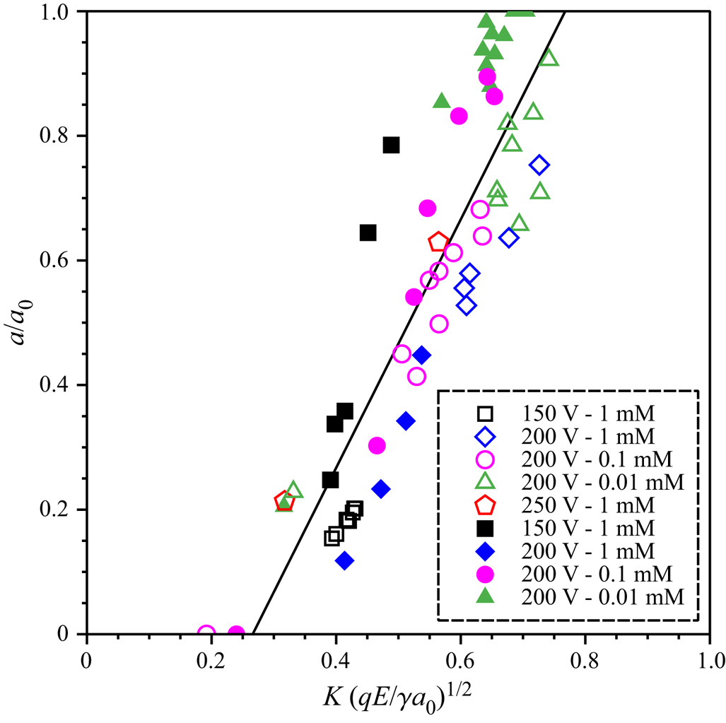
Figure 3. Dimensionless radius of the daughter droplet, plotted as a function of the square root of the electric Bond number. Experiments with different parent droplet diameters, salt concentrations and applied voltages were performed. The results for a parent droplet diameter of 7  $\mu$m are represented as open symbols, those for 11 $\mu$m as full symbols. The droplet charge could not be controlled in the experiments but was determined by measuring the droplet velocity.
Via equation (2), the charge of a droplet is a key factor determining its volume loss upon partial coalescence. To study how the droplet charge evolves when a droplet reciprocates between the two menisci, we observed droplets over a large number of cycles. Figure 4 shows results for two different droplets obtained for a salt concentration of 0.17 mM and a voltage of 250 V. Panel a shows the droplet diameter and panel b the ratio  $qE/a$, both as a function of cycle number. The quantities q and a are the droplet charge and radius measured right after partial coalescence with the meniscus at the larger side channel, respectively; $qE/a$ defines the scale of the electrostatic stress on the liquid–liquid interface, in the sense that dividing this ratio by a yields a characteristic value of the stress. It can be seen that the droplets perform a large number of cycles upon which their diameter reduces gradually. After a critical diameter is reached, a rapid volume loss is observed. This transition corresponds to a transition in $qE/a$, which remains approximately constant before the critical diameter is reached and suddenly decreases above the critical diameter. Since the electric field was constant in these experiments, this means that, up to the critical diameter, $q/a$ remains approximately constant. Note that the values of $qE/a$ are of the same order of magnitude as the interfacial tension between the two liquids (~35 mN m−1), which is an indication that the partial coalescence could be governed by a balance between interfacial tension and electrostatic forces. When the voltage is increased to 300 V, qualitatively the same behaviour is observed as in Figure 4a, with a slightly reduced critical diameter (see supplementary information). If the voltage is too low (for the experiments shown in Figure 4a, ~150 V), a critical diameter below which the droplet size rapidly decreases is not observed. The critical diameter is independent of the initial droplet size at the start of the reciprocating motion, where we consider initial diameters larger than the critical diameter. The gradual decrease in droplet diameter visible in Figure 4a can be utilized to consecutively withdraw minute samples from small droplets.

Figure 4. (a) Evolution of the diameter of two different droplets over a large number of cycles. The horizontal line indicates the approximate value of the critical diameter and serves as a guide to the eye. (b) Corresponding evolution of the parameter qE/a. The salt concentration was 0.17 mM and the voltage 250 V.
The discussion of the preceding paragraphs, especially the dependence on the electric Bond number  $qE/\gamma {a_0}$, gives some vague hints to the physics underlying the partial coalescence of these micron-sized drops. While we emphasize that the purpose of this manuscript is not to discuss the flow physics in any detail, we wish to briefly comment on the underlying mechanisms. The physics of partial coalescence of millimetre-sized droplets has been studied in some detail (see, for example, Reference Hamlin, Creasey and RistenpartHamlin et al., 2012; Reference Li, Wang, Vivacqua, Ghadiri, Wang, Zhang and WangLi et al., 2020, Reference Li, Dou, Yu, Huang, Zhang, Xu and Wang2021). Compared with that, the droplets considered here have a diameter that is approximately three orders of magnitude smaller, implying that the corresponding dimensionless groups differ vastly as well. This excludes transferring the insights from larger scales to the smaller scales considered here.
We are only aware of one study that discusses the partial coalescence of micron-sized droplets under an electric field (Reference Pillai, Berry, Harvie and DavidsonPillai et al., 2017). In this numerical study, equal properties of the droplet liquid and the oil phase were assumed, a marked difference to our studies where the oil had a viscosity more than three orders of magnitude higher than the droplet. Still, there are some similarities in the results. Roughly, in (Reference Pillai, Berry, Harvie and DavidsonPillai et al. 2017), the partial coalescence mechanism is described as a competition between electrostatic and capillary forces. When a droplet approaches the meniscus, it is already polarized by the electric field, where the part of the droplet that faces the meniscus (the “south pole”) carries charges of a sign opposite to that of the charges at the meniscus. After the droplet gets in touch with the meniscus, charge exchange happens, but most of the charges at the ‘north pole’ of the droplet remain there, inducing a force of the order of  $qE$ that pulls the droplet away from the meniscus. This force is counteracted by the capillary force $\gamma {a_0}$ that pushes the droplet towards the meniscus. It is that balance that explains the emergence of the electric Bond number $qE/\gamma {a_0}$. (Reference Pillai, Berry, Harvie and DavidsonPillai et al. 2017) and (Reference Hamlin, Creasey and RistenpartHamlin et al. 2012) agree as far as the relevance of this parameter is concerned, but they report different scaling exponents. Our scaling exponent agrees with that of (Reference Hamlin, Creasey and RistenpartHamlin et al. 2012), but an important difference to both papers is that in our case q is the average between daughter and parent droplet charge, whereas both works referred to define q as the daughter droplet charge. Our choice of the electric Bond number could hint to the fact that during the partial coalescence process charge is continuously transferred to the droplet, which makes a description only in terms of the daughter droplet charge questionable. Apart from that, more work is definitely needed to understand the physics of partial coalescence on such small scales. For example, what comes as a surprise considering the high oil viscosity is the fact that the viscosity does not enter Equation (2), at first sight suggesting that viscous forces do not play a role. Of course, the viscosity may be hidden in the numerical parameters appearing in this equation. Unfortunately, our attempts to study the influence of viscosity were unsuccessful, leaving this issue to be settled by future studies. The same type of silicone oil is also available with a viscosity of 100 cSt. It turned out that, with the lower viscosity silicone oil, upon application of an electric field, the menisci became unstable and the water phase protruded into the main channel. We speculate that surface-active contaminants are responsible for this failure mode.
4. Summary, Conclusions and Outlook
We demonstrated a scheme for manipulating droplets with volumes down to the sub-femtolitre range that is based on partial coalescence with a liquid reservoir under an electric field. Partial coalescence occurs when aqueous droplets with a not too high salt concentration reciprocate in an oil phase between two liquid–liquid menisci. The smallest droplets processed that way had a diameter of approximately 400 nm. The experimental data on the droplet diameters before and after partial coalescence can be collapsed to a single curve when expressing the diameter ratio as a function of the ratio between the electrostatic stress acting on a droplet and the interfacial tension. This is an indication that the physics of partial coalescence is governed by a balance between the electrostatic stress and interfacial tension. When letting droplets reciprocate between the two menisci over a large number of cycles, first the droplet volume reduces rather gradually until a critical diameter is reached, after which the droplets shrink rapidly.
The scheme allows withdrawing minute samples from small droplets and could prove helpful in various applications where droplets are used as tiny reaction spaces or when the goal is to tailor the size of individual droplets. The process can be controlled by the applied electric field. When the field is switched off, a droplet has no exchange with the reservoirs. The exchange can be initiated by switching on the electric field. For large values of the field strength, a droplet can diffusively exchange dissolved species with the reservoirs without experiencing any volume loss (Reference Shojaeian and HardtShojaeian & Hardt, 2020). For reduced field-strength values, this transitions into the partial coalescence mode described here. In this way, the electric field serves as a control parameter to control the interaction of tiny droplets with liquid reservoirs. On the fundamental side, there is a need of better understanding the physical mechanisms behind the partial coalescence of micron-sized droplets under electric fields. Also, it would be very interesting to explore the limits of the partial coalescence process. With the available experimental equipment, droplets with diameters below approximately 400 nm could no longer be detected, but it could well be that partial coalescence even occurs for nanodroplets.
Acknowledgements
We thank T. Meckel, TU Darmstadt, for helpful discussions on microscopy techniques, K.-D. Voss, TU Darmstadt, for his assistance in microfabrication, and S. Dehe, TU Darmstadt, for his assistance in composing the graphical abstract.
Competing Interests
The authors declare no conflicts of interest.
Author Contributions
Conceptualization: M.S.; S.H. Methodology: M.S; S.H. Data curation: M.S. Data visualisation: M.S. Writing original draft: S.H. All authors approved the final submitted draft.
Data Availability Statement
The research data related to this work are available at https://tudatalib.ulb.tu-darmstadt.de/handle/tudatalib/2847.
Ethical Standards
The research meets all ethical guidelines, including adherence to the legal requirements of the study country.
Supplementary Material and Movies
Supplementary material and movies are available at https://doi.org/10.1017/flo.2021.12.


 Open access