


1. Introduction
The interaction of ultra-intense short laser pulses with plasma has been proposed as a significant mechanism for high-energy particles in the last decades. In particular, energetic ion beams have a multitude of promising potential applications in many areas, such as proton radiography (Borghesi et al. Reference Borghesi, Mackinnon, Campbell, Hicks, Kar, Patel, Price, Romagnani, Schiavi and Willi2004), tumour therapy (Fourkal et al. Reference Fourkal, Shahine, Ding, Li, Tajima and Ma2002), materials characterization (Passoni, Fedeli & Mirani Reference Passoni, Fedeli and Mirani2019; Mirani et al. Reference Mirani, Maffini, Casamichiela, Pazzaglia, Formenti, Dellasega, Russo, Vavassori, Bortot and Huault2021; Boivin et al. Reference Boivin, Vallières, Fourmaux, Payeur and Antici2022) and fast ignition in inertial confinement fusion (Tabak et al. Reference Tabak, Hammer, Glinsky, Kruer, Wilks, Woodworth, Campbell, Perry and Mason1994), etc. Several mechanisms for laser-driven ion acceleration have been developed, including target normal sheath acceleration (TNSA) (Snavely et al. Reference Snavely, Key, Hatchett, Cowan, Roth, Phillips, Stoyer, Henry, Sangster and Singh2000; Wilks et al. Reference Wilks, Langdon, Cowan, Roth, Singh, Hatchett, Key, Pennington, MacKinnon and Snavely2001; Mora Reference Mora2003), radiation pressure acceleration (Robinson et al. Reference Robinson, Zepf, Kar, Evans and Bellei2008; Yan et al. Reference Yan, Lin, Sheng, Guo, Liu, Lu, Fang and Chen2008), collisionless shock acceleration (Xie et al. Reference Xie, Cao, Gong, Cheng, Liu, Zheng and He2019; Tochitsky et al. Reference Tochitsky, Pak, Fiuza, Haberberger, Lemos, Link, Froula and Joshi2020), magnetic vortex acceleration (Bulanov et al. Reference Bulanov, Bychenkov, Chvykov, Kalinchenko, Litzenberg, Matsuoka, Thomas, Willingale, Yanovsky and Krushelnick2010; Nakamura et al. Reference Nakamura, Bulanov, Esirkepov and Kando2010; Li et al. Reference Li, Chao, Xie, Liu, Zhou, Zhang, Yang, Liu, Cao and Zheng2022), etc. Among these, TNSA has been studied widely both in simulations and experiments (Maksimchuk et al. Reference Maksimchuk, Gu, Flippo, Umstadter and Bychenkov2000; Wagner et al. Reference Wagner, Deppert, Brabetz, Fiala, Kleinschmidt, Poth, Schanz, Tebartz, Zielbauer and Roth2016; Lv et al. Reference Lv, Zhao, Wan, Cai, Meng, Xie, Liu, Liu, Zhang and Zhang2019). In this scheme, the incident laser pulse irradiates the solid target and the electrons at the front surface are heated and accelerated. The hot electrons propagating forward can penetrate through the target, creating a charge-separation electric field in the vacuum space near the rear of the target. The electric field, several teravolts per metre, is strong enough to ionize the hydrogen atoms and accelerate the resulting protons, which are usually from water or hydrocarbon contaminants attached to the target surface (Chao et al. Reference Chao, Cao, Zheng, Liu and He2022).
In TNSA, the quality of accelerated protons is determined by hot electrons from the target, which depend on the intensity of the incident laser and the absorption of laser energy by the plasma. Compared with increasing the laser intensity, improving the laser-to-electron energy conversion efficiency is more likely for implementation for the sake of high-quality protons. An effective way to enhance the energy coupling efficiency from the laser to the electrons is using targets with a structured front surface. There has been a good deal of effort put into investigating the effect of structured targets on laser–plasma coupling, including double-layer targets (Yang et al. Reference Yang, Zhou, Huang, Ju, Jiang, Cai, Zhang, Wu, Qiao and Yu2018), cone targets (Honrubia, Morace & Murakami Reference Honrubia, Morace and Murakami2017), nanotube targets (Chatterjee et al. Reference Chatterjee, Singh, Ahmed, Robinson, Lad, Mondal, Narayanan, Srivastava, Koratkar and Pasley2012) and nano-structured targets (Zhao et al. Reference Zhao, Cao, Cao, Wang, Huang, Jiang, He, Wu, Zhu and Dong2010; Xie et al. Reference Xie, Cao, Chao, Jiang, Liu, Zheng and He2020; Blanco et al. Reference Blanco, Flores-Arias, Ruiz and Vranic2017), etc. Thus, a high-contrast laser is required to prevent the surface structures from being damaged or destroyed before the main laser pulse arrives (Calestani et al. Reference Calestani, Villani, Cristoforetti, Brandi, Koester, Labate and Gizzi2021).
For a flat solid foil target irradiated by the incident laser, the laser pulse is largely reflected at the plasma critical density. By contrast, a nanowire target which has a stack of thin plasma layers at subwavelength spacing grown on a thin metallic substrate (Cao et al. Reference Cao, Gu, Zhao, Cao, Huang, Zhou, He, Yu and Yu2010; Wang et al. Reference Wang, Cao, Zhao, Yu, Gu and He2012; Yu et al. Reference Yu, Zhou, Cao, Zhao, Cao, Shan, Liu, Jin, Li and Gu2012) is beneficial to generate more hot electrons. The complex geometry enables the laser pulse to interact for an extended distance with the inner volume of the target. As mentioned in previous studies (Feng et al. Reference Feng, Ji, Shen, Geng, Guo, Yu, Xu and Zhang2018), electrons within the nanowires will be pulled out by the laser field and accelerated by direct laser acceleration. Ultimately, these electrons, gaining considerable kinetic energy, will set up an enhanced sheath field for TNSA. For a laser pulse with Gaussian profile in the transverse direction, the sheath field in the target rear surface also appears as a Gaussian shape. The most energetic protons come from the axial position of the sheath field, so it is of prime importance to suppress the transverse diffusion of hot electrons. To achieve this goal, a strong magnetic field of more than 10 000 T has been applied in the longitudinal direction in some previous simulation works (Gong et al. Reference Gong, Cao, Pan, Xiao, Wu, Zheng, Liu and He2017; Kuri, Das & Patel Reference Kuri, Das and Patel2017), but it is still very challenging and not practical to reach such strength in experiments for now.
In this study, we proposed a novel tailored target referred to as a curved surface nanowire target (CSNT), which originates from a planar nanowire target (PNT) but surfaces of both the nanowires and the substrate are curved. For convenience, a schematic diagram is plotted in figure 1(c) to illustrate the features of two kinds of targets. The yellow part is the nanowire target, the grey part is the hydrogen layer and the light blue part donates the electron cloud. A large proportion of hot electrons at $\lambda _{0}/2$ (λ0 is the laser wavelength) intervals are pulled out from the nanowires by the periodic laser electric field and accelerated forward, and then, they transport to the rear surface of the target. An electron cloud is formed and a strong charge-separation field is also established there to accelerate the protons from the hydrogen layer. The design of the CSNT aims to reduce the reflection and enhance the absorption of the incident laser, and meanwhile plays a better role in constraining the transverse motion of hot electrons. Given the technological advances in the fabrication of nano-structured targets, a possible way to realize such a kind of target is $3$
 D printing using the two-photon polymerization ($2$
 PP) additive manufacturing technique (Bailly-Grandvaux et al. Reference Bailly-Grandvaux, Kawahito, McGuffey, Strehlow, Edghill, Wei, Alexander, Haid, Brabetz and Bagnoud2020). Here, a series of two-dimensional (2-D) particle-in-cell (PIC) simulations are carried out to compare the CSNT and the PNT.
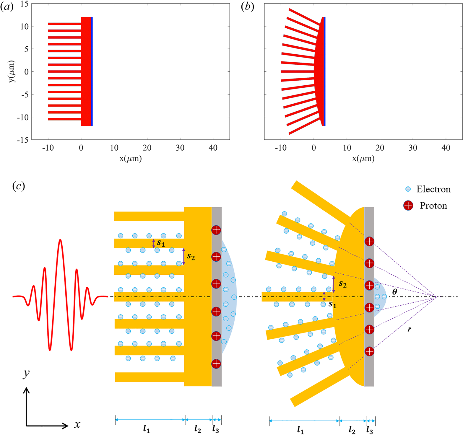
Figure 1. Target configurations of the PNT (a) and the CSNT (b) in the simulations. Both targets consist of nanowires and substrate of ${\rm Au}^{10+}$ (red), and a thin hydrogen foil (blue) adheres to the target rear. (c) Schematics of the planar nanowire target (a) and the curved surface nanowire target (b).
This work is organized as follows. In § 2, the simulation set-up and target parameters are presented. In § 3, the enhancement of TNSA using the CSNT is shown in simulation results in detail. In addition, the robustness of the CSNT is examined by a simulation scan over the target parameters. The conclusions are summarized in § 4.
2. Simulation set-up
Our 2-D simulations use relativistic PIC code EPOCH (Arber et al. Reference Arber, Bennett, Brady, Lawrence-Douglas, Ramsay, Sircombe, Gillies, Evans, Schmitz and Bell2015). The simulation box is $x \times y=60\ \mathrm {\mu }{\rm m} \times 30\ \mathrm {\mu }{\rm m}$ , which is divided into $4000\times 3000$
 cells, and each cell is filled with $100$
 electrons, $10$
 gold ions and $100$
 hydrogen ions. The grid mesh spacing is enough to resolve the minimum characteristic scale of the problem. The time resolution is decided by the spatial resolution, according to the Courant-Friedrichs-Lewy (CFL) condition. The left boundary conditions of the fields are so-called simple laser, which allow electromagnetic (EM) waves to propagate with as little reflection as possible and particles are fully transmitted so this is a reasonable choice for the boundary at which the EM pulse enters the simulation box. The top, bottom and right conditions of fields and the boundaries of the particles are all open. A p-polarized laser pulse with a wavelength of $\lambda _0 = 0.8\ \mathrm {\mu }{\rm m}$
 and waist $w=8\ \mathrm {\mu }{\rm m}$
 is incident from the left boundary of the simulation domain. The laser pulse has a Gaussian spatial profile, and a flat-top temporal shape with a duration of $16\, T_{0}$
 , including a rising edge of $2\, T_{0}$
 and a descending edge of $2\, T_{0}$
 , where $T_{0}$
 is the laser period. The peak intensity is $I_{0}\sim 1.37\times 10^{20}\ {\rm W}\ {\rm cm}^{-2}$
 , corresponding to the normalized vector potential $a_{0} = 8$
 .
.
The regular PNT consists of three parts, which appear as a comb structure, shown in figure 1(a). The first part is nanowires made of Au with diameters $s_{1} = 0.5\ \mathrm {\mu }{\rm m}$ , vacuum spacing $s_{2} = 1\ \mathrm {\mu }{\rm m}$
 and length $l_{1} = 10\ \mathrm {\mu }{\rm m}$
 . They are assumed to be pre-ionized ${\rm Au}^{10+}$
 with density of $n_{i} = 5n_{c}$
 and a corresponding electron density of $n_{e} = 50\, n_{c}$
 , where $n_{c} = m_{e} \omega _{0}^{2} \epsilon _{0}/e^{2}$
 is the critical density, $m_{e}$
 is the electron mass, $\epsilon _{0}$
 is the vacuum permittivity and $e$
 is the unit charge. The second part is a substrate of the same materials with a thickness of $l_{2} = 3\ \mathrm {\mu }{\rm m}$
 . The nanowires and the substrate are placed in the region $-10\ \mathrm {\mu }{\rm m} < x < 3 \mathrm {\mu }{\rm m}$
 and $-12\ \mathrm {\mu }{\rm m} < y < 12\ \mathrm {\mu }{\rm m}$
 . The third part is a $0.5\ \mathrm {\mu }{\rm m}$
 thick ($l_{3} = 0.5\ \mathrm {\mu }{\rm m}$
 ) and $12\ \mathrm {\mu }{\rm m}$
 wide hydrogen plasma layer attached to the rear of the substrate, with $n_{H} = n_{e} = 10\, n_{c}$
 , in the region $3\ \mathrm {\mu }{\rm m} < x < 3.5\ \mathrm {\mu }{\rm m}$
 and $-12\ \mathrm {\mu }{\rm m} < y < 12\ \mathrm {\mu }{\rm m}$
 .
.
The CSNT resembles the PNT, except that the front surface of the substrate is curved and the nanowire arrays extend in a radial pattern. That is, the profiles of the surface of the nanowire and the substrate appear to be in concentric circles. The vacuum spacing of nanowires in CSNT is approximately $s_{2} = 1\ \mathrm {\mu }{\rm m}$ , as seen in figure 1(b). Moreover, the diameter of the nanowire, the length, density and location are the same as the PNT. In our simulations, the parameter scope of the radius of curvature of the substrate $r$
 is from $30\ \mathrm {\mu }{\rm m}$
 to $500\ \mathrm {\mu }{\rm m}$
 . The centre of the circle of curvature is located on the $x$
 -axis and the horizontal distance from the $y$
 -axis is equal to the radius of curvature $r$
 . In order to ensure comparability with the PNT, the minimum value of $r$
 is set as $30\ \mathrm {\mu }{\rm m}$
 so that the thickness of the substrate and the number of nanowires in two cases can be nearly equivalent. Here, the central angle, as a more intuitive variable, is governed by the vacuum spacing of nanowires in the CSNT and the radius of curvature of the substrate: $\theta =(s_{1}+s_{2})/{r}$
 . The almost same central angle is set between each of two nanowires.
3. Simulation results and discussion
3.1. Laser absorption and hot electron generation
In the typical TNSA regime, a flat solid target is irradiated by an intense laser pulse to generate hot electrons which are heated by vacuum heating and the $J\times B$ acceleration. Hot electrons set up a sheath electric field at the surface of the target for proton acceleration. However, the laser pulse can only travel several skin depths into the target, so that a great amount of energy is reflected. Figure 2 shows the longitudinal Poynting flux $S_{x}$
 normalized by $(m_{e}\omega _{0}c/e)^{2}$
 at $t=20\, T_{0}$
 . Both incident and reflected components of the Poynting flux can be observed at this moment. Compared with the PNT, the reflected component is weaker in the CSNT. The reflectivity can be estimated by integrating the Poynting flux $S_{-}$
 propagating in the negative direction at the left boundary, expressed as

where $w_{0}$ is the total energy of the incident laser pulse. The value of $R$
 determines the energy that flows into the target, which is closely linked to the temperature of the hot electrons. The reflectivity in the PNT is $22\,\%$
 , while in the CSNT it is only $17\,\%$
 . This result indicates that, in the CSNT, more energy is transferred to the electrons within the nanowires.

Figure 2. The longitudinal Poynting flux $S_{x}$ normalized by $(m_{e}\omega _{0}c/e)^{2}$
 at $t=20\, T_{0}$
 for the PNT (a) and the CSNT (b).
The energy density distributions of hot electrons in two cases at $t=30\, T_{0}$ are presented in figures 3(a) and 3(b), which are normalized by ${n_{c}m_{e}c^{2}}$
 . It is clear that the energy density of hot electrons in the CSNT is apparently higher than that in the PNT. A large number of high energy density electrons are pulled out from the nanowires by the periodic laser electric field and accelerated forward, and eventually they are transported to the centre region of the target rear surface. The convergence caused by the geometry of the CSNT counteracts part of the lateral diffusion, and thus the distribution of hot electrons is more concentrated at the rear of the target in the CSNT. To further certify the convergence effect of the CSNT, the profiles of energy density along the $x$
 -axis are plotted in figure 3(c) to reveal the comparison of the two cases, which profiles are averaged over the target rear surface region. The transverse motion of hot electrons is effectively confined and the energy density of the electrons is naturally increased in the CSNT. Furthermore, the energy spectra of electrons in both cases are exhibited in figure 3(d). It can be seen that, due to more effective heating, the number of electrons with high energy in the CSNT is higher than that in the PNT. Counting all electrons moving forward, the maximum energy of hot electrons in the CSNT is over $47$
 MeV, compared with a maximum energy of only $30$
 MeV in the PNT. The temperature of the hot electrons $T_{h}$
 has increased from $3.8$
 to $5.3$
 MeV, which can be obtained by fitting the spectra with a Maxwellian distribution, as given by the dashed line in 3(d). As discussed above, due to the higher energy conversion efficiency from the laser to electrons, the temperature of the electrons in the CSNT increases as expected.

Figure 3. Energy density of hot electrons in the PNT (a) and in the CSNT (b) at $t=30\, T_{0}$ . (c) Averaged energy density of hot electrons along the $y$
 direction within the region $-15\ \mathrm {\mu }{\rm m} < x < 3\ \mathrm {\mu }{\rm m}$
 . (d) The energy spectra of hot electrons at $t=30\, T_{0}$
 .
.
3.2. Sheath filed and proton acceleration
As hot electrons originating from the nanowires propagate through the target rear, a longitudinal sheath field is established, and it can be estimated as (Arefiev, Toncian & Fiksel Reference Arefiev, Toncian and Fiksel2016)
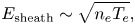
where $n_{e}$ , $T_{e}$
 are the density of hot electrons and characteristic kinetic energy, respectively. The characteristic scale of the sheath is the Debye length $\lambda _{D}=\sqrt {\epsilon _{0} T_{e}/ n_{e} e^{2}}$
 . According to (3.2), the sheath field is proportional to the square root of the product of the number density and temperature of hot electrons. The strong sheath field is determined by the ability of the laser pulse to generate copious energetic electrons. Figure 4 shows the sheath field near the rear of the target of two cases at $t=30T_{0}$
 . The moment is chosen when the longitudinal electric field reaches its peak value in our simulations. As performed in figures 4(a) and 4(b), it is found that the longitudinal electric field in the CSNT is more localized in the transverse direction, which is closer to the axis $y=0$
 . On the other hand, the electric field in the CSNT occupies a larger area compared with that in the PNT, that is, the characteristic scale of the sheath electric field in the CSNT is larger than that in the PNT. From figure 4(c), one can see that the amplitude of electric field along the $x$
 -axis at $y=0$
 in the CSNT exceeds that in the PNT. It is obvious that the amplification of the sheath electric field in the CSNT is more than $20\,\%$
 compared with the PNT.
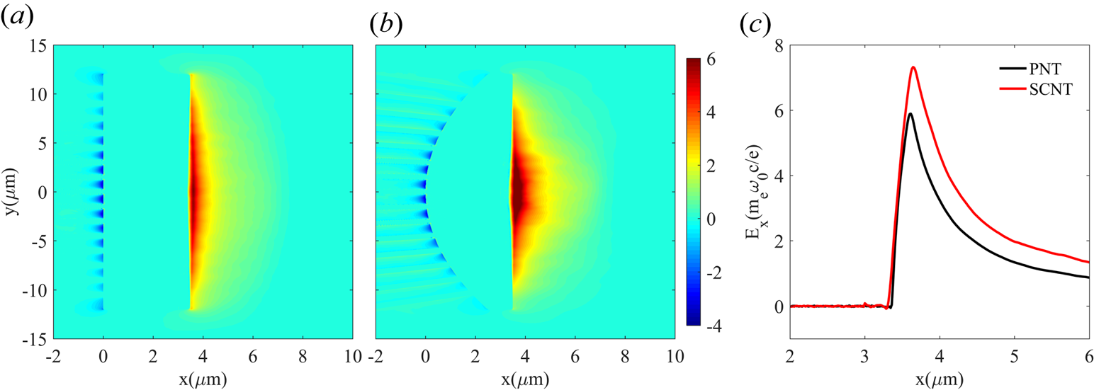
Figure 4. Longitudinal electric fields $E_{x}$ at $t=30T_{0}$
 near the target rear surface for (a) the PNT and (b) the CSNT. (c) The corresponding slices of $E_{x}$
 along the $x$
 -axis, averaged near the region $y=0$
 . Here, $E_{x}$
 is normalized by $m_{e}\omega _{0}c/e$
 .
.
As shown in figure 5, the energy spectra of protons at the end of the simulation exhibit a similar Boltzmann distribution, which is a typical spectral shape of TNSA. The proton cutoff energy in the CSNT is evidently higher than that in the PNT, which is in accordance with the snapshots of the sheath field of two kinds of target. Using this tailored target design, the cutoff energy increase from $50$ to $73$
 MeV. We count these energetic protons and find that the energy conversion efficiency from laser to forward protons with energy above $5$
 MeV is $11.6\,\%$
 in the PNT and $14.2\,\%$
 in the CSNT. The simulation results demonstrated that the CSNT has better performance than the PNT in generating high-energy protons.
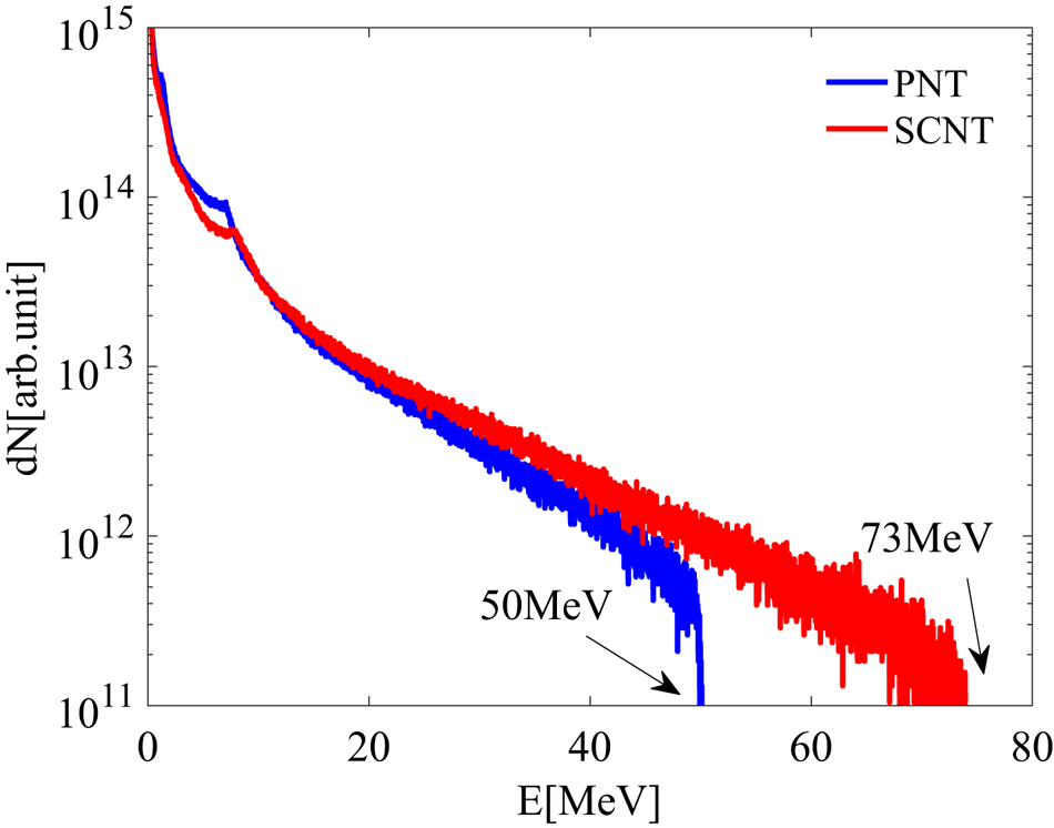
Figure 5. The proton energy spectra in the PNT (blue) and in the CSNT (red) at the end of simulation.
To study the robustness of the CSNT, several central angles, corresponding to different radii of curvature of the curved surface nanowire target, are adopted in different simulation cases. The radii of curvature of the curved surface nanowire target vary from $30$ to $500 \mathrm {\mu }{\rm m}$
 , and the corresponding central angle $\theta =0.05$
 , $0.037$
 , $0.03$
 , $0.021$
 , $0.015$
 , $0.01$
 and $0.003$
 radians. As the radius of curvature of the curved surface nanowire increases, the central angle of the nanowires decreases. Finally, the matching relation of the central angle and the radius of curvature can be extrapolated to the limiting case $\theta =0$
 , namely, the case of the planar nanowire target. The cutoff energy of protons and the conversion efficiency with different central angles are shown in figures 6(a) and 6(b). For the CSNT with different radii of curvature of nanowires, both the cutoff energy and the conversion efficiency nearly linearly increase with the central angle. Besides, the cutoff energy of protons and the conversion efficiency in the CSNT are higher than those in the PNT. It is clear that this target design can significantly increase the cutoff energy and the number of accelerated protons.

Figure 6. The dependence of (a) cutoff energy and (b) conversion efficiency of protons on different central angles.
4. Conclusions
In summary, 2-D PIC simulations are performed to study the improvement of a novel nanowire target on laser-driven proton acceleration in TNSA. By using a curved nanowire target, the electron energy density is significantly improved compared with that in a planar nanowire target, and thereby the sheath electric field is enhanced. A series of simulations with varied central angles of the nanowires is employed to reveal the effectiveness of CSNT. With the increase in the central angle, the cutoff energy of protons and conversion efficiency clearly increase. Our simulation results show that the cutoff energy and the number of accelerated protons in the CSNT are superior to those in the PNT. This enhancement can be attributed to suppressed transverse diffusion of hot electrons and enhanced absorption of laser energy. This scheme could be helpful in generating high-quality proton beams in experiments without requiring higher laser intensity.
Acknowledgements
This work was supported by the National Natural Science Foundation of China (grant nos. 11875091 and 11975059), and the Science and Technology on Plasma Physics Laboratory at CAEP (grant no. JCKYS2019212012).
Editor Victor Malka thanks the referees for their advice in evaluating this article.
Declaration of interests
The authors report no conflict of interest.


