


1. Introduction
Blood test results are an important reference for doctors to make a clinical diagnosis, where venipuncture blood collection (VPBC) is a crucial step in blood tests. Relevant data show that nearly 3.5 million venipunctures are performed worldwide every day [Reference Mccann, Einarsdóttir, Van Waeleghem, Murphy and Sedgewick1, Reference Walsh2]. Traditional venipuncture is manually conducted by medical staff, and the success rate depends on both their proficiency and the physical condition of patients. The success rate of venipuncture in infants, the elderly, and obese patients with difficult venous access is significantly lower than that in normal adults [Reference Armin, John, H.Kevin, Leah and Tofy3]. Difficult or failed venipuncture costs the United States healthcare system $4.7 billion annually [Reference Boer, Steinbuch, Neerken and Kharin4].
Robotics has developed rapidly in the past three decades, the application of which in the medical field has significantly influenced the way of diagnosis and treatment [Reference Liu, Harewood, Chen and Chen5–Reference Li, Milutinovic and Rosen7]. Compared with human operators, medical robots, with high accuracy and good stability, can work efficiently for a long time. To solve the problem of traditional venipuncture, robotic technology, venous imaging, and force feedback technology are widely used in VPBC. Many scientific research institutions have researched venipuncture technology and developed VPBC robots. In 2010, the VascuLogic Company developed a blood collection robot Veebot [Reference Perry8], which uses monocular near-infrared and ultrasound imaging technology to guide the end of an industrial manipulator with a puncture mechanism for VPBC, with a success rate of 83%. Alvin Chen et al. from the Rogers State University developed three generations of venipuncture robots [Reference Chen, Nikitczuk, Nikitczuk, Maguire and Yarmush9–Reference Chen, Balter, Maguire and Yarmush11]. In 2017, the third-generation 9-degree-of-freedom (DOF) venipuncture robot was proposed [Reference Balter, Chen, Maguire and Yarmush12]. The binocular near-infrared imaging, ultrasound imaging, and puncture force feedback technology were integrated into the robot, which can reconstruct the 3D structure of venous vessels, obtain their 3D information, and track the puncture needle in real time. However, the robot is complex in structure, large in volume, and high in cost. In 2019, Xu et al. from Nankai University developed a venipuncture robot based on 6-DOF robot arms [Reference Li, Huang and Xu13]. The robot was equipped with binocular near-infrared imaging technology to optimize the path-planning algorithm of the blood collection needle. He et al. from Harbin Institute of Technology developed a venous blood collection robot prototype in 2019 [Reference He, Guo and Jiang14, Reference He, Guo, Liu and Jiang15]. The prototype was designed based on binocular near-infrared imaging and pressure sensing technologies. In 2021, Qi et al. from Tongji University developed a compact venipuncture robot VeniBot [Reference Ji, Zhao, Xie, Du and Qi16, Reference Zhao, Ji, Xie, Du and Qi17], adopting binocular near-infrared and ultrasound for vascular imaging. They also proposed a novel deep-learning algorithm for automatic navigation of puncture devices. Li et al. designed a 5-DOF venous blood collection robot and proposed a Non-Uniform Rational B-Splines (NURBS) curve trajectory method, which can simplify the interpolation calculation, improve the interpolation accuracy, and make the trajectory continuous and smooth. [Reference Li, Li and Li18].
As mentioned above, existing VPBC robots primarily consist of a serial manipulator that performs position and orientation adjustment and an end-effector that performs puncture. Excessive degrees of freedom will lead to a complex robot structure and increasing control difficulty. In addition, existing robot end-effectors all use rigid needles for blood collection, which could easily puncture the blood vessel’s lower wall, causing blood collection failure.
To address the existing problems above, this paper proposes a rigid-flexible composite puncture (RFCP) strategy, based on which a small 7-DOF auxiliary VPBC robot is designed, including a 5-DOF position and orientation adjustment mechanism and a 2-DOF robot end-effector that can perform composite puncture. The 2-DOF end-effector is designed to perform composite puncture blood collection to avoid piercing the blood vessel’s lower wall during the puncture process, which could cause blood collection failure. The differential evolution (DE) algorithm is used to solve and verify the inverse kinematics of the robot, and the quintic polynomial interpolation algorithm is used to realize the robot trajectory planning control. The robot prototype experiments are conducted to verify the rationality of the RFCP strategy and the correctness of the trajectory planning.
The rest of this article is arranged as follows: Section 2 describes the prototype design of a small 7-DOF auxiliary VPBC robot using a trocar needle. Section 3 describes the kinematic analysis of the robot. Section 4 describes the trajectory planning experiment and the composite puncture blood collection experiment based on the robot prototype. Finally, Section 5 is a brief conclusion.
2. Venipuncture robot design
2.1. Functional requirement analysis of the venipuncture robot
Venipuncture is one of the most common medical procedures. The superficial cubital fossa vein, including the cephalic vein, basilic vein, and median cubital vein, is commonly used for blood collection, transfusions, and intravenous injections. Among these veins, median cubital vein is the best choice [Reference Hamzah, Ramasamy, Adnan and Khan19, Reference Yuko, Chiba and Tonosaki20], as shown in Fig. 1. The auxiliary venipuncture robot designed in this paper also chose the median cubital vein as the puncture target.

Figure 1. Schematic diagram of the median cubital vein.
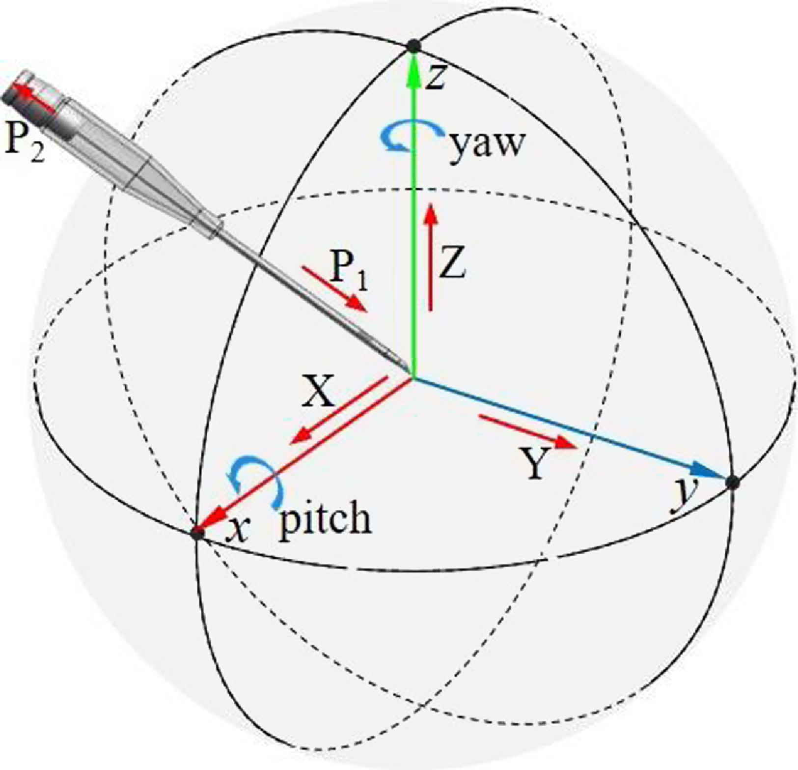
Figure 2. Analysis of puncture needle degrees of freedom.
Through the analysis of the traditional VPBC technology, it can be proved that the VPBC robot needs at least 5-DOF for position and orientation adjustment and 2-DOF for needle insertion to complete composite VPBC, as shown in Fig. 2. Based on the guidance of medical staff, the mechanical performance indexes required by the venipuncture robot were formulated considering the differences in the size and depth of human elbow veins and the accuracies of venography, mechanical structures, and robot control, as shown in Table I.
2.2. Rigid-flexible composite puncture strategy
Bother and traditional artificial venous blood collection and existing VPBC robots employ rigid needles for puncture blood collection [Reference Koskinopoulou, Cheng, Acemoglu, Caldwell and Mattos21, Reference Chen, Balter, Maguire and Yarmush22], as shown in Fig. 3 (a). The rigid needle is inserted into the skin, tissues, and blood vessels at an angle of 30° ∼ 45°, as shown in Fig. 3(i). Once the rigid needle pierces through the blood vessels, the puncture angle is reduced to about 18°, as shown in Fig. 3(ii). The rigid needle continues to advance about 5 mm before halting the puncture and commencing the blood collection procedure. Throughout the puncture process, the robot relies on real-time imaging guidance provided by an imaging system. It is important to continually guide the rigid needle using the real-time imaging system to ensure puncture accuracy. Furthermore, there exists a risk of inadvertently puncturing the blood vessel’s lower wall during the needle insertion stage, which may result in blood collection failure, as shown in Fig. 3(iii).
Therefore, this study proposes a RFCP strategy, as shown in Fig. 3 (b). A trocar needle, which consists of a rigid needle and a flexible tube, is applied to pierce the skin, tissues, and blood vessels at an angle of 20° ∼ 30°, as shown in Fig. 3(iv). Once the blood vessels are penetrated, the trocar needle enters the vein, as shown in Fig. 3(v). Subsequently, the rigid needle is retracted by about 10 mm, which ensures the rigid needle retracts into the flexible tube. Then, the trocar needle is advanced by approximately 5 mm in the blood vessel, as shown in Fig. 3(vi), allowing for the extraction of the rigid needle from the flexible tube and enabling the commencement of blood collection.
Compared to rigid needle punctures, the RFCP for blood collection has several advantages. The rigid needle is retracted into the flexible tube after the trocar needle penetrates the tissues and blood vessels. This design ensures that the needle does not pierce blood vessel’s lower wall during the insertion process, which could decrease blood collection failure rate, as shown in Fig. 3(vi). Moreover, due to the protection of the flexible tube, the trocar needle does not require real-time guidance from the imaging system after entering the blood vessel, reducing dependence on the imaging system. Based on the functional requirements analysis and the RFCP strategy, a workflow suitable for the VPBC robot is proposed, as shown in Fig. 4.
Table I. Mechanical performance indexes.


Figure 3. Workflow of the venipuncture robot. (a) Rigid needle puncture blood collection process. (b) RFCP strategy.

Figure 4. Workflow of the venipuncture robot.
2.3. Mechanical structure design of the venipuncture robot
This section designed the auxiliary VPBC robot for composite puncture blood collection based on the RFCP strategy proposed in Section 2.2, including the position and orientation adjustment mechanism and the RFCP end-effector.
2.3.1 Position and orientation adjustment mechanism
The purpose of the position and orientation adjustment mechanism is to adjust the position and orientation of the puncture needle according to the venous vessel imaging. The mechanism has 5-DOF, as shown in Fig. 5 (a), including three sliding pairs along the X, Y, and Z axes, a rotating pair around the Z-axis, and a rotating pair around the X-axis. Three sliding pairs can adjust the position of the puncture needle. The rotating pair around the Z-axis can adjust the yaw angle α of the puncture needle, as shown in Fig. 5 (b). The rotating pair around the X-axis realizes the adjustment of the pitch angle β, as shown in Fig. 5 (c). The 5-DOF position and orientation adjustment mechanism uses a minimum number of degrees of freedom to achieve needle position and orientation adjustment. The number of driving motors and the size of the robot are greatly reduced, which can reduce the control difficulty and realize the lightweight and miniaturized design.

Figure 5. (a) 3D model of the venipuncture robot. (b) Yaw angle adjusting mechanism. (c) Pitch angle adjusting mechanism.
2.3.2 Rigid-flexible composite puncture end-effector
The main purpose of the RFCP end-effector is to hold the trocar needle to complete the RFCP as shown in Fig. 6 (a). Motor 6 drives the trocar needle to advance, motor 7 drives the rigid needle to withdraw, and the force sensor collects the axial force of the puncture needle in real time. During the composite puncture, motor 6 drives the trocar needle to penetrate the skin, tissue, and blood vessels. After the trocar needle enters the blood vessels, motor 7 drives connector 2 to retreat with the rigid needle for about 5 mm, so that the needle tip of the rigid needle is retracted into the flexible tube to avoid puncture of the blood vessel’s lower wall during the needle insertion process. Subsequently, motor 6 drives the trocar needle to continue to advance in the blood vessels for about 5 mm. The motor 7 drives connector 2 to withdraw from the flexible tube with the rigid needle, and connect the vacuum tube to start blood collection. After the blood collection is completed, motor 6 drives the trocar needle to withdraw. Throughout the process of needle insertion, the force sensor collects the force information of the trocar needle and then judges the stage of the puncture needle. Fig. 6 (b) and (c) represent the trocar needle puncture into the blood vessel stage and the needle insertion stage with flexible tube protection.

Figure 6. (a) 3D model of the puncture device. (b) Trocar needle puncture stage. (c) The needle insertion stage with flexible tube protection.
3. Robot kinematics modeling
Robot kinematics analysis is the basis of robot motion control [Reference Dai, Zhang, Jiang and Li23, Reference Jiang, Zuo, Zhang, Huang, Guo and Xu24]. As the end-effector of the VPBC robot, the puncture needle needs to be analyzed kinematically. Based on the robot model, a position and orientation transformation coordinate system (Fig. 7) was established to describe the motion relationship of each joint.

Figure 7. Position and orientation transformation coordinate system of the venipuncture robot.
3.1. Forward kinematics
The forward kinematics problem of the VPBC robot is to analyze the motion law of each joint motion variable and the geometric dimensions of each link and to solve the position and orientation of the needle tip relative to the reference coordinate system [Reference Qin, Ji, Cheng, Zhao, Pan, Shi and Song25]. Based on the robot coordinate system, the Modified Denavit-Hartenberg (MDH) parameters are established, as shown in Table II.
According to the definition of the MDH method, the homogeneous transformation matrix between any adjacent link O i is as follows:
 \begin{align} {}^{0}{\boldsymbol{T}}{_{n}^{}}&=Rot\!\left(x,\alpha _{i-1}\right)\textit{Trans}\!\left(a_{i-1},0,0\right)Rot\!\left(z,\theta _{i}\right)\textit{Trans}\!\left(0,0,d_{i}\right)\nonumber\\[5pt] &=\left[\begin{array}{c@{\quad}c@{\quad}c@{\quad}c} c\theta _{i} & -s\theta _{i} & 0 & a_{i-1}\\[5pt] s\theta _{i}c\alpha _{i-1} & c\theta _{i}c\alpha _{i-1} & -s\alpha _{i-1} & \; -d_{i}s\alpha _{i-1}\\[5pt] s\theta _{i}s\alpha _{i-1} & c\theta _{i}s\alpha _{i-1} & c\alpha _{i-1} & d_{i}c\alpha _{i-1}\\[5pt] 0 & 0 & 0 & 1 \end{array}\right] \end{align}
Where, sθ i = sin(θ i ), cθ i = cos(θ i ), sα i-1 = sin(α i-1), cα i-1 = cos(α i-1), d i is the length of the connecting rod; α i-1 is the rotation angle of the adjacent coordinate system transformation around the x i-1 axis, θ i is the rotation angle of the adjacent coordinate system transformation around the z i axis. From the homogeneous transformation matrix between adjacent joints, the spatial position and orientation transformation matrix of the tip relative to the system base coordinate can be easily obtained:
 \begin{align} {}^{0}{\boldsymbol{T}}{_{n}^{}}&={}^{0}{\boldsymbol{T}}{_{1}^{}}{}^{1}{\boldsymbol{T}}{_{2}^{}}{}^{2}{\boldsymbol{T}}{_{3}^{}}{}^{3}{\boldsymbol{T}}{_{4}^{}}{}^{4}{\boldsymbol{T}}{_{5}^{}}{}^{5}{\boldsymbol{T}}{_{6}^{}}{}^{6}{\boldsymbol{T}}{_{n}^{}}=\left[\begin{array}{c@{\quad}c} {}^{0}{\boldsymbol{R}}{_{n}^{}} & {}^{0}{\boldsymbol{P}}{_{n}^{}}\\[5pt] 0 & 1 \end{array}\right]=\left[\begin{array}{c@{\quad}c@{\quad}c@{\quad}c} n_{x} & o_{x} & a_{x} & p_{x}\\[5pt] n_{y} & o_{y} & a_{y} & \; p_{y}\\[5pt] n_{z} & o_{z} & a_{z} & p_{z}\\[5pt] 0 & 0 & 0 & 1 \end{array}\right]\nonumber\\[5pt] &=\left[\begin{array}{c@{\quad}c@{\quad}c@{\quad}c} c_{4} & -\mathrm{s}_{4}\cdot c_{5} & s_{4}\cdot s_{5} & p_{x}\\[5pt] s_{4} & c_{4}\cdot c_{5} & -c_{4}\cdot s_{5} & \; p_{y}\\[5pt] 0 & s_{5} & c_{5} & p_{z}\\[5pt] 0 & 0 & 0 & 1 \end{array}\right] \end{align}
According to the forward kinematics equation of the needle tip at the end of the VPBC robot, the workspace is drawn and shown in Fig. 8. The blue point cloud in Fig. 8 denotes the reachable workspace of the VPBC robot, and the red area represents the target workspace. From the projections of the robot workspace in Fig. 8 (b), (c), and (d), it can be seen that the robot workspace can meet the needs of venipuncture.
Table II. MDH parameter table of venipuncture robot.
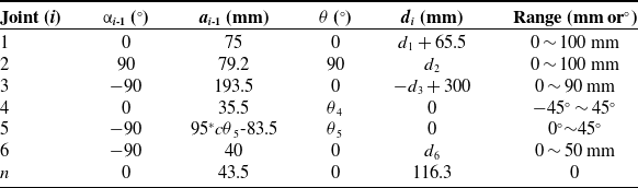

Figure 8. Workspace of the venipuncture robot. (a) The 3D workspace. (b) X–Y plane projection. (c) X–Z plane projection. (d) Y–Z plane projection.
3.2. Inverse kinematics
The inverse kinematics problem is to solve the motion parameters of each joint variable of the venipuncture robot when the position and orientation of the puncture point relative to the reference coordinate system are known. At present, the conventional methods for solving inverse kinematics include analytical solutions, numerical solutions, and intelligent algorithms. The geometric structure of the VPBC robot designed in this paper does not satisfy the Pieper criterion [Reference Liu, Xi, Bai, Wang and Sun26, Reference Wang, Cao, Wang and Yu27], and a closed analytical solution cannot be solved. The commonly used numerical solution to robot inverse kinematics is an iterative algorithm, which calculates the Jacobian matrix of the robot, and then calculates the exact solution iteratively by given initial values [Reference Han, Yin and Liu28, Reference Guo, Zhu and Wang29]. However, for some special positions and orientations, the VPBC robot would be in the singularity of the Jacobian matrix and cannot be used numerical solutions for solving inverse kinematic solutions.
In this paper, an intelligent algorithm is used to establish a fitness function with the minimum position and orientation error of the needle tip as the optimization index. The problem of solving the inverse kinematics nonlinear equation is transformed into an optimization problem and solved by DE algorithm [Reference Xie, Fan and Zhou30, Reference Dong, Li and Yao31]. The robot joint variables d 1, d 2, d 3, θ 4, θ 5, and d 6 are selected as the solution sets of the DE algorithm so that the target can obtain an optimal solution set within robot joint variables, and the end position and orientation error is minimized. In other words, the value of the adaptive function is the smallest.
The selected solution set is brought into Eq. (3) to obtain the position and orientation matrix ${}^{0}{T}{_{n}^{\prime}}$
. Then, the position error ΔP and orientation error ΔR of the needle tip are obtained. The formula is as follows:
${}^{0}{T}{_{n}^{\prime}}$
. Then, the position error ΔP and orientation error ΔR of the needle tip are obtained. The formula is as follows:
 \begin{equation} {}^{0}{\boldsymbol{T}}{_{n}^{\prime}}=\left[\begin{array}{c@{\quad}c} {}^{0}{\boldsymbol{R}}{_{n}^{\prime}} & {}^{0}{\boldsymbol{P}}{_{n}^{\prime}}\\[5pt] 0 & 1 \end{array}\right]=\left[\begin{array}{c@{\quad}c@{\quad}c@{\quad}c} n_{x}^{\prime} & o_{x}^{\prime} & a_{x}^{\prime} & p_{x}^{\prime}\\[5pt] n_{y}^{\prime} & o_{y}^{\prime} & a_{y}^{\prime} & \; p_{y}^{\prime}\\[5pt] n_{z}^{\prime} & o_{z}^{\prime} & a_{z}^{\prime} & p_{z}^{\prime}\\[5pt] 0 & 0 & 0 & 1 \end{array}\right] \end{equation}
 \begin{equation} \left\{\begin{array}{l} \Delta P=\sqrt{\left(p_{x}^{\prime}-p_{x}\right)^{2}+\left(p_{y}^{\prime}-p_{y}\right)^{2}+\left(p_{z}^{\prime}-p_{z}\right)^{2}}\\[5pt] \Delta R=\sqrt{\Delta n^{2}+\Delta o^{2}+\Delta a^{2}} \end{array}\right. \end{equation}
The construction of the adaptive function is related to the position error and orientation error, and the orientation error is associated with the joint space. The value range of the joint vector element is [−1,1], and the position error is related to the range of the workspace. The range can be determined according to the distribution of the workspace. Therefore, the measurement benchmark between the two errors is different. Error convergence imbalance needs to be solved by weighting the two errors [Reference Elsayed, Sarker and Essam32, Reference Tam, Linh and Nguyen33]. The adaptive function is as follows:
 \begin{equation} f=\gamma _{P}\cdot \Delta P+\gamma _{R}\cdot \Delta R \end{equation}
where γ P is the position error weight coefficient, and γ R is the orientation error weight coefficient. The inverse motion of the DE algorithm can be solved according to this adaptive function.
3.3. Verification of the forward and inverse solution
Based on the above analysis, the mechanism scale parameters mainly include d 1, d 2, d 3, θ 4, θ 5, and d 6. The optimization goal of this study is to determine the combination of mechanism input parameters according to the desired output position and orientation. The input parameters (d 1, d 2, d 3, θ 4, θ 5, d 6) in Eq. (6) are solved by the DE algorithm proposed in [Reference Das and Suganthan34]. It can be observed that the decision variables in the process of solving the inverse solution of the mechanism position are:
 \begin{equation} \boldsymbol{x}=\left(x_{1},x_{2},\cdots,x_{n}\right)^{\mathrm{T}}=\left(d_{1},d_{2},d_{3},\theta _{4},\theta _{5},d_{6}\right)^{\mathrm{T}} \end{equation}
The optimal target function of the inverse solution of the mechanism position is:
 \begin{equation} \min f\!\left(\boldsymbol{x}\right)=\gamma _{P}\cdot {\Delta} P+\gamma _{R}\cdot {\Delta} R \end{equation}
The control parameters of the DE algorithm for solving inverse position are N P = 40, D = 6, C R = 0.85, F = 0.5, and T = 1000. In this paper, the algorithm ends when the current evolution time t = T. The value ranges of the variables to be determined are x max = [100, 100, 90, π/4, π/4, 50], x min = [0, 0, 0, −π/4, 0, 0], and the acceptable error f ac = 10−10. The DE algorithm of the literature [Reference Mayer, Kinghorn and Archer35, Reference Elsayed, Sarker and Essam36] is run independently, and the obtained inverse solution parameters of the mechanism position are shown in Table III.
Table III. Robot inverse solution.

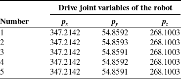
To verify the correctness of the inverse position solution, five groups of inverse solutions were introduced into 0 T n to obtain the corresponding tip position (Table IV). Within the allowable error range, the robot inverse solution is consistent with the given robot end position, which proves the effectiveness of the inverse solution method.
Table IV. Verification of robot inverse solution.
3.4. Trajectory planning
3.4.1 Trajectory planning using quintic polynomial interpolation
The trajectory of the VPBC robot can be divided into two segments. The first segment is the movement of the puncture needle from the initial point A to the puncture starting point B, and the second is the movement from the puncture starting point B to the puncture end point C. Since the puncture needle needs to move to the puncture starting point in the desired position and orientation, this paper utilizes the joint space planning method to plan the robot’s trajectory, using joint variable functions to describe the robot trajectory. Quintic polynomial interpolation is used for joint trajectory planning to ensure the continuity of puncture speed and acceleration [Reference Piazzi and Visioli37, Reference Shafaat and Bertrand38]. According to the pose P 0 of the puncture needle at the initial point, the pose P j of the puncture starting point, and the pose P n of the puncture end point, the position p ij of each joint i at time t j is obtained through inverse kinematics, that is,
 \begin{equation} \boldsymbol{P}=\left(p_{i\mathit{j}}, t_{j}\right),\quad i=0,1,\ldots,6.\quad \mathit{j}=0,1,\ldots, n. \end{equation}
The continuous joint trajectory planning is obtained through quintic polynomial interpolation of the sequence of each joint position and time of the robot.
 \begin{equation} p_{i}\!\left(t_{j}\right)=a_{i\mathrm{5}}{t_{j}}^{\mathrm{5}}+a_{i\mathrm{4}}{t_{j}}^{4}+a_{i\mathrm{3}}{t_{j}}^{\mathrm{3}}+a_{i\mathrm{2}}{t_{j}}^{\mathrm{2}}+a_{i\mathrm{1}}t_{j}+a_{i\mathrm{0}} \end{equation}
Then the velocity and acceleration of each joint of the robot on trajectory are
 \begin{equation} \left\{\begin{array}{l} p_{i}^{\prime}\!\left(t_{j}\right)=5a_{i\mathrm{5}}t_{j}^{4}+\mathrm{4}a_{i\mathrm{4}}t_{j}^{3}+\mathrm{3}a_{i\mathrm{3}}t_{j}^{2}+\mathrm{2}a_{i\mathrm{2}}t_{j}+a_{i\mathrm{1}}\\[5pt] p_{i}^{\prime\prime}\!\left(t_{j}\right)=20a_{i\mathrm{5}}t_{j}^{3}+\mathrm{12}a_{i\mathrm{4}}t_{j}^{2}+\mathrm{6}a_{i\mathrm{3}}t_{j}+\mathrm{2}a_{i\mathrm{2}} \end{array}\right. \end{equation}
To realize the start and stop control of the robot at positions A, B, and C, the constraints of angle (displacement), angular (displacement) velocity, and angular (displacement) acceleration of each joint are set as shown in Eq. (11).
 \begin{equation} \left\{\begin{array}{l} \mathit{p}_{i}\!\left(\mathit{t}_{0}\right)=p_{i\mathrm{0}},\mathit{p}_{i}\!\left(\mathit{t}_{\mathit{j}}\right)=p_{ij}, \\[5pt] \mathit{p}_{i}^{\prime}\!\left(\mathit{t}_{0}\right)=p_{i0}^{\prime},\mathit{p}_{i}^{\prime}\!\left(\mathit{t}_{\mathit{j}}\right)=p_{ij}^{\prime},\\[5pt] \mathit{p}_{i}^{\prime\prime}\!\left(\mathit{t}_{0}\right)=p_{i\mathrm{0}}^{\prime\prime},\mathit{p}_{i}^{\prime\prime}\!\left(\mathit{t}_{\mathit{j}}\right)=p_{ij}^{\prime\prime}, \end{array}\right. \end{equation}
Substitute the constraints of each robot joint into Eqs. (9) and (10) to determine the coefficients of the trajectory function p i (t j ) of each joint.
 \begin{equation} \left\{\begin{array}{l} a_{i0}=0,\\[5pt] a_{i1}=p_{i0}^{\prime},\\[5pt] a_{i2}=p_{i0}^{\prime}/2,\\[5pt] a_{i3}=\frac{20\left(p_{ij}-p_{i\mathrm{0}}\right)-\left(8p_{ij}^{\prime}+12p_{i0}^{\prime}\right)t_{j}-\left(3p_{i\mathrm{0}}^{\prime\prime}-p_{ij}^{\prime\prime}\right)t_{j}^{2}}{2t_{j}^{3}},\\[5pt] a_{i4}=\frac{30\left(p_{i\mathrm{0}}-p_{ij}\right)+\left(14p_{ij}^{\prime}+16p_{i0}^{\prime}\right)t_{j}+\left(3p_{i\mathrm{0}}^{\prime\prime}-2p_{ij}^{\prime\prime}\right)t_{j}^{2}}{2t_{j}^{4}},\\[5pt] a_{i5}=\frac{12\left(p_{ij}-p_{i\mathrm{0}}\right)-6\!\left(p_{ij}^{\prime}+p_{i0}^{\prime}\right)t_{j}-\left(p_{i\mathrm{0}}^{\prime\prime}-p_{ij}^{\prime\prime}\right)t_{j}^{2}}{2t_{j}^{5}}, \end{array}\right. \end{equation}
3.4.2 Trajectory planning simulation
In this section, the trajectory planning simulation of the puncture needle is performed, and three nodes on the puncture path are selected: initial point A, puncture starting point B, and puncture end point C. The poses are shown in Table V. Among them, the orientation is the yaw angle α and pitch angle β of the puncture needle, and the position is the coordinate value of the needle tip in the base coordinate (p x , p y , p z ). By substituting the fitting point poses of the puncture trajectory planning in Table V into the DE algorithm in Section 3.2, the changes in each joint can be obtained, and simulation software is used for trajectory planning.
Table V. The position and orientation of the trajectory planning fitting point.


Figure 9. Trajectory planning of the venipuncture robot. (a)–(c) Trajectory planning timing diagram of the venipuncture robot. (d) Variation curve of each joint. (e) The velocity curve of each joint. (f) Acceleration curve of each joint.
Import the 3D model of the venipuncture robot in Unified Robot Description Format (URDF) format into the simulation software and use the quintic polynomial interpolation function in the software to interpolate the joint drive angles (displacements) corresponding to the three feature points. Motion simulation is performed in the software. The time of the entire motion process is set to t = 10 s. The trajectory of the puncture needle end, the joint angle (displacement) of each joint, the joint angle (displacement) velocity, and the joint angle (displacement) acceleration change curve as shown in Fig. 9. The speed and acceleration curves of each joint of the puncture robot are relatively continuous and smooth, proving that there are no sudden changes in the robot’s movement and no singular points on the trajectory.
4. Experiment and validation
4.1. Robot system
According to the analysis and design mentioned above, this paper developed a prototype of the auxiliary VPBC robot, as shown in Fig. 10(a). The prototype is sized (450 × 450 × 525) mm3. The base and bracket are made of aluminum alloy profile, and the connectors are made of 6061 aluminum alloy. The drive motor is a closed-loop stepper motor, and the sliding pair uses a precision linear module with an accuracy of less than 0.05 mm. The motion controller is controlled by high-end eight-axis motion control cards. The force sensor uses a thin-film pressure sensor with a range of 0-6N.
4.2. Trajectory planning of the venipuncture robot
According to the trajectory planning in section 3.2, the VPBC robot was used to perform trajectory planning experiments on the phantom arm. Input the time series of joint changes into the PC interface program to drive the trocar needle to puncture along the planned trajectory to complete VPBC. The experimental results are shown in Fig. 11. The trocar needle completes the position and orientation adjustment from the initial point A along the trajectory AB to the puncture starting point B and then starts the puncture to reach the puncture end point C. The trocar needle trajectory obtained in the experiment is consistent with the trajectory obtained in the simulation, which proves the effectiveness of trajectory planning.

Figure 10. Prototype of the venipuncture robot. (a) The venipuncture robot. (b) The screw module and drive. (c) The motion control card. (d) The force sensor.
4.3. Composite puncture blood collection experiment on the phantom arm
We performed a venipuncture experiment on the phantom arm to test the robot’s performance. The skin of the phantom arm is made of silicone. It has a silicone hose inside and a red liquid with a pressure of 10 mmHg in the hose to simulate blood. The diameter of the silicone hose is 4 mm, the wall thickness is 0.5 mm, and it is located 3 mm under the skin of the phantom arm. The size of the venipuncture needle is Φ0.7*19 mm.
In the experiment, the three-dimensional coordinates of the target puncture point on the phantom arm were obtained through measurement and calculation. Then, trajectory planning is performed so that the trocar needle moves to the puncture starting point with an orientation of 0° yaw angle and 30° pitch angle. Perform composite puncture according to the VPBC robot workflow in section 2.2 until red liquid appears in the flexible tube, as shown in Fig. 12 (a). Insert the other end of the trocar needle into the vacuum blood collection tube, and the red liquid flows into the vacuum blood collection tube under the pressure difference, as shown in Fig. 12 (b). During the experiment, if an error occurs, the robot can be stopped immediately through the “Stop” button on the PC interface to avoid secondary injury. The entire experimental process took about 25 s. The robot successfully punctured the target point and collected red liquid in the vacuum tube in 20 simulated puncture experiments, which proved the feasibility of the RFCP strategy.

Figure 11. Path planning experiment of the venipuncture robot. (a) Initial state. (b) Position and orientation adjustment stage. (c) Puncture stage.

Figure 12. Venipuncture experiment on phantom arm. (a) Robot performs puncture. (b) The vacuum tube collects red liquid.
5. Conclusions
The venous blood test is a prevalent medical auxiliary diagnostic method that aids in disease diagnosis and treatment. The venous blood collection equipment can improve blood collection’s success rate and stability, reduce the workload of medical staff, and improve the efficiency of diagnosis and treatment. This paper proposed an RFCP strategy, which uses the rigid needle and flexible tube of the trocar needle to replace the traditional rigid needle puncture. A small 7-DOF auxiliary VPBC robot composed of a position and orientation adjustment mechanism and an RFCP end-effector was designed based on this strategy. It can perform RFCP and avoid pierceing the blood vessel’s lower wall during puncture. Then, the robot kinematic analysis was performed and the inverse kinematic solution of the robot was solved using the DE algorithm. The trajectory planning control was implemented using quintic polynomial interpolation algorithm. Finally, a VPBC robot prototype was developed, and trajectory planning experiments and composite puncture and blood collection experiments were conducted. In the experimental results, the VPBC robot followed the set trajectory from the initial point to the puncture starting point and moved smoothly without oscillations. In addition, the VPBC robot can also successfully collect simulated blood from the blood vessels of the phantom arm using the RFCP strategy. The experiment result verified the correctness of the inverse kinematic solution and trajectory planning and the feasibility of the RFCP strategy. The results in this paper are based on the phantom arm. The phantom arm has biological properties similar to the human arm, but cannot fully simulate a real puncture situation. Next, we plan to use animal experiments to study the actual situation of composite puncture.
In future work, we will optimize the VPBC robot’s design and verify the effect of the RFCP in animal experiments. Study the puncture force model during the composite puncture process and integrate it with the vein imaging system to guide the auxiliary VPBC robot to perform puncture blood collection.
Author contributions
Shikun Wen assisted in the puncture experiment of the phantom arm. Qian Qi assisted in structural design and selection and processing of parts. Zhikang Yang wrote the relevant content of the manuscript and designed the algorithm. Aihong Ji and Zhuhai Lv supervised and guided the progress and design ideas of the project and provided funds. All authors guided the writing of the paper.
Financial support
This work was supported by the Research Fund of State Key Laboratory of Mechanics and Control for Aerospace Structures (1005-IZD23002-25).
Competing interests
The authors declare no competing interest exists.
Ethical approval
Not applicable.


