


1 INTRODUCTION
For more than two decades, the astronomical community has recognised the need for a major new radio observatory to succeed the current generation of radio telescopes, and to surpass their sensitivity and resolution. The Square Kilometre Array (SKA) was conceived in the early 1990s (Carilli & Rawlings Reference Carilli and Rawlings2004) and is now embodied in The SKA OrganisationFootnote 1 , which is coordinating the design and construction of major new radio telescopes.
ASKAP, the Australian SKA Pathfinder (DeBoer et al.; Reference DeBoer2009, Johnston et al.; Reference Johnston2007), is one of several radio telescopes being built to explore and demonstrate possible new approaches to design the SKA itself. ASKAP is located at the Murchison Radio Observatory (MRO) in Western Australia, and is being constructed by CSIRO—the Commonwealth Scientific and Industrial Research Organisation. It is designed as a survey telescope that can rapidly image the entire available sky. It operates over the 0.7–1.8 GHz range and will achieve its survey speed by virtue of small antennas (12-m diameter) and the use of phased array feeds (PAFs) to sample a large portion (approximately 0.64 m2) of the focal plane. Other SKA precursors include the Murchison Widefield Array (MWA) (Tingay et al. Reference Tingay2013), also located at the MRO, and the South African array MeerKAT (Jonas Reference Jonas2009).
The PAF is the critical new technology being explored on ASKAP. A PAF is a dense array of sensors placed in the focal plane of each antenna. Digital beamformers synthesise ‘formed’ beams as linear combinations of signals from the individual sensors. With a suitable choice of weights—the complex coefficients used in the linear sum—beams can be formed to point anywhere within the available field-of-view, 5.5° × 5.5° in the case of ASKAP. Verheijen et al. (Reference Verheijen, Oosterloo, van Cappellen, Bakker, Ivashina and van der Hulst2008) describe APERTIF (APERture Tile In Focus), another exploratory project, which is equipping antennas of the WSRT (Westerbork Synthesis Radio Telescope) with PAFs.
Here, we describe the operation and performance of a prototype of ASKAP, the Boolardy Engineering Test Array (BETA), comprising six of the ASKAP antennas. The full description of BETA by Hotan et al. (Reference Hotan2014) is recommended reading to set the context of this account of its performance.
The reliance of ASKAP on such a novel technology has risks, many of which may be reduced by the establishment of BETA as a functioning prototype capable of astronomical observations. Questions to be answered by experiment with BETA include:
-
• Can beams be formed with only small antennas? The beams are formed as a linear combination of the signals from individual PAF sensors, specified as a set of complex weights. Determination of the optimum set of weights requires a measure of the response of each sensor, which in turn requires a sufficiently strong source of radiation to provide a measurable response.
-
• Are the beams stable, and are the time scales for beam degradation long compared with the practical interval for determination of beam weights?
-
• Can the antenna pointing be measured? Traditionally, the single stable beam aligned with the antenna’s optical axis provides the reference for the assessment of mechanical pointing accuracy.
-
• Can variations in the antenna-to-antenna beam shape be made small enough not to limit dynamic range?
-
• Can the instrumental polarisation be calibrated and corrected over the whole field-of-view?
-
• Is the expected field-of-view realised?
-
• Can the antenna gains (beam and frequency specific) be determined with a small number of small antennas?
-
• Can an instrument of this complexity operate with the reliability required for uniform all-sky surveys?
Outline
After giving a brief description of BETA and its commissioning (Section 2), we follow a logical sequence through the methods and results of its operation: calibration of the array (antenna locations and pointing) in Section 3; beamforming and beam measurement in Section 4; observations, including those required for calibration of antenna gains in Section 5; calibration of visibility data for the instrument’s response and imaging those data in Section 6. In Section 7, we present details of BETA’s perfomance: sensitivity, beam characteristics, polarimetric properties, and image quality. In Section 8, we briefly summarise the use of BETA and point to the future operation of ASKAP, drawing on the experience gained with BETA.
2 COMMISSIONING AND FIRST SCIENCE
2.1. BETA the telescope
BETA operated as an aperture synthesis telescope from 2014 March until it was decommissioned in 2016 February. The parameters of BETA are summarised in Table 1, reproduced from Hotan et al. (Reference Hotan2014). The BETA PAF is a dual-polarisation connected-array antenna (Hay & O’Sullivan Reference Hay and O’Sullivan2008; Hay, O’Sullivan, & Mittra Reference Hay, O’Sullivan and Mittra2011) with 2 × 94 sensors in a ‘chequerboard’ pattern. It is the first version (Mark I) of the CSIRO PAF (Schinckel et al. Reference Schinckel, Bunton, Chippendale, Gough, Hampson, Hay, Jackson, Jeganathan, O'Sullivan, Reynolds, Shaw and Wilson2011), and will be superceded in the final ASKAP telescope by the Mark II, which has better and more consistent noise properties across its frequency range (Chippendale et al. Reference Chippendale2015).
Table 1. Key parameters of the BETA telescope.

a Natural weighting, 1.1–1.4 GHz.
BETA comprises six of the 36 ASKAP antennas. Each has conventional vertical and horizontal (azimuth and elevation) rotation axes, and a third axis—the ‘roll’ axis—that is collinear with the antenna’s optical axis or ‘boresight’. Motion about the roll axis allows the antenna’s response pattern to be kept fixed on the sidereal sky.
For each antenna, the digital beamformers can synthesise nine dual-polarisation beams at each of the 304 coarse (1 MHz) frequency channels across the observed band. After further division of the spectrum into 16 416 fine frequency channels, the correlator computes, for all four polarisation products (XX, XY, YX, YY), visibilities for all nine beams across the six-antenna array.
BETA implements phase and delay tracking for a reference direction, common to all beams. This approach is feasible for BETA since all baselines are shorter than 1 000 m. ASKAP will phase-track a reference direction for each beam.
BETA lacks a system for injecting noise into the radio frequency signal. Such a system, which will be present on ASKAP, would be used for stabilising gain variations and for measuring the relative phase of signals in the X and Y polarisation channels. BETA has been operated without any gain stabilisation, and for polarimetric work the XY phase has been estimated by purposely misaligning one antenna about its roll axis.
A major component of ASKAP is ASKAPsoft (Cornwell et al. Reference Cornwell, Humphreys, Lenc, Voronkov and Whiting2011), the calibration and imaging software package that processes raw visibility data to produce images of the sky. Although the number of antennas and sensitivity of BETA was insufficient to test the full sky-model-based calibration approach designed for ASKAP, it provided a means to test the software with more traditional calibration methods, and has allowed direct comparison with existing radio astronomy imaging packages.
The use of PAFs greatly increases hardware complexity compared to other radio telescopes. With 188 active elements at the focus, the task of monitoring and control becomes a significant engineering exercise, the more so for needing to operate the telescope remotely. BETA has provided a platform to test the systems that were designed to cope with this complexity. Issues of scalability, logging efficiency, and the provision of adequate user feedback all arose during the operation of BETA and have influenced the design of the final system to be used on ASKAP.
2.2. Operational performance
ASKAP is built on a remote and isolated site. The MRO is located in a sparsely populated region of Western Australia, 380-km north-east by road from the town of Geraldton. Support staff are based in Geraldton and, whilst construction continues, travel to the Observatory by road or air for several days of most weeks. The Observatory is unstaffed at other times, and so the establishment of reliable operations is essential to the efficiency of ASKAP’s scientific programme. Most operations can be conducted remotely.
BETA has proven to be workable in this mode of operation, but several reliability issues highlighted the importance of developing robust systems for deployment in this harsh environment. The most serious examples were the MRO site power supply, and certain components of the systems for cooling PAFs and other antenna-based equipment.
Observatory power is provided by a set of diesel motor-generators, designed to be swapped without interruption to power. Over the commissioning period, the reliability of the power has steadily improved; interruptions experienced in 2015 were 10-fold fewer than in 2014.
The antenna-based electronics was cooled by air circulated through a water-cooled heat exchanger. Variation of water flow rate was used to stabilise the temperature of the equipment enclosures. These cooling systems, which usually ran at close to their capacity, gave a range of difficulties: water circulation pump burn-out; false alarms from over-temperature sensors; and power irregularities induced by start-up transients from the compressors. Although the mean time between failures in either site power or PAF cooling has been moderate (approximately 30 d), the impact on operations is greater than for failures in most other parts of the telescope because of the need for support staff to restore normal operation. Cooling systems for the Mark II PAFs and associated equipment have been redesigned.
The telescope performance has also proven to be relatively stable. We present results in Section 7 that are evidence for a pleasing level of stability in antenna pointing, in amplitude, phase and delay of the signal path, and in instrumental polarisation. The most significant areas of instability are an occasional loss of synchronisation in the correlator (e.g. Allison et al. Reference Allison2015), a diurnal gain-amplitude variation arising from imperfect PAF temperature stabilisation and some loss of coherence between PAF digital sample streams. The last issue is discussed in Section 7.2.
2.3. Interfering signals
ASKAP and the MRO are protected from ground-based sources of radio frequency interference (RFI) by the Australian Radio Quiet Zone WA (ARQZWA), established by the Australian and Western Australian Governments (Wilson, Storey, & Tzioumis Reference Wilson, Storey and Tzioumis2013; Australian Communications and Media Authority 2011). The Zone has three concentric parts with radii of 70, 150, and 260 km, which have graded regulations designed to minimise radio interference from ground-based sources. As a consequence of this protection and of the very low population density throughout the Zone, most RFI detected by BETA originated from navigation and communications satellites and from aircraft navigation systems.
The BETA spectrum shown in Figure 4 has several features identified with these airborne and orbiting sources of RFI. Allison et al. (in preparation) show the spectrum in more detail: Spectra over the 711.5–1527.5 MHz band from two astronomical sources have very similar patterns of RFI that are consistent with the spectrum in Figure 4. They report that about 14% of both spectra are corrupted by RFI.
2.3.1. Solar interference
The Sun is a source of radio interference and appears in BETA visibilities as broadband noise with phase structure characteristic of a source displaced from the Array’s delay tracking centre (Hotan et al. Reference Hotan2014). Over the 711.5–1015.5-MHz band, we explored the circumstances that led to the greatest levels of solar interference by recording visibilities from directions over a coarsely spaced ( ~ 15°) range of angular displacements θ⊙ from the Sun. The spectrum of each visibility measurement was Fourier-transformed to produce a delay spectrum in which the solar signal is easily identified at the delay corresponding to its angular displacement from the delay centre. We estimated the absolute strength of the solar signal by comparison with a contemporaneous observation of the source PKS B0407–658, which has a flux density of 24.4Jy at 843 MHz (Mauch et al. Reference Mauch, Murphy, Buttery, Curran, Hunstead, Piestrzynski, Robertson and Sadler2003). The results are summarised in Figure 1. The solar signal is greatest on short baselines; the Sun’s 0.5° disk is resolved for baselines much longer than ~ 60λ. Solar interference is greatest when θ⊙ ≲ 20° and 80° ≲ θ⊙ ≲ 130°. When θ⊙ lies in the range [90°, 130°], the sun shines directly onto the surface of the PAF; at greater angles, the PAF is shadowed by the antenna’s primary reflector.

Figure 1. The strength of solar interference detected in BETA visibilities as a function of projected baseline length and the Sun’s displacement θ⊙ from the pointing direction. When θ⊙ lies between the two dashed lines, the Sun shines directly onto the surface of the PAF. At greater angles, the PAF is shadowed by the antenna’s primary reflector. The contours are at 5, 10, 20, and 40 Jy. No measurements were made at θ⊙ < 15°.
2.4. First science
The scientific programme of ASKAP is based on a set of Survey Science Projects (SSP) that cover a broad range of radio surveys of the sky (Johnston et al. Reference Johnston2007). Up to 75% of ASKAP time will be dedicated to these projects. Although BETA, with its few 12-m antennas and the relatively poor sensitivity of the Mark I PAFs at frequencies ≳ 1.2 GHz, was not expected to produce major scientific contributions, the wide instantaneous field-of-view and access to the 0.7–1.8 GHz portion of the spectrum from a radio-quiet site gave the potential for some scientifically useful results. Therefore, the commissioning team included active members of several of the SSPs, adding scientific incentive to the motivation for the commissioning activities and resulting in six refereed scientific publications.
The higher sensitivity part of BETA’s spectrum corresponds to frequencies of the Hi line at redshifts of 0.4 < z < 1.0. Allison et al. (Reference Allison2015) report the first detection of strong Hi absorption at z = 0.44 associated with the young radio galaxy PKS1740-517. Contrary to the normal sequence, the redshift of this system was measured first in the radio, and later confirmed in optical spectra.
Serra et al. (Reference Serra2015) report observations at 1.4 GHz of the galaxy group IC 1459. BETA’s nine beams at 1.4 GHz covered 6 deg2, within which Hi emission was detected from 11 of the galaxies in the group. Three previously undetected Hi clouds were discovered in the BETA images.
One of the scientific objectives of ASKAP is to detect transient radio emission on various time scales. To explore this capability, BETA was used to image a field containing the intermittent pulsar PSR J1107-5901 already known to exhibit marked ‘on’ and ‘off’ states. The result was the successful detection of several state transitions in a series of 390 2-min images, reported in full by Hobbs et al. (Reference Hobbs2016).
Much of BETA’s commissioning work has focussed on continuum imaging of large areas of sky, a capability required by several of ASKAP’s SSPs. Heywood et al. (Reference Heywood2016) present the results from repeated observations of a 150-deg2 field in the constellation Tucana. Three 12-h observations were made, with each observation being two sets of six pointings, offset to achieve the interleaving described below in Section 5. From the resulting images, Heywood et al. prepared a new catalogue of 3 722 sources, giving positions, flux densities and, in many cases, spectral indices over the 711.5–1015.5-MHz observing band.
Harvey-Smith et al. (Reference Harvey-Smith2016) report detection by BETA of emission from the OH megamaser IRAS 20100-4156, confirmed by subsequent observations with the ATCA (Australia Telescope Compact Array). Their paper discusses the significance of changes in the emission spectrum since the first observation of this source by Staveley-Smith et al. (Reference Staveley-Smith, Allen, Chapman, Norris and Whiteoak1989).
BETA was used for part of the comprehensive search for an electro-magnetic counterpart to the gravitational wave (GW) event GW150914 reported by Abbott et al. (Reference Abbott2016a). BETA’s contribution to this campaign (Abbott et al. Reference Abbott2016b) was the imaging of approximately 270 deg2 of the most likely GW localisation. Observations were made with BETA over 18 h about 1 week after the GW event, and reached an image sensitivity of 1–5 mJy (rms).
3 INSTRUMENTAL CALIBRATION
3.1. Antenna positions
All ASKAP antenna locations in the horizontal plane were initially determined by conventional surveying techniques, with the vertical distance from the WGS 84 reference spheroidFootnote 2 also measured for the six BETA antennas. A standard method for refining these measurements is to observe several strong radio sources with well-known celestial positions, and use the interferometer phase on each baseline to derive corrections to the initial measurements. We used an equivalent and, for BETA, more robust technique of performing self-calibration of the visibilities for each source and fitting each antenna’s position (X, Y, Z in the International Terrestrial Reference Frame) to the phase of its complex gain. We used a simple point-source model of the field, but more complex models could have been used to allow calibration on confused fields. The observations were made using single-element beams to avoid measurement bias introduced by the comparatively poorly understood complex gains of the beams formed from many elements. The uncertainties in position corrections determined in this way are typically 0.5 mm in the X − Y plane, and 1.3 mm in Z.
Once the antenna locations were established, fixed (or slowly varying) antenna-specific delays were determined from a single observation of a strong source. These delays are determined with an accuracy of ~ 50 ps.
3.2. Antenna pointing
In a radiotelescope with a feed horn, the beam direction is fixed relative to the telescope’s structure and defines its pointing direction. Imperfections in the mechanical pointing can be determined by measuring the beam position on the sky relative to the known position of a strong source—a pointing calibrator. Any misalignment between the beam and the telescope’s optical axis is ultimately absorbed in the pointing model.
The ASKAP antennas form beams from a PAF; their direction relative to the antenna’s optical axis, and their shape, are determined by the weights used in the combination of the signal from each PAF element and by the (possibly time-variable) element characteristics. This introduces new sources of pointing error not related to the mechanical pointing performance of the antenna.
Two methods have been developed for pointing measurements on BETA, both using unique features of the ASKAP antennas. The first, used to determine coarse offsets on the azimuth and elevation motions, determines the location of the Sun’s image on the focal plane from the PAF element outputs. This method uses the antenna and its PAF as a radio ‘digital camera’. The image quality on the focal plane is imperfect because of the dispersion of PAF element characteristics, but is sufficient to correct the coarse pointing to an accuracy of ≲ 0.1°.
The second method uses the roll rotation axis of the ASKAP antennas as the reference direction for pointing calibration. The procedure uses beams formed from single PAF elements, which have fixed offsets from the boresight direction, but individually have less sensitivity than formed beams. By rotating the antenna being measured about its roll axis whilst pointing at a calibration source, and with knowledge of the size of single-element beams, the amplitudes of visibilities with a second fixed reference antenna can be modelled to give the misalignment of the roll-axis with the source direction—the pointing error. The procedure is executed twice for each calibration source; half the antennas are used as reference for measuring the other half, then these roles are reversed. Eight of BETA’s nine beamformers are used to make the measurements simultaneously with a symmetrical pattern of eight single elements in both polarisations.
Figure 2 shows the results of observations made to test the efficacy of this method. Pointing measurements were made repeatedly on a single source (PKS B1934–638) over a 7-h period, with pointing intentionally set with declination offsets of − 3, 0, +3 arcmin. Four antennas were used for the test, with each alternately being measured or serving as reference. Twenty six pointing scans were conducted over the 7 h, resulting in 13 measurements for each antenna. From these results, we estimate the uncertainties in pointing error determination to be ΔHA/cosδ = 0.4, Δδ = 0.3 arcmin. A full description of both methods can be found in the report by McConnell, Hotan, & Kesteven (Reference McConnell, Hotan and Kesteven2015).

Figure 2. Results from the declination offset test that is described here, for antennas 1, 3, 8, and 15. The open grey points show the declination error measured with zero-offset pointings. The grey line is the quadratic fit to these; the trend is assumed due to an imperfect set of pointing model parameters. The filled black symbols show the results with these trends removed, connected in groups for the 0, − 3, and + 3 arcmin offsets. The abscissae number the 26 pointing scans that extended over a 7-h period.
3.2.1. Antenna roll axis
An error in the setting of an antenna’s roll axis angle results in pointing errors for beams that are offset from the optical axis and introduces polarisation leakage in visibilities formed from all beams. Zero-point errors in roll angle have been estimated using two different methods. As for the measurement of coarse antenna pointing described above, the location of the Sun’s image on the PAF was used. The antennas were held fixed on the meridian at the Sun’s declination, and analysis of the path followed by the Sun’s image across the PAF allowed the roll angle error to be measured. The second method used observations designed to measure polarisation leakage (see Section 7.3 for more detail). Rotational misalignment of the PAF produces symmetrical deviations in the real part of the leakage in the X and Y polarised beams. Such deviations were observed and were used to estimate relative roll angle errors. The two methods gave consistent results; together they resulted in roll angle accuracy of about 0.2°.
4 BEAMFORMING AND MEASUREMENT
4.1. The maxSNR beamforming method
The beamforming practice developed and used with BETA follows closely the methods described by Hotan et al. (Reference Hotan2014, Section 5.2) for forming beams that maximise the signal-to-noise ratio (maxSNR) (Applebaum Reference Applebaum1976) in the direction Ω chosen for the beam. The beamforming process is the determination of the set of complex weights w k for each beamformer k, where the output of that beamformer at time sample i is
 $$\begin{eqnarray}
\mathbf {y}_k[i] & = & \mathbf {w}^H_k \mathbf {x}[i]
\end{eqnarray}$$
$$\begin{eqnarray}
\mathbf {y}_k[i] & = & \mathbf {w}^H_k \mathbf {x}[i]
\end{eqnarray}$$
and x[i] is the vector of complex PAF element voltages for a single frequency channel. There are
 $2 n_\Omega \times n_f$
beamformers, where
$2 n_\Omega \times n_f$
beamformers, where
 $n_\Omega$
is the number of beam directions (nine for BETA), and nf
is the number of frequency channels; the factor 2 allows for both polarisations. Thus,
$n_\Omega$
is the number of beam directions (nine for BETA), and nf
is the number of frequency channels; the factor 2 allows for both polarisations. Thus,
 $k \in \lbrace 0, 1, \ldots , 2 n_\Omega n_f-1\rbrace$
. The array covariance matrix (ACM)
$k \in \lbrace 0, 1, \ldots , 2 n_\Omega n_f-1\rbrace$
. The array covariance matrix (ACM)
 $\hat{\mathbf {R}}$
is computed by the PAF ACM correlator (Hotan et al. Reference Hotan2014) as
$\hat{\mathbf {R}}$
is computed by the PAF ACM correlator (Hotan et al. Reference Hotan2014) as
 $$\begin{equation}
\hat{\mathbf {R}} = \langle \mathbf {x} \mathbf {x}^H\rangle
\end{equation}$$
$$\begin{equation}
\hat{\mathbf {R}} = \langle \mathbf {x} \mathbf {x}^H\rangle
\end{equation}$$
and is used to estimate the array response
 $\hat{\mathbf {v}}_k$
for a unit magnitude plane wave incident from the direction of the
$\hat{\mathbf {v}}_k$
for a unit magnitude plane wave incident from the direction of the
 $k{\text{th}}$
beam. ACMs are computed whilst pointing, in turn, at ‘empty’ sky and at a strong source offset to the desired beam direction to obtain
$k{\text{th}}$
beam. ACMs are computed whilst pointing, in turn, at ‘empty’ sky and at a strong source offset to the desired beam direction to obtain
 $\hat{\mathbf {R}}_n$
and
$\hat{\mathbf {R}}_n$
and
 $\hat{\mathbf {R}}_{n+s}$
, respectively. The array response
$\hat{\mathbf {R}}_{n+s}$
, respectively. The array response
 $\hat{\mathbf {v}}_k$
for a unit magnitude plane wave incident from the direction of the desired beam, is estimated as the dominant solution v
1 to the eigenvalue equation (Jeffs et al. Reference Jeffs, Warnick, Landon, Waldron, Jones, Fisher and Norrod2008)
$\hat{\mathbf {v}}_k$
for a unit magnitude plane wave incident from the direction of the desired beam, is estimated as the dominant solution v
1 to the eigenvalue equation (Jeffs et al. Reference Jeffs, Warnick, Landon, Waldron, Jones, Fisher and Norrod2008)
 $$\begin{eqnarray}
\hat{(\mathbf {R}}_{n+s} - \hat{\mathbf {R}}_{n}) \hat{\mathbf {v}} & = & \lambda \hat{\mathbf {v}}
\end{eqnarray}$$
$$\begin{eqnarray}
\hat{(\mathbf {R}}_{n+s} - \hat{\mathbf {R}}_{n}) \hat{\mathbf {v}} & = & \lambda \hat{\mathbf {v}}
\end{eqnarray}$$
from which the maxSNR weights are computed as
 $$\begin{eqnarray}
\mathbf {w}_k & = & \hat{\mathbf {R}}_n^{-1} {\mathbf {v}}_{1k}.
\end{eqnarray}$$
$$\begin{eqnarray}
\mathbf {w}_k & = & \hat{\mathbf {R}}_n^{-1} {\mathbf {v}}_{1k}.
\end{eqnarray}$$
Finally, for each beam pointing Ω, the weight vectors for all frequency channels are adjusted to ensure a smooth variation of phase over the band:
 $$\begin{equation}
\phi & = & \arg \mathbf {w}^H \cdot p \mathbf {w}_r, \\
\end{equation}$$
$$\begin{equation}
\phi & = & \arg \mathbf {w}^H \cdot p \mathbf {w}_r, \\
\end{equation}$$
 $$\begin{equation}
\mathbf {w}^\prime & = & e^{-i\phi } \mathbf {w},
\end{equation}$$
$$\begin{equation}
\mathbf {w}^\prime & = & e^{-i\phi } \mathbf {w},
\end{equation}$$
 $\mathbf {w}_{\text r}$
is the weight vector for some reference channel r.
$\mathbf {w}_{\text r}$
is the weight vector for some reference channel r.
To summarise, the maxSNR beamforming procedure with BETA was:
-
1. specify a set of nine beam directions;
-
2. for each beam, point the antenna so that a strong source (the Sun or Taurus-A) lies at the corresponding offset and record the ACM
 $\hat{\mathbf {R}}_{n+s}$
for all frequencies, with an effective integration of 1.25 s over a 1-MHz bandwidth;
$\hat{\mathbf {R}}_{n+s}$
for all frequencies, with an effective integration of 1.25 s over a 1-MHz bandwidth; -
3. point all antennas at a reference field, typically 15° south of the Sun (or Taurus-A) to obtain
$\hat{\mathbf {R}}_n$
; receiver noise dominates the PAF output for all but a small number of fields); -
4. the array response vector v and hence the weight vector w are determined for each beam and frequency from (3) and (4) above;
-
5. the set of weights for each frequency channel are adjusted to give a smooth phase variation across the frequency band using (5), (6);
-
6. the weights w′ are loaded into the digital beamformers.


Although this method determines weights for all antennas simultaneously, the antennas function independently; no use is made of the ability to form interferometers between pairs of antennas. Some experiments using interferometers to characterise PAF elements have been conducted, but are expected to be more successful with the full ASKAP capabilities. The greater number of antennas and beamformers will improve both the sensitivity and the efficiency of measurement, making the interferometric approach more practical.
Beams were formed for each of the 304 coarse frequency channels; there are 304 beamformers for each of the 2-polarisation × 9 beams. However, BETA supported ACM download for only 64 coarse (1-MHz) frequency channels at a time, which we distributed across the 304-MHz instantaneous band. The result was 64 sets of beam weights, each applied to a contiguous band of four or five coarse frequency channels. A consequence of this was detectable discontinuities in the beam shape variation and bandpass shape at edges of these contiguous bands (Allison et al. Reference Allison2015).
4.2. Beam measurement procedures
With the flexibility to form different types of beam by varying the complex weights applied to each PAF element, it was important to establish a measurement technique that could quantify beam characteristics. Having quantitative measures of beam characteristics is a prerequisite for future optimisation to meet scientific goals.
In order to fully characterise formed beams, we developed a holography procedure that uses interferometric observations between one or more reference antennas and a set of antennas under test—the target antennas. The reference antenna is set to track a reference source—a bright point-like astronomical source, typically Virgo A—for the duration of the test, and is loaded with nine identical copies of a beam pointing in the boresight direction. This allows for simultaneous holography of nine dual-polarisation beams on the target antennas. The complex visibility on the reference–target baseline is a measure of the beam in the direction of target pointing.
We define a square grid of points centred on the reference source and aligned with the elevation and cross-elevation directions. A measurement is made at each point of the grid. The grid spacing is roughly half the width of the beam at the frequency in question to provide enough spatial resolution to determine the beam’s response to the reference source. The roll axis is kept fixed at an angle of zero, so that we measure the beam shape with respect to the antenna structure.
For the lowest frequency BETA band, 711.5–1015.5 MHz, we typically used a 15 × 15 grid of 225 points spaced by 0.6° to cover an 8 × 8 deg2. Once the visibilities have been gridded, bivariate spline interpolation is used to smooth the image prior to visualisation. The resulting two-dimensional beam pattern can be analysed to determine properties such as width at half power, ellipticity, and relative side lobe levels. Results of beam measurements are presented (Figure 7) and discussed in Section 7.2.
5 OBSERVING WITH BETA
Observations with a radio synthesis-imaging telescope are made by pointing all its antennas at the field to be imaged and measuring the correlation between signals from all pairs of antennas, yielding the complex visibility of the field for each baseline. Occasional observations of sources with known flux density and celestial position allow the complex gains of each antenna to be determined and subsequent calibration of the visibilities. BETA, with its set of formed beams, requires some variations to this basic scheme.
Beam footprints
The BETA PAFs and beamformers allow up to nine beams to be formed to point anywhere within the ~ 30 deg2 PAF field-of-view. The performance of each beam is determined by the weights used and the characteristics of the PAF elements selected by those weights. Therefore, it is important to make observations of both target and calibration fields with the same set of beams. We define sets of beams by their footprint, the arrangement of beam centres expressed as offsets from the antenna optical axis. For a given footprint, beamformer weights are determined (beamforming). These weights are then used for observations of a flux-density calibrator with each beam in turn, and to measure the visibilities of the field to be imaged. Footprints are designed to satisfy the requirements of the field. For imaging over areas larger than the instantaneous field-of-view, it is convenient to use a footprint that can tile the area to be imaged. Figure 3 shows a footprint commonly used for BETA observations.

Figure 3. Left: A typical footprint used for BETA observations showing the locations of beams 1–8 relative to the boresight beam 0 in the centre of the pattern; the additional sky coverage shown is achieved by adjusting the antenna pointing positions; four positions are used in this example. These are the ‘A’ pointings described in the text. Right: The same pattern, but with additional interleaved ‘B’ pointings. Each footprint is described by the name of its geometry (in this case ‘square’), and its pitch, the spacing between beam centres. A typical value for the pitch used for the 711.5–1015.5-MHz band is 1.46°, the approximate full-width at half maximum (FWHM) of the ASKAP beam at the highest frequency in that band.
Field rotation and the antenna roll axis
The roll axis is used to compensate for the field rotation that is normal for altitude-azimuthally (alt-az) mounted telescopes, fixing the footprint’s position angle (PA) relative to the celestial coordinates. The roll axis has rotation limits of ± 180°. When either of these limits is reached, observations must be interrupted whilst the antenna is rolled back 360°. With a requested
 $\text{PA} = 0$
, this limit occurs on the meridian for sources north of the zenith, and on the lower meridian for more southerly sources.
$\text{PA} = 0$
, this limit occurs on the meridian for sources north of the zenith, and on the lower meridian for more southerly sources.
The PA of the footprint controls the orientation of the instrument’s polarisation angle on the sky. The PAF elements receive orthogonal dual linear polarisations (94 elements for each); these are oriented at ± 45° to the vertical when
 $\text{PA} = 0$
.
$\text{PA} = 0$
.
Beam separation and interleaving
The choice of footprint pitch involves several considerations:
-
• Setting a large pitch samples a larger portion of the PAF field-of-view, but leaves sensitivity depressions between the beams.
-
• Setting a small pitch results in a more even sensitivity, but possibly loses sensitivity because of correlation between beams.
The correlation between beams arises from a PAF element and its receiver noise contributing to two or more beams. As the separation between two electronically formed beams decreases, the number of PAF elements common to both increases, and so does the correlation between their noise contributions. We discuss this correlation in a later section.
To satisfy both of the constraints above, we use an interleaving technique, whereby the synthesis observation is divided into two parts A and B. A comparatively wide pitch is chosen—typically equal to the FWHM at the shortest wavelength in the observing band, and antenna pointing for A and B is adjusted to place the beam maxima for B on the sensitivity minima for A. Figure 3 illustrates this scheme. A broader discussion of the interaction between interleaving and sensitivity over the field-of-view is given by Bunton & Hay (Reference Bunton and Hay2010).
Note that this scheme, with minimum beam spacing
 ${\sim }\text{FWHM}/\sqrt{2}$
, does not fully Nyquist-sample the sky. BETA’s ability to reconstruct low spatial-frequency brightness structures is already limited by its small number of short baselines, so the wide beam spacing was chosen to maximise the field size visible with only nine beams.
${\sim }\text{FWHM}/\sqrt{2}$
, does not fully Nyquist-sample the sky. BETA’s ability to reconstruct low spatial-frequency brightness structures is already limited by its small number of short baselines, so the wide beam spacing was chosen to maximise the field size visible with only nine beams.
Calibration
In general, the antenna-specific complex gains of the telescope are expected to be beam-dependent as each beam is composed of a unique combination of PAF elements. Therefore, each beam has its own bandpass response and amplitude scale. With BETA, the practice has been to observe the flux-density standard PKS B1934–638 for about 5 min with each beam, and to use these data to calibrate each bandpass and set the flux-density scale.
Polarimetric observations with BETA have been calibrated for XY phase either with an observation of the strongly polarised source 3C138, or with an observation of the unpolarised PKS B1934–638 (Komesaroff et al. Reference Komesaroff, Roberts, Milne, Rayner and Cooke1984) but with the roll axis of one antenna intentionally misaligned by 5°. The latter technique leads to a known additional leakage between X and Y that can be used to calculate the instrumental XY phase.
6 CALIBRATION, IMAGING, AND MOSAICKING
Here, we summarise the analysis steps taken for typical observational projects with BETA. We refer the reader to descriptions of calibration, imaging, and mosaicking procedures used with BETA for continuum imaging (Hobbs et al. Reference Hobbs2016, Heywood et al. Reference Heywood2016), spectral imaging (Serra et al. Reference Serra2015), and a search for spectral absorption over wide bands (Allison et al. Reference Allison2015). Analysis for these projects was performed using several standard software packages: miriad (Sault, Teuben, & Wright Reference Sault, Teuben and Wright1995), casa (McMullin et al. Reference McMullin, Waters, Schiebel, Young and Golap2007), MeqTrees (Noordam & Smirnov Reference Noordam and Smirnov2010). Together, the results of these analyses provide comparisons for the continuing commissioning of ASKAPsoft.
Although the ultimate intention is to reduce ASKAP data to wide-field images in a single pass by gridding visibilities from all beams with AW-projection (Bhatnagar et al. Reference Bhatnagar, Cornwell, Golap and Uson2008), BETA data have been processed beam by beam with wide-field images produced in a final linear mosaic. The summarised procedure is as follows:
Pre-processing
The calibration and target field measurement sets are split to produce files of beam-specific data. Data are further split into sub-bands according to specific requirements; for example, the spectral absorption processing separated the spectrum into 4 or 5-MHz bands corresponding to the beam-weight bands used in the digital beamformers (see Section 4). The data, still at full spectral resolution, are checked and any with discrepant values are flagged.
Bandpass and flux-density calibration
Complex gains across the band are determined from the PKS B1934–638 data, for each beam, using the flux-density model of Reynolds (Reference Reynolds1994). These gains are applied to the target data, calibrating the bandpass and setting the flux-density scale. This step also provides a good first estimate for the phase calibration across the array. For continuum imaging, the data are now averaged to 1-MHz channels.
Develop a source model
Typical ASKAP fields are crowded, containing tens of detectable sources per beam. Therefore, we generate a model of the field of each beam for further calibration to track gain variations over the course of the observation. This model is derived from existing records of the field, typically NVSS (Condon et al. Reference Condon, Cotton, Greisen, Yin, Perley, Taylor and Broderick1998) or SUMSS (Mauch et al. Reference Mauch, Murphy, Buttery, Curran, Hunstead, Piestrzynski, Robertson and Sadler2003), multiplied by the assumed BETA primary beam, or from an initial image produced from the target dataset itself, or from a combination of the two. As mentioned by Heywood et al. (Reference Heywood2016), the ASKAP roll axis holds the primary beams fixed on the sky, and sources in side-lobes can be well imaged and should be included in the field model used for calibration.
Self-calibration
All target data are calibrated (usually phase only) using the field model. In some cases, the cycle of model generation and calibration is repeated with a shorter calibration time interval.
Imaging and deconvolution
BETA operates with a single reference direction for phase and delay tracking, common to all beams and set on the boresight. Care is taken to either adjust the visibilities for each beam to shift the phase centre to the beam pointing, or to centre the image on the beam centre, not the phase centre. Standard imaging procedures are followed using weighting schemes appropriate to the aims of the observation.
Mosaicking
Analytic models of the BETA beams are used to generate weights in the linear mosaic. Some attempts have been made to use empirical models derived from holographic beam measurements, but without any evidence of improved results. We use a variation of the standard linear mosaicking weighting scheme (linearly weighting each pixel by the inverse of the variance—Cornwell, Reference Cornwell1988) to account for the non-independence of image noise across beams. This correlation, mentioned in Section 5, arises from the overlap of PAF element weighting functions for (especially adjacent) beams. The amplifier noise from any single element will contribute to any beam that has a non-zero weight for that element. In the presence of correlation between beams and for the general case of a spectral image cube, the mosaic noise is minimised by weighting as (Serra et al. Reference Serra2015)
 $$\begin{equation}
I_{\text{mosaic}}(l,m,\nu ) = \frac{\mathbf {B}^T(l,m,\nu )\mathbf {C}^{-1}(\nu )\mathbf {I}(l,m,\nu )}{\mathbf {B}^T(l,m,\nu )\mathbf {C}^{-1}(\nu )\mathbf {B}(l,m,\nu )},
\end{equation}$$
$$\begin{equation}
I_{\text{mosaic}}(l,m,\nu ) = \frac{\mathbf {B}^T(l,m,\nu )\mathbf {C}^{-1}(\nu )\mathbf {I}(l,m,\nu )}{\mathbf {B}^T(l,m,\nu )\mathbf {C}^{-1}(\nu )\mathbf {B}(l,m,\nu )},
\end{equation}$$
where I and B are N × 1 matricies representing the N cubes and N beams, and C is the N × N noise covariance matrix. Serra et al. (Reference Serra2015) describe using their continuum-subtracted data over frequency channels without Hi emission to calculate estimates of C. For adjacent beams (separated by ~ 0.7 × FWHM), they report correlation coefficients in the range 0.13–0.2, and negligible correlation between more distant pairs of beams.
7 BETA PERFORMANCE
Here, we summarise the results of many observations made with BETA, both measurements aimed at characterising the telescope’s performance and observations made with astronomical goals.
7.1. Sensitivity
7.1.1. System equivalent flux density
Figure 4 shows system noise in the portion of the radio spectrum accessible to BETA (and ASKAP). The instantaneous bandwidth of the telescope is 304 MHz and this plot was generated from four separate observations. The System Equivalent Flux Density (SEFD) is related to the equivalent temperature
 $T_{\text{sys}}$
of the system noise by
$T_{\text{sys}}$
of the system noise by
 $\text{SEFD} = T_{\text{sys}} \frac{2k}{A\eta }$
, where A, k, and η are the antenna area, Boltzmann’s constant, and the aperture efficiency. The SEFD was estimated from the variance of the real and imaginary components of the visibility after being calibrated against the flux-density calibrator PKS B1934–638. Figure 4 shows the results averaged over five antennas, and can be compared with Hotan et al. (Reference Hotan2014, Figure 7), which shows an estimate of
$\text{SEFD} = T_{\text{sys}} \frac{2k}{A\eta }$
, where A, k, and η are the antenna area, Boltzmann’s constant, and the aperture efficiency. The SEFD was estimated from the variance of the real and imaginary components of the visibility after being calibrated against the flux-density calibrator PKS B1934–638. Figure 4 shows the results averaged over five antennas, and can be compared with Hotan et al. (Reference Hotan2014, Figure 7), which shows an estimate of
 $T_{\text{sys}}/\eta$
determined on a single antenna. The two measures are in broad agreement, differences being attributable to small performance differences between PAFs and the different techniques used for each determination. The high level of system noise above 1.2 GHz is a consequence of impedance mismatch between chequerboard elements and their low noise amplifiers (Hotan et al. Reference Hotan2014) and motivated the development of the Mark II PAFs to be used on ASKAP. Early measurements of the Mark II PAFs (Chippendale et al. Reference Chippendale2015) already show much reduced system noise across the upper half of the band.
$T_{\text{sys}}/\eta$
determined on a single antenna. The two measures are in broad agreement, differences being attributable to small performance differences between PAFs and the different techniques used for each determination. The high level of system noise above 1.2 GHz is a consequence of impedance mismatch between chequerboard elements and their low noise amplifiers (Hotan et al. Reference Hotan2014) and motivated the development of the Mark II PAFs to be used on ASKAP. Early measurements of the Mark II PAFs (Chippendale et al. Reference Chippendale2015) already show much reduced system noise across the upper half of the band.

Figure 4. The BETA spectrum of the System Equivalent Flux Density (SEFD) computed as the standard deviation of real and imaginary components of the visibility products, scaled by the measured amplitude of calibrator PKS B1934–638 and the factor
 $\sqrt{2 \tau \Delta f}$
, and decomposed into the antenna-specific quanities. The right-hand scale gives the corresponding apparent system temperature as
$\sqrt{2 \tau \Delta f}$
, and decomposed into the antenna-specific quanities. The right-hand scale gives the corresponding apparent system temperature as
 $T_{\text{sys}}/\eta = \frac{A}{2k} \text{SEFD}$
. The data shown here are for a formed boresight beam, calculated for each 18.5 kHz channel over a 980-s observation: the mean values over five antennas (AK09 was inoperable) are shown in black, and the grey band indicates the ranges. The frequencies of known radiofrequency interference are indicated by the bars below the plot, labelled A (aircraft navigation) and S (communications and navigation satellites).
$T_{\text{sys}}/\eta = \frac{A}{2k} \text{SEFD}$
. The data shown here are for a formed boresight beam, calculated for each 18.5 kHz channel over a 980-s observation: the mean values over five antennas (AK09 was inoperable) are shown in black, and the grey band indicates the ranges. The frequencies of known radiofrequency interference are indicated by the bars below the plot, labelled A (aircraft navigation) and S (communications and navigation satellites).
To obtain estimates of
 $T_{\text{sys}}$
and aperture efficiency η independently, we developed the new method described below. Normally, this separate determination is accomplished with two calibrated temperature sources to estimate
$T_{\text{sys}}$
and aperture efficiency η independently, we developed the new method described below. Normally, this separate determination is accomplished with two calibrated temperature sources to estimate
 $T_{\text{sys}}$
, and an observation of a source of known flux density to measure the effective area
$T_{\text{sys}}$
, and an observation of a source of known flux density to measure the effective area
 $A_{\text{e}} = \eta A$
. The difficulty of providing calibrated noise sources to the PAF receivers has led us to develop a method using the known distribution of sky brightness temperature at 1.4 GHz (Calabretta, Staveley-Smith, & Barnes Reference Calabretta, Staveley-Smith and Barnes2014; Alves et al. Reference Alves, Calabretta, Davies, Dickinson, Staveley-Smith, Davis, Chen and Barr2015) and performing drift-scans—keeping antenna pointing fixed and measuring visibilities as the Galactic Plane moves through the beams. The system noise was estimated from the variance of the real and imaginary components of the visibility products. Discrete sources drifting through the beam produced sinusoidal variations in the visibility amplitudes that were easily recognised and removed before calculation of the variance. The set of variances for the whole array were decomposed into the antenna-specific quantities used in the linear fit described below.
$A_{\text{e}} = \eta A$
. The difficulty of providing calibrated noise sources to the PAF receivers has led us to develop a method using the known distribution of sky brightness temperature at 1.4 GHz (Calabretta, Staveley-Smith, & Barnes Reference Calabretta, Staveley-Smith and Barnes2014; Alves et al. Reference Alves, Calabretta, Davies, Dickinson, Staveley-Smith, Davis, Chen and Barr2015) and performing drift-scans—keeping antenna pointing fixed and measuring visibilities as the Galactic Plane moves through the beams. The system noise was estimated from the variance of the real and imaginary components of the visibility products. Discrete sources drifting through the beam produced sinusoidal variations in the visibility amplitudes that were easily recognised and removed before calculation of the variance. The set of variances for the whole array were decomposed into the antenna-specific quantities used in the linear fit described below.
Figure 5 displays the results for antenna AK15 for one such measurement, and shows the expected linear relationship between system noise and sky brightness temperature
 $T_{\text{sys}}$
. The two parameters of the linear fit yield η and
$T_{\text{sys}}$
. The two parameters of the linear fit yield η and
 $T_{\text{sys}}^\prime = T_{\text{sys}} - T_{\text{sky}}$
. Measurements made over a range of zenith angles and with nine formed beams per antenna have yielded 250 independent estimates of
$T_{\text{sys}}^\prime = T_{\text{sys}} - T_{\text{sky}}$
. Measurements made over a range of zenith angles and with nine formed beams per antenna have yielded 250 independent estimates of
 $T_{\text{sys}}^\prime$
and η; their mean values are
$T_{\text{sys}}^\prime$
and η; their mean values are
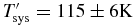 $T_{\text{sys}}^\prime = 115\pm 6 \text{K}$
and η = 0.72 ± 0.05.
$T_{\text{sys}}^\prime = 115\pm 6 \text{K}$
and η = 0.72 ± 0.05.

Figure 5. Results of a drift-scan of the Galactic plane conducted on 2015 July 25 with antennas pointed at the southern meridian at zenith angle 5.4°; these results are for a boresight beam on AK15 and were generated from an 8-MHz bandwidth centred at 1396 MHz. The left panel shows the variation of SEFD during the scan (blue), and the flux-density equivalent of the fitted sky model (red); the abscissa is labelled with the Right Ascension at beam centre. The right panel shows the variation of SEFD with the 1.4-GHz sky brightness temperature as determined from an all-sky Parkes continuum image (Calabretta et al. Reference Calabretta, Staveley-Smith and Barnes2014). The red line shows the linear fit whose intercept and slope give
 $\text{SEFD}(T_{\text{sky}} = 0)$
and
$\text{SEFD}(T_{\text{sky}} = 0)$
and
 $\frac{2k}{A\eta }$
, respectively.
$\frac{2k}{A\eta }$
, respectively.
7.1.2. Field-of-view
To determine the variation of sensitivity across the Mark I PAF field-of-view, we have measured the SEFD in each of a set of nine beams arranged linearly and spanning the expected field-of-view. For the
 $i{\text{th}}$
beam, the relative sensitivity is calculated as
$i{\text{th}}$
beam, the relative sensitivity is calculated as
 $\text{SEFD}_0/\text{SEFD}_i$
where
$\text{SEFD}_0/\text{SEFD}_i$
where
 $\text{SEFD}_0$
is measured on the boresight beam. The resulting profile (Figure 6) resembles that expected from electromagnetic modelling (Bunton & Hay Reference Bunton and Hay2010).
$\text{SEFD}_0$
is measured on the boresight beam. The resulting profile (Figure 6) resembles that expected from electromagnetic modelling (Bunton & Hay Reference Bunton and Hay2010).

Figure 6. The sensitivity of beams arranged in a line across the PAF field-of-view, relative to that of the boresight beam. The measurement was made from a single observation of PKS B1934–638 with each beam in antennas AK03, AK08, and AK15. SEFD values were computed for the band 960–980 MHz from the visibilities on each baseline in both X and Y polarisations; the mean of the quantity
 $\text{SEFD}_0/\text{SEFD}_i$
for each beam i is plotted. The error bars indicate the variation across the three baselines.
$\text{SEFD}_0/\text{SEFD}_i$
for each beam i is plotted. The error bars indicate the variation across the three baselines.
7.2. Beams
7.2.1. Characteristics of maximum sensitivity beams
Figure 7 shows holographic maps of the BETA beams. Noteworthy features of the beams include strong four-fold symmetry (particularly in the side-lobes) associated with the structure that supports the PAF at the antenna focus, and elongation of the most offset beams due to coma distortion. Because the antennas have a relatively small 12-m aperture and must support a PAF weighing approximately 300 kg, the PAF itself and its mechanical supporting structure create a significant aperture blockage that clearly impacts the shape of the maximum sensitivity beams. On boresight, the power in the side-lobes is roughly 15 dB below the peak power level in the primary beam in the worst case, but up to 10 dB below this level in different quadrants (see Figure 8). The side-lobes become more prominent for beams offset from centre.

Figure 7. Holographic beam maps, each 8° × 8°, for a single 1-MHz channel with a frequency of 916 MHz. The nine panels show nine different beams, representing a square footprint with pitch 1.46°. The two polarisations have been combined to form Stokes I. Contours represent 1, 3, 6, 9, and 15 dB below the peak.

Figure 8. Slices through the map of the boresight beam shown in Figure 7. The black and cyan traces are crossed diagonal slices through the centre, yellow is a horizontal slice, and magenta is a vertical slice.
The beams formed in the X and Y polarisations are noticeably elliptical with major axes parallel to the plane of polarisation. To quantify this, and to explore the beam position and shape variation with wavelength, we have analysed a set of central, boresight beams formed and measured on five of the antennas over the 711.5–1015.5-MHz range (the sixth was used as reference in the holographic measurement). Although the holography naturally measures the shape of an antenna’s voltage response, we squared the measured amplitudes to assess the pattern of response to incident power. There are 304 boresight beams formed on each antenna: one for each coarse frequency channel. We characterised each with an ellipse fitted to its half-power level, the parameters of the ellipse giving the beam position relative to expectations and the lengths of the beam major and minor axes.
We conducted this analysis on two sets of boresight beam, formed on 2015 May 08 and on 2015 May 12. We found similar results for both, although the holography observations of the first formed set suffered more from RFI. In the following paragraphs, we give the results for the second set of beams.
Beam positions
Figure 9 shows, for each antenna-polarisation combination, beam positions relative to their mean position, and scaled by λ/D. Also shown is the position of each Y beam relative to the X beam of the same frequency. The median positions were subtracted before plotting the X and Y values because they include contributions from antenna pointing (irrelevant for this discussion) at the time of the holography measurements. From examination of the statistics of the measured beam positions, we estimate the uncertainty (1σ) in position determination to be approximately 0.0005λ/D, a value consistent with the strength of the reference source and the SEFD. For each antenna, approximately 10% of beam fits give discrepant values that we attribute to the effect of intermittent RFI or other errors at the time of the holography; these values fall outside the position ranges shown in Figure 9. Amongst the remainder, significant and systematic position variations are evident, with the behaviour being antenna dependent.

Figure 9. The left and centre columns show X and Y beam positions after subtraction of their median (marked by the open circle) across the 711.5–1015.5-MHz band, for five of the BETA antennas. The right column shows the positions of the Y relative to the X beam at each frequency.
On most antennas, beams are clustered close to their median position with a dispersion of about ten times the measurement uncertainty. For this set of beams, antenna AK09 is an exception with a pronounced wavelength-dependent position. In this display, any systematic position error common to all spectral channels is hidden by the median subtraction. An indication of typical systematic shifts is given in the third column of the figure that shows the position difference between polarisations; over the five antennas, the median position differences between X and Y beams range from 0.004 to 0.021 λ/D. At the centre of the observing band, these offsets are 0.4–2.1 arcmin, comparable to or larger than measurable antenna pointing errors (see Section 3.2).
Beam size and shape
The beam widths and ellipticity, as determined from fitted half power levels, are summarised in Figure 10. The X and Y polarised beams are elliptical with major axes parallel to the plane of polarisation. The ellipticity is wavelength-dependent. The total intensity beams (sum of X and Y beams) are also mildly elliptical, but their widths are proportional to wavelength. The figure shows a 5–10% variation of beam widths amongst the five measured antennas. Also evident is a 25-MHz periodicity in beam width, which is the expected periodicity of a standing wave in the 6-m cavity between focus and vertex.

Figure 10. Beam shapes for X and Y polarisations and their sum (top, middle, bottom). The major and minor axes of best-fit ellipses at beam half-power level are given in units of λ/D. The heavy lines give the mean values over five of the six BETA antennas; the sixth, AK01 was the reference antenna in the holography measurements. The grey bands indicate the extreme values over the five antennas. Note the 25-MHz periodicity in beam width, which is referred to in the text.
Together, the antenna and polarisation dependencies of beam position and size produce a fractional dispersion in antenna gains at the beam half-power points of approximately 10%.
Modelling the beams
The measured beams were formed using the maxSNR method. This method gives high weight to PAF elements in the brighter parts of the focussed pattern, but it also down-weights elements that have low gain or high noise, wherever they fall in the pattern. Therefore, although the field distribution on the PAF may be well described by optical theory, the actual beam formed will also depend upon the electrical characteristics of the individual elements in the PAF. The variation in beam position and shape illustrated in Figures 9 and 10 is, in part at least, a consequence of the variation in behaviour of the PAF elements.
Ellipticity of the polarised beams is expected. Minnett & Thomas (Reference Minnett and Thomas1968) have modelled the fields in the focal plane of a circular paraboloidal reflector, uniformly illuminated by a linearly polarised wave. They compute a field distribution that resembles the classic Airy pattern with a central lobe and concentric lobes of alternating field direction, but which is elliptical with a size and ellipticity dependent on the focal ratio f/D. The model as presented by Minnett & Thomas predicts the major and minor axes (a, b), at half-power, of the polarised beams to be (1.11, 1.02)λ/D, and a circular total-intensity beam of width 1.06λ/D, all smaller than the measured dimensions shown in Figure 10. We have extended this model by modifying the illumination to include a circular central blockage and a tapering function T(θ) = cos(aθ), where θ is the angular displacement from the vertex as viewed from the focus, and the parameter a determines the amount of tapering. We find that the size of the total intensity beam (ignoring its small ellipticity) can be accommodated by the model with a taper function T that reduces the illumination at the edge of the antenna to about 44% of its central value. Taper of that magnitude corresponds to an aperture efficiency of η = 0.70, similar to the measured value given in Section 7.1.1.
We emphasise that this simple model for beam size and shape does not account for asymmetries in the optics, notably the tetrapod support structure for the focal equipment. It assumes frequency-independent and circularly symmetric radiation patterns for the PAF elements, almost certainly not realised. Nor does it include effects of multi-path reflections.
Analysis of the observed off-axis coma distortion is beyond the scope of this paper.
7.2.2. Stability of formed beams
Any variation in time of PAF element characteristics or signal path from PAF to beamformer has the potential to also cause the beam shapes to change with time. During the early operation of BETA, it became clear that beam performance was declining over the days following the determination of beam weights. The major factor leading to invalidation of a set of weights turned out to be random delays of a few digital sampling intervals (1.3 ns) being introduced with every power cycle of the antenna pedestal hardware. This was sufficient to significantly degrade the quality of a formed beam.
We adopted a two-fold solution to this problem (which will be fixed in firmware when the next generation of ASKAP hardware is deployed). First, we determined a new set of maximum sensitivity beams after every major power outage. Second, we took ACM measurements of a standard reference field (a region centred on the South celestial pole) at regular intervals, which was used to make a measurement of delays introduced per PAF element with respect to a reference epoch. If delays were detected, they were compensated with an additional element-based correction to the digital delay line.
7.3. Polarimetry
A series of observations were made in the 711.5–1015.5-MHz band to assess the polarimetric performance of the BETA antennas. Two sources were chosen for the tests: PKS B1934–638, the standard southern flux-density calibrator known to have no detectable linearly polarised emission, and 3C138, a well characterised and strongly polarised source. These sources were observed on the optical axis of the antennas; PKS B1934–638 was also observed off-axis, and again on-axis but through eight different offset beams. For the tests of a beam on the optical axis, observations were done both with the roll axis tracking (i.e. the normal BETA mode) and with the roll axis locked (i.e. BETA antennas behaving as classical alt-az antennas with parallactic angle rotation needing to be accounted for in the polarimetric solutions). The two approaches gave consistent results.
For polarimetric work the phase difference between the X and Y polarisation channels must be known. Whereas some instruments measure this phase difference using a noise injection system, such a system was not available with BETA (it will be included in the full ASKAP system). For a significantly polarised source, such as 3C138, XY phase differences can be determined as part of the source observation. However, for an unpolarised source such as PKS B1934–638, extra steps need to be taken to make it possible to determine XY phase difference. With BETA observations of PKS B1934–638, the approach used was to intentionally misalign the roll axis on one antenna (AK03) by 5°. This puts sufficient, known, signal into the XY correlations of baselines with this antenna to be able to determine the XY phase. This approach is somewhat akin to the ‘cross-dipoles’ approach used previously at the Westerbork telescope (Weiler Reference Weiler1973). It was verified that the two approaches to determining XY phase produce consistent results.
On-axis, BETA is polarimetrically pure. Polarisation leakage between X and Y channels was measured on both PKS B1934–638 and 3C138 and found, on most antennas, to be small ( < 0.5%) and frequency independent. The leakages were stable over months. The only significant departure from zero leakage was a clear positive–negative asymmetry between the real parts of the X and Y feeds in some antennas, characteristic of a rotation of the whole PAF. These antennas appear to have a small rotational misalignment about their roll axis; the largest error observed was ~ 2° in AK15. Once identified, such misalignments are easily corrected.
For polarimetric measurements of 3C138, account must be taken of the Faraday Rotation caused by the ionosphere. Ionospheric Faraday Rotation is a time-varying, wavelength-dependent rotation of the plane of polarisation (an advantage of using an unpolarised test source such as PKS B1934–638 is that the observation is not affected by the ionosphere). For 3C138 observations, the ionFR package (Sotomayor-Beltran et al. Reference Sotomayor-Beltran2013) was used with global GPS ionospheric soundings to estimate the ionospheric rotation measure as a function of time during the observation. After accounting for the ionospheric rotation, the measured PA and intrinsic rotation measure of 3C138’s polarised emission was consistent with previously existing results.
Leakages measured with the source off-axis (placed at the 65% level on the axial primary beam) were similarly small, apart from ~ 1% leakage of the real parts of X and Y signals near 1 GHz.
The main source of polarisation inaccuracy in BETA is the a priori unknown beam shape. This is particularly acute for the Stokes U parameter, formed from the difference between XX and YY visibilitiesFootnote 3 . The analysis of a typical example of formed beams described in Section 7.2 shows dispersion in the shapes of X and Y beams, and in their relative positions. These both impair the polarisation performance, most severely for sources away from beam centres. Little detailed analysis has been done on off-axis beams and the implications of their properties on polarimetric performance.
More information on polarimetric characterisation of BETA is given by Sault (Reference Sault2014 and Reference Sault2015).
Because of the presence of polarised sources in the sky, the best imaging results, even in total intensity (Stokes I), require attention to wide-field polarimetric corrections. If all antennas can be treated as having identical polarimetric responses that are independent of time, the polarimetric correction can be relatively simple because the use of the roll axis means that the polarimetric response does not vary throughout the observation as parallactic angle changes. The instrumental polarimetric response of a source is thus independent of time and baseline, and can be corrected in the image domain after deconvolution. The correction would be implemented by a Mueller matrix, the coefficients of which would be dependent on a pixel’s location relative to the pointing centre. This is analogous to primary beam correction being performed in the image domain. However, ionospheric Faraday rotation correction is a complication of such a scheme because, in general, the ionospheric Faraday rotation will vary significantly over the course of an observation. Correcting for ionospheric Faraday rotation should be done before the imaging of the Stokes parameters, otherwise a time-varying rotation between Stokes Q and U will be introduced. Approaches that combine snapshot images are being investigated for implementation in ASKAPsoft.
7.4. Image quality
Many imaging experiments have been conducted with BETA. All have used beams formed with the maxSNR method. A range of fields have been imaged, with various sizes, declinations, and complexity. Several fields, such as the Apus field centred near (RA, Dec)
 $_{{\text J2000}}$
= (
$_{{\text J2000}}$
= (
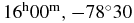 $16^{{\text h}}00^{{\text m}},-78\hbox{$^\circ $}30$
), and the field containing calibration source PKS B1934–638, have been used as test fields and have been imaged many times during the commissioning period to allow assessment of changes made to beamforming and calibration techniques. Images of four fields have been published (see Table 2), and we draw upon the analysis of those images for our characterisation of BETA’s imaging performance below.
$16^{{\text h}}00^{{\text m}},-78\hbox{$^\circ $}30$
), and the field containing calibration source PKS B1934–638, have been used as test fields and have been imaged many times during the commissioning period to allow assessment of changes made to beamforming and calibration techniques. Images of four fields have been published (see Table 2), and we draw upon the analysis of those images for our characterisation of BETA’s imaging performance below.
Table 2. Fields with published images made with BETA.
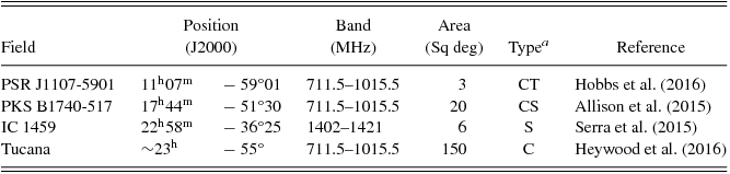
a C: Continuum; S: Spectral; T: Time series.
7.4.1. Sensitivity
The RMS brightness in spectral images with channel bandwidth of 18.5 kHz is consistent with the measured SEFD at 1.4 GHz of 4 000 Jy (see Figure 4). However, the RMS brightness in continuum exceeds that expected from the SEFD by a factor of about three. Heywood et al. (Reference Heywood2016) attribute this to the incomplete deconvolution that is inevitable with automated reduction pipelines in the presence of the significant sidelobe confusion typical of BETA continuum images.
7.4.2. Photometry
Photometric performance has been assessed by comparing source catalogues constructed from BETA images with catalogues from other instruments: the SUMSS catalogue (Mauch et al. Reference Mauch, Murphy, Buttery, Curran, Hunstead, Piestrzynski, Robertson and Sadler2003) for the 711.5–1015.5-MHz image of the Tucana field, and the VLA NVSS catalogue (Condon et al. Reference Condon, Cotton, Greisen, Yin, Perley, Taylor and Broderick1998) for the 1.4-GHz image of IC 1459. In both cases, systematic differences in the flux-density scales were observed. Flux densities of sources in the IC 1459 image exceed those of the corresponding NVSS sources by a factor of about 1.07. Apparent flux densities of sources in the Tucana image differ from their counterparts in the SUMSS catalogue in a flux-density dependent way: The weakest sources appear fainter in the BETA image, whereas the strongest sources appear brighter; the ratio varies smoothly from ~ 0.84 to ~ 1.04 over the full flux-density range. Heywood et al. (Reference Heywood2016) discuss the possible causes of this discrepancy. By selecting the subset of sources that are unresolved in the SUMSS catalogue, they exclude bias caused by the different PSFs of the two instruments. Both Serra et al. (Reference Serra2015) and Heywood et al. (Reference Heywood2016) suggest that limitations in our knowledge of beam shape can contribute to the observed bias.
We note that flux-scale differences amongst catalogues constructed with different instruments or techniques are not unsual—see Allison, Sadler, & Meekin (Reference Allison, Sadler and Meekin2014) for an example similar to the BETA-SUMSS comparison. In general, precise photometry with radio interferometers is difficult. There are many contributing factors, including statistical effects (e.g. the Eddington bias), differences in spatial frequency coverage, and the complex interactions between deconvolution and self-calibration that are invariably instrument-specific. There is no evidence for the observed flux-scale discrepancies indicate a fundamental limitation of ASKAP. In future, the increase in numbers of antennas and improved knowledge and control of primary beam shape are likely to improve photometric performance, but ASKAP will remain subject to all the factors common to other radio telescopes.
7.4.3. Astrometry
Heywood et al. (Reference Heywood2016) analysed BETA’s astrometric precision and accuracy by comparing apparent source positions in the Tucana image with those of the SUMSS catalogue. They separated the differences into a random statistical component and a systematic shift, identified as the mean offset in RA and Dec for each of the three epochs of the Tucana observation. Once the systematic offsets are subtracted, the distribution of residual errors is similar for all three epochs and broadly consistent with the size of the synthesised beam (70 arcsec × 60 arcsec) and the signal-to-noise ratios of the sources in the BETA image. Heywood et al. (Reference Heywood2016) report the 1σ uncertainties in (RA, Dec) to be (3.6, 4.5) arcsec, averaged over the three epochs.
The systematic offsets were different for each epoch; the largest had a magnitude of 12.7 arcsec. Astrometric accuracy of a radio interferometer is usually achieved through calibration of interferometer phases with observations of a source with well-known position and that is close to the observed field. BETA’s imaging observations were calibrated with a single observation of PKS B1934–638 before or after the 12-h synthesis. The systematic position errors observed can be understood in terms of small imperfections in the telescope’s delay (antenna position) model and the transfer of phase reference from a calibrator 25° distant, and in likely electronic drifts in the PAF amplifiers.
In the future, a model of the sky, a ‘Global Sky Model’ (Cornwell et al. Reference Cornwell, Humphreys, Lenc, Voronkov and Whiting2011), will be developed and used to calibrate antenna gains. Inclusion of astrometric calibrators in this model, with a sky density sufficient for at least one to appear in every ASKAP field, will allow all observations to be tied to an astrometric reference frame.
7.4.4. Response to complex source structure
Images of complex fields have been made, such as the Large Magellanic Cloud (LMC) shown in Figure 11, the bright radio galaxy NGC 1316 in Fornax, and the region of the Galactic plane close to PSR J1107-5901 (Hobbs et al. Reference Hobbs2016). Figure 11 shows an image of the LMC made in the 711.5–1015.5-MHz band with visibilities from the 37-m baseline excluded. This image was produced using ASKAPsoft, following a series of steps similar to those listed in Section 6. In this case, data were preconditioned using a Wiener filter (see Cornwell et al. Reference Cornwell, Humphreys, Lenc, Voronkov and Whiting2011 for an explanation of methods used in ASKAPsoft) to effect a traditional robust weighting with parameter r = −0.5 (Briggs Reference Briggs1995). The image was deconvolved using a multiscale procedure: ASKAPsoft’s ‘BasisfunctionMFS’ algorithm with scales of 0, 3, 10, and 30 pixels. The complex extended radio emission associated with the star-forming region 30 Doradus (near 05 h 38 m , −69°06′) is not well represented in this image: BETA’s shortest baselines (37, 144, 176 m) give inadequate sampling of the inner part of the (u, v) plane for reconstructing structures of this scale, as discussed by Serra et al. (Reference Serra2015).

Figure 11. Image of the Large Magellanic Cloud in the 711.5–1015.5-MHz band. The 11-h observation was made with eight pointings of a square nine-beam footprint: a pair of 2 × 2 grids, offset from each other to achieve the interleaving scheme illustrated in Figure 3. The eight pointings were observed cyclically, for 5 min in each cycle giving an integration time of 82 min on each pointing. The deconvolved image was restored with a 60 arcsec × 60 arcsec beam, and the brightness scale on the right is in units of Jy beam−1. Note the image artifacts associated with the bright and extended H ii region 30 Doradus near (RA, Dec) = (05 h 38 m , −69°06′). This image was produced with an automated askapsoft pipeline.
7.4.5. Beam variations
All imaging observations with BETA have been made with maxSNR beams, whose typical characteristics we present in Section 7.2. Continuum images made with BETA do not achieve the sensitivity expected from thermal noise considerations. Heywood et al. (Reference Heywood2016) attribute this sensitivity loss to calibration biases and incomplete deconvolution that are difficult to avoid with a small array like BETA. Another contributor to sensitivity loss is the dispersion in beam position and size reported in Section 7.2. Ideally, the gain of the
 $i{{\text th}}$
antenna (for a given polarisation) could be written as functions of time t, frequency ν, and direction (θ, ϕ):
$i{{\text th}}$
antenna (for a given polarisation) could be written as functions of time t, frequency ν, and direction (θ, ϕ):
 $$\begin{equation*}
g_i(\nu ,t,\theta ,\phi ) = A(\nu ,\theta ,\phi ) b_i(\nu ) f_i(t),
\end{equation*}$$
$$\begin{equation*}
g_i(\nu ,t,\theta ,\phi ) = A(\nu ,\theta ,\phi ) b_i(\nu ) f_i(t),
\end{equation*}$$
where the bandpass bi and the normalised antenna reception pattern A are both time-invariant and A is the same for all antennas in the array with its angular scaling inversely proportional to frequency. Accounting for variation in A, with time, polarisation or antenna is difficult and expensive in computation time, and has not been implemented in any of the automated BETA processing software. Uncorrected, variation of A will decrease the dynamic range of the image.
8 SUMMARY AND CONCLUSIONS
BETA has been used to develop methods for operating, calibrating, and making astronomical observations with a synthesis telescope equipped with PAFs. The focus of the work has been learning how to electronically form beams, how to measure and arrange beams, and how to modify the familiar steps of calibration and synthesis imaging to make the best use of formed beams.
A range of astronomical imaging and spectral detection experiments have been conducted in support of commissioning, and to take advantage of BETA’s wide field-of-view and its access to the relatively clean part of the radio spectrum from 0.7 to 1.2 GHz. The scientific results from these are summarised in Section 2.4.
We began in the introduction (Section 1) with some questions about the future success of ASKAP for which we sought answers through experiment with BETA. Several of the questions have been answered positively; for others, the BETA experience has provided partial answers with good indications of the remaining problems to be solved. We conclude by listing three critical challenges to be met in the operation of ASKAP:
Reliability. Large-area surveys conducted over months or years demand a high level of stability and reliability in the telescope. For much of its operation, BETA’s reliability was sufficient to yield uniform results for modest-sized surveys. ASKAP will have many more components (antennas, beamformers) and modes of operation and its surveys will be much larger. These will all place much higher demands on reliability than were necessary for BETA.
Beam shape. We have described the maxSNR beam forming methods used with BETA and assessed metrics of the resulting beams. We continue to develop alternate methods that give control over beam shape; in spite of promising progress, more work is required to prove these methods and to make them operational. Successfully constraining beam shape is important for success of several of ASKAP’s SSPs, particularly so for wide-field polarimetry.
Gain stabilisation. BETA had no reference noise signal for measuring receiver (PAF element) gains. However, for the observations made with BETA, gains were stable enough to allow synthesis imaging with a single measurement, per beam, of a standard source for bandpass calibration, and with minor corrections to antenna gain variations during the synthesis using self-calibration with source models of the field. Daily (or more frequent) observations for calibrating each of ASKAP’s 36 beams will significantly degrade observing efficiency, so methods for using the on-dish-calibration system for measuring PAF element gains will need to be developed.
ACKNOWLEDGEMENTS
The Australian SKA Pathfinder is part of the Australia Telescope National Facility which is funded by the Commonwealth of Australia for operation as a National Facility managed by CSIRO. This scientific work uses data obtained from the Murchison Radio-astronomy Observatory (MRO), which is jointly funded by the Commonwealth Government of Australia and State Government of Western Australia. The MRO is managed by the CSIRO, who also provide operational support to ASKAP. We acknowledge the Wajarri Yamatji people as the traditional owners of the Observatory site.
Parts of this research were conducted by the Australian Research Council Centre of Excellence for All-sky Astrophysics (CAASTRO), through project number CE110001020.
This work was supported by resources provided by the Pawsey Supercomputing Centre with funding from the Australian Government and the Government of Western Australia.


