1. INTRODUCTION
In recent years, there has been a lot of research progress achieved on generation of runaway electrons (RAEs) in laboratory gas discharges at increased pressure (see Levko et al., Reference Levko, Krasik and Tarasenko2012b). Most attention in this field in the last decade was focused on the parameters and properties of RAEs in atmospheric air and on the mechanism of their generation. New experimental data were obtained due to the development of measuring equipment and technologies. The runaway electron beams downstream of a foil anode was proposed to term a super-short avalanche electron beam or shortly SAEB (Tarasenko et al., Reference Tarasenko, Orlovskii and Shunailov2003). It is this term that we use throughout the paper.
Among the important results obtained since 2003, the most significant achievement is that the number of RAEs downstream of the anode measured in atmospheric air substantially increases. In the previous work (Tarasova et al., Reference Tarasova, Khudyakova, Loiko and Tsukerman1974), the number of RAEs was 109, and subsequent works of other scientific groups failed to increase this parameter (Babich, Reference Babich2003; Babich & Loiko, Reference Babich and Loiko2010). However, in 2003, about a 10-fold increase in the number of RAEs and amplitude of the beam current was observed by the Institute of High Current Electronics (IHCE) (Alekseev et al., Reference Alekseev, Orlovskii and Tarasenko2003; Tarasenko et al., Reference Tarasenko, Orlovskii and Shunailov2003). Note that the main data on the generation of RAEs and X-rays obtained until 2003 are reported (Babich, Reference Babich2003), and analysis of various RAE measuring techniques, including those used by IHCE, is given elsewhere (Kostyrya et al., Reference Kostyrya, Baksht and Tarasenko2010; Reference Kostyrya, Rybka and Tarasenko2012; Tarasenko et al., Reference Tarasenko, Rybka, Baksht, Kostyrya and Lomaev2007; Reference Tarasenko, Baksht, Burachenko, Kostyrya, Lomaev and Rybka2008a; Reference Tarasenko, Rybka, Baksht, Kostyrya and Lomaev2008b; Reference Tarasenko, Baksht, Burachenko, Kostyrya, Lomaev and Rybka2008c; Reference Tarasenko, Rybka, Burachenko, Lomaev and Balzovsky2012b; Tarasenko, Reference Tarasenko2011).
The generation of SAEBs with maximum amplitudes requires numerous electron avalanches in the gap which, when overlapped, form a dense diffuse plasma. The front of this plasma crosses the gap with a high velocity from the cathode to the anode, generating a SAEB between the dense plasma front and the anode. In atmospheric air, the highest SAEB amplitude until now was obtained on the SLEP-150 generator (Tarasenko et al., Reference Tarasenko, Kostyrya, Baksht and Rybka2011) and was about 100 A downstream of the Al foil anode (Kostyrya et al., Reference Kostyrya, Rybka and Tarasenko2012). The full width on the half maximum (FWHM) of the SAEB pulse (SAEB width) was about 100 ps and the number of RAEs in the beam was more than 6 × 10¹⁰. Note that the SAEB amplitude and the number of RAEs mentioned above were not the limit and could be increased by decreasing the pulse rise time (Tarasova et al., Reference Tarasova, Khudyakova, Loiko and Tsukerman1974; Tarasenko et al., Reference Tarasenko, Baksht, Burachenko, Kostyrya, Lomaev and Rybka2008c) as well as by optimizing the cathode material (Zhang et al., Reference Zhang, Tarasenko, Shao, Baksht, Burachenko, Yan and Kostyray2013) and cathode design (Kostyrya et al., Reference Kostyrya, Baksht and Tarasenko2010; Reference Kostyrya, Rybka and Tarasenko2012). The effect of the cathode material and design on the SAEB amplitude was also studied in other works (Tarasenko, Reference Tarasenko2011; Tarasenko et al., Reference Tarasenko, Skakun, Kostyrya, Alekseev and Orlovskii2004; Reference Tarasenko, Shpak, Shunailov and Kostyrya2005; Reference Tarasenko, Baksht, Burachenko, Kostyrya, Lomaev and Rybka2008a; Reference Tarasenko, Baksht, Burachenko, Kostyrya, Lomaev and Rybka2008c; Reference Tarasenko, Baksht, Burachenko, Kostyrya and Rybka2013b). In nitrogen, hydrogen, and helium at decreased pressures, the SAEB amplitude from the entire anode foil on the SLEP-150 generator reached about 500 A with a FWHM of the beam current of about 100 ps (Tarasenko et al., Reference Tarasenko, Baksht, Burachenko, Kostyrya, Lomaev and Sorokin2010). Images of RAEs and/or X-rays on films were obtained in nitrogen at a pressure up to 4 MPa (Ivanov, Reference Ivanov2013).
The SAEB width (about 100 ps) that was actually measured in atmospheric air was first reported in the paper by Tarasenko et al. (Reference Tarasenko, Shpak, Shunailov and Kostyrya2005). In later experiments, it was shown that the SAEB width depended on the anode diaphragm diameter, inter-electrode gap, kind of gas and gas pressure (Baksht et al., Reference Baksht, Lomaev, Rybka and Tarasenko2006; Reference Baksht, Burachenko, Erofeev, Lomaev, Rybka, Sorokin and Tarasenko2008; Kostyrya et al., Reference Kostyrya, Rybka and Tarasenko2012; Tarasenko, Reference Tarasenko2011; Tarasenko et al., Reference Tarasenko, Baksht, Burachenko, Kostyrya, Lomaev and Rybka2008a; Reference Tarasenko, Rybka, Baksht, Kostyrya and Lomaev2008b; Reference Tarasenko, Baksht, Burachenko, Kostyrya, Lomaev and Sorokin2010; Reference Tarasenko, Erofeev, Lomaev, Sorokin and Rybka2012a; Reference Tarasenko, Rybka, Burachenko, Lomaev and Balzovsky2012b). When the SAEB extracted from a diaphragm whose diameter was 1 mm, SAEB pulses with a FWHM of about 25 ps were obtained (Tarasenko et al., Reference Tarasenko, Erofeev, Lomaev, Sorokin and Rybka2012a; Reference Tarasenko, Rybka, Burachenko, Lomaev and Balzovsky2012b). However, the SAEB width from the entire anode foil surface in atmospheric air was about 100 ps.
With a tubular cathode, the SAEB in atmospheric air was generated into a solid angle larger than 2π sr (Tarasenko et al., Reference Tarasenko, Baksht, Burachenko, Kostyrya, Lomaev and Rybka2008a; Reference Tarasenko, Baksht, Burachenko, Kostyrya, Lomaev and Rybka2008c), while with a grid cathode, the SAEB was detected in the direction opposite to the anode (Kostyrya et al., Reference Kostyrya, Rybka, Tarasenko, Kozyrev and Baksht2013). The X-ray exposure dose was 3 mR per pulse (Kostyrya et al., Reference Kostyrya, Rybka, Tarasenko, Kozyrev and Baksht2013).
The generation of RAEs was observed at high pulse repetition frequencies. In atmospheric air, the X-rays produced by RAEs in batches of 1500 pulses were detected at a frequency of up to 3 kHz (Tarasenko, Reference Tarasenko2006). In the repetitive pulse mode, the X-rays arose at a pulse repetition frequency of 1 kHz (Shao et al., Reference Shao, Tarasenko, Zhang, Baksht, Yan and Shut'ko2012a; Zhang et al., Reference Zhang, Shao, Yu, Niu, Yan and Zhou2010). In the pulse repetitive mode at decreased pressures of nitrogen and helium, the SAEB was measured by a collector at a frequency of 1 kHz (Erofeev et al., Reference Erofeev, Baksht, Tarasenko and Shut'ko2013). In atmospheric air, a dynamic capacitive current with amplitude of 4 kA was measured as the ionization wave front propagated in the gap (Shao et al., Reference Shao, Tarasenko, Zhang, Burachenko, Rybka, Kostyrya, Lomaev, Baksht and Yan2013).
The generation of RAEs is a fundamental phenomenon in gas discharge physics. However, relevant papers, including those cited above, focus mostly on the generation of RAE beams in atmospheric air (0.1 MPa) while the corresponding research on such generation in other gases is few. In particular, there are rather few data on the generation of RAE beams in SF6. Furthermore, sometimes these data are contradictory with each other.
The generation of SAEB in SF6 at atmospheric pressure was first reported by Babich and Loiko (Reference Babich and Loiko1991). The number of RAEs in SF6 was judged from the blackening of X-ray film and was estimated to be 108 electrons per pulse, which was about 10 times lower than that in atmospheric air. The width of the beam current pulse was measured by using a scintillator and a photomultiplier at a time resolution of no longer than 3.5 ns. The results that the RAE beam energy in SF6 was higher than that in air and that the beam generated in SF6 and air was mono-energetic with anomalous energy, in the authors' opinion (Babich & Loiko, Reference Babich and Loiko1991), were apparently dubious due to measurement errors. The anomalous energy of RAEs was higher than eU m (Babich & Loiko, Reference Babich and Loiko1985; Reference Babich and Loiko1991), and the U m here referred to the maximum over-voltage in the discharge. This error of estimation of the electron energy in air (Babich & Loiko, Reference Babich and Loiko1985) and SF6 (Babich & Loiko, Reference Babich and Loiko1991) and/or voltage across the gap as well as incorrect description of the generation mechanism of RAE beams was repeated in publications of this scientific group, including in the monograph (Babich, Reference Babich2003), within 20 years. However, as shown (Baksht et al., Reference Baksht, Burachenko, Kozhevnikov, Kozyrev, Kostyrya and Tarasenko2010; Tarasenko, Reference Tarasenko2011; Tarasenko et al., Reference Tarasenko, Shpak, Shunailov and Kostyrya2005; Reference Tarasenko, Rybka, Baksht, Kostyrya and Lomaev2007; Reference Tarasenko, Baksht, Burachenko, Kostyrya, Lomaev and Rybka2008a; Reference Tarasenko, Rybka, Baksht, Kostyrya and Lomaev2008b; Reference Tarasenko, Baksht, Burachenko, Kostyrya and Rybka2013b), the runaway electron beam downstream of the foil anode consisted of two or three groups of electrons of different energies and the number of electrons with anomalous energy was not more than 10% (Baksht et al., Reference Baksht, Burachenko, Kozhevnikov, Kozyrev, Kostyrya and Tarasenko2010). No RAEs with anomalous energy in atmospheric air were detected, like in the study by Mesyats et al. (Reference Mesyats, Reutova, Sharypov, Shpak, Shunailov and Yalandin2011), and the energy of RAEs was assumed not to exceed eU m under any conditions. All other things being equal, comparison of the energy of RAEs in SF6 and air demonstrated that the electron energy in air was higher than that in SF6, (Baksht et al., Reference Baksht, Burachenko, Erofeev, Lomaev, Rybka, Sorokin and Tarasenko2008).
A SAEB in SF6 at atmospheric pressure was measured for the first time with a collector at a sub-nanosecond time resolution (Baksht et al., Reference Baksht, Lomaev, Rybka and Tarasenko2006). It was shown that the FWHM of the beam current pulse in SF6 at a pressure of 0.1 MPa was about 100 ps. In their work, the RADAN-220 generator (Zagulov et al., Reference Zagulov, Kotov, Shpak, Yurike and Yalandin1989) was used and the SAEB was obtained in six different gases, including gases of high atomic number (Kr and Xe). However, no data were reported on the number of RAEs, SAEB amplitude, and the electron energy. The attempts to obtain a RAE beam in SF6 at a pressure of 0.1 MPa (Mesyats et al., Reference Mesyats, Korovin, Sharipov, Shpak, Shunailov and Yalandin2006) on the RADAN-303 generator (Yalandin & Shpak, Reference Yalandin and Shpak2001) were unsuccessful, which was presumably due to the non-optimal design of the gas diodes and longer rise time of the voltage pulse. However, a RAE beam in air in this work was obtained. The most detailed study of the generation of RAEs in SF6 at high time resolution (up to 90 ps) was conducted elsewhere (Baksht et al., Reference Baksht, Burachenko, Erofeev, Lomaev, Rybka, Sorokin and Tarasenko2008). The SAEB was obtained at SF6 at pressures of up to 0.2 MPa and it was shown that the SAEB pulse width depended on the pressure of SF6 and the amplitude of voltage pulse.
Note that there is another discrepancy in the research data on nanosecond-pulse discharges in SF6. According to the simulation results on the conductivity in SF6 and nitrogen where RAE was generated (Levko et al., Reference Levko, Gurovich and Krasik2012a) the plasma resistance within the first nanosecond after the breakdown in a SF6-filled gap at atmospheric pressure was two times lower than that in nitrogen. It was different from the experimental studies (Baksht et al., Reference Baksht, Burachenko, Kostyrya, Lomaev, Rybka, Shulepov and Tarasenko2009; Tarasenko, Reference Tarasenko2001), which pointed out the plasma resistance at breakdowns in SF6 and SF6-nitrogen mixtures was higher than that in nitrogen.
Taking into the consideration that the discharges in SF6 are not only for scientific interest, but has a great practical application value, because SF6 is widely used as an insulator in high-voltage devices (Bortnik, Reference Bortnik1998) and also as one of the components in chemical gas lasers (Gross & Bott, Reference Gross and Bott1976), the present study continues the research (Baksht et al., Reference Baksht, Lomaev, Rybka and Tarasenko2006; Reference Baksht, Burachenko, Erofeev, Lomaev, Rybka, Sorokin and Tarasenko2008). The objective of the study is the characteristics of SAEB generation in SF6 and, for comparison, in air and other gases under the same experimental conditions. This paper also reports on the measurements of the ionization wave front velocity in the gap at a time resolution up to 10 ps.
2. EXPERIMENTAL SETUP AND MEASUREMENT
Experiments were performed on two setups at different voltage pulse rise times. Unlike the previous works, one of the setups (setup 1) was particularly designed for studying the discharges and RAE generation in SF6 and made it possible to measure several relevant parameters simultaneously. Thus, setup 1 allowed us to measure the voltage across the discharge gap, current through the gap, SAEB, and radiation from different gap regions in a single pulse. Moreover, the voltage pulse polarity of RADAN-220 generator in setup 1 could be both negative and positive.
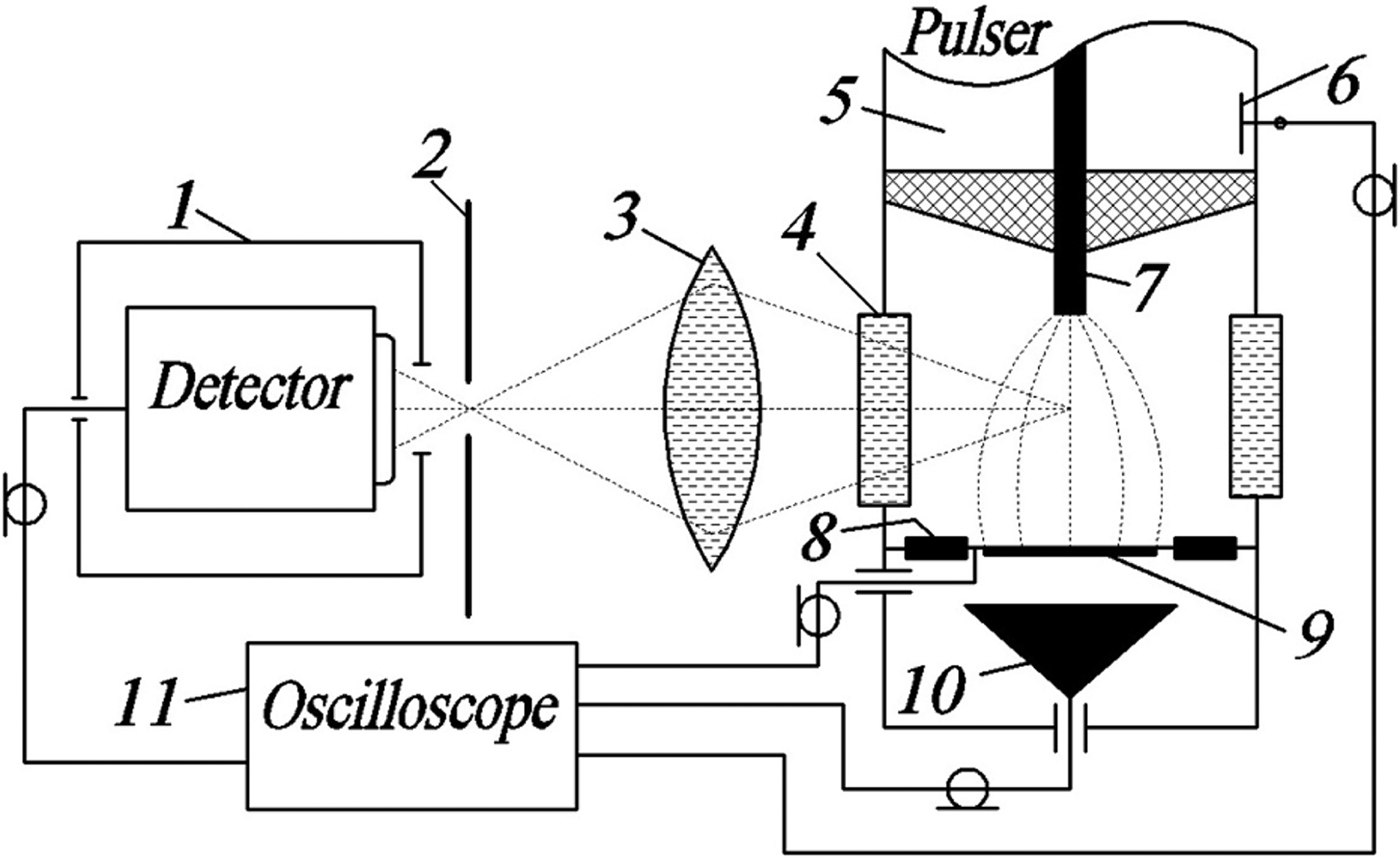
The discharge chamber and measuring system are shown in Figure 1. The voltage pulse produced by the RADAN-220 generator was applied through a short transmission line (5) to a tubular electrode with small curvature radius (7). This potential electrode (7) was made by rolling a 100-μm-thick stainless steel foil into a tube with a diameter of 6 mm. The grounded plane electrode (9) was located at a distance of 8, 10, or 13 mm from the bottom surface of the potential electrode. The voltage was measured by a capacitive divider (6) located at the end of the transmission line (5). The generator was connected with the gap via the short transmission line (5) whose wave impedance was several times higher than that of the RADAN-220 generator, making it possible to increase the voltage pulse amplitude in the gap to about 340 kV. The voltage pulse duration at a matched load was about 2 ns, and the pulse rise time in the transmission line was about 0.5 ns. The discharge current was measured by a shunt (8) composed of chip resistors. The chip resistors were connected in series with the plane electrode (9) and were uniformly located at its circumference. The SAEB was measured by a collector (10) and was measured simultaneously with the discharge current and voltage pulse in the gap with negative polarity of the voltage pulse. For the measurement of SAEB in a gap of 13 mm, the anode (9) was made of AlMg foil whose diameter was 1 cm and thickness was 50 µm and was placed on a metal grid whose transparency was 14%. The collector (10) was located downstream of the foil anode. For the measurement of SAEB in gaps of 8 and 10 mm, the anode was made of either 40-μm-thick AlBe foil or 10-μm-thick Al foil, both with a diameter of 1 cm. The anode from Al foil was placed on a metal grid whose transparency was 64%. Note that the study was not aimed at measuring the current downstream of the entire anode surface with minimum beam current loss at the support grid and maximum SAEB amplitude. The discharge chamber was filled with SF6, SF6 mixture with 2.5% of nitrogen, air, argon, krypton, or nitrogen. Air, argon, krypton, and nitrogen were used in comparative experiments in order to estimate the number of electrons in the SAEB and investigate the mechanism of SAEB generation. The discharge chamber was pumped with a forevacuum pump. The pressures of gases ranged from 0.05 to 0.3 MPa.

Fig. 1. Block-diagram of experimental setup 1: 1 = photodetector PD025 in metal box; 2 = screen with slit; 3 = lens; 4 = side window; 5 = transmission line of RADAN-220 generator; 6 = capacitive voltage divider; 7 = high voltage electrode; 8 = current shunt; 9 = ground electrode made of thin foil; 10 = collector; 11 = oscilloscope.
The optical radiation from different discharge regions was extracted through a side window (4) and was transmitted by a lens (3) to a photodiode located in a metal box (1). Upstream of the photodiode, there was a shield (2) with a 1-mm-width slit. On the slit plane, a magnified image of part of the gap was formed; the magnification ratio was 2:1. When the plasma filled this region, the photodetector recorded the radiation from this region. The spatial resolution of the system for measuring the radiation from each region of the discharge gap was about 1 mm in the direction of the longitudinal gap axis. The radiation was measured in the regions near the cathode and anode. Signals from the capacitive voltage divider, shunt, collector, and photodiode were transmitted to a Tektronix DPO70604 oscilloscope (6 GHz, 25 GS/s). The measuring elements were connected to the oscilloscope via RadioLab 5D-FB PEEG coaxial pulse cables with standard N-type connectors and Barth Electronics 142-NM attenuators with a bandwidth up to 30 GHz. Note that the SAEB parameters and spatial discharge images in air and nitrogen at negative polarity of voltage pulse were investigated in detail earlier (Baksht et al., Reference Baksht, Burachenko, Kozhevnikov, Kozyrev, Kostyrya and Tarasenko2010; Kostyrya et al., Reference Kostyrya, Rybka and Tarasenko2012; Shao et al., 2012; Reference Shao, Tarasenko, Zhang, Burachenko, Rybka, Kostyrya, Lomaev, Baksht and Yan2013; Tarasenko, Reference Tarasenko2011; Tarasenko et al., Reference Tarasenko, Skakun, Kostyrya, Alekseev and Orlovskii2004; Reference Tarasenko, Shpak, Shunailov and Kostyrya2005; Reference Tarasenko, Rybka, Baksht, Kostyrya and Lomaev2007; Reference Tarasenko, Baksht, Burachenko, Kostyrya, Lomaev and Rybka2008a; Reference Tarasenko, Rybka, Baksht, Kostyrya and Lomaev2008b; Reference Tarasenko, Baksht, Burachenko, Kostyrya, Lomaev and Sorokin2010; Reference Tarasenko, Erofeev, Lomaev, Sorokin and Rybka2012a; Reference Tarasenko, Rybka, Burachenko, Lomaev and Balzovsky2012b; Zhang et al., Reference Zhang, Shao, Yu, Niu, Yan and Zhou2010; Reference Zhang, Tarasenko, Shao, Baksht, Burachenko, Yan and Kostyray2013; see also Mesyats et al., Reference Mesyats, Korovin, Sharipov, Shpak, Shunailov and Yalandin2006; Reference Mesyats, Reutova, Sharypov, Shpak, Shunailov and Yalandin2011).
For measuring the ionization wave velocity on setup 1, we also used a DSA 72504D oscilloscope (25 GHz, 100 GS/s) and a PD025 high-speed photodetector (Photek) equipped with an LNS20 cathode, and the transient response rise time of the photodetector was about 80 ps. The relative timing jitter between light and voltage pulses was no longer than 10 ps. Integral radiation spectra were taken with an EPP-2000C spectrometer (Stellar-Net Inc.). Images of the discharge glow were taken with a Sony A100 reflex camera.
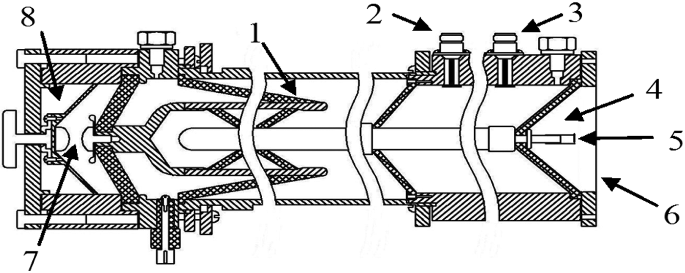
On setup 2, a VPG-30-200 generator with a longer rise time of the voltage pulse was used (Alekseev et al., Reference Alekseev, Lomaev, Rybka, Tarasenko, Shao, Zhang and Yan2013). The voltage acorss the discharge gap and the current through the gap or SAEB were measured simultaneously. The design of the VPG-30-200 generator is schematically shown in Figure 2. The main unit of the generator was an open-core resonance transformer (1) combined with a double coaxial forming line of wave impedance 60 Ω. The pulse transformer and generator circuit were similar in design to those used in the RADAN-303 generator (Yalandin & Shpak, Reference Yalandin and Shpak2001). The switch (7) of the double forming line was formed by two spherical stainless steel electrodes. The switch case, the double coaxial forming line, and the transmission line were made of duralumin, and the insulator was made of kaprolon. The switch was filled with nitrogen at a pressure not more than 8 atm. A breakdown of the switch generates a negative voltage pulse in the incident wave with amplitudes of 15–100 kV, a rise time of about 2 ns, and a FWHM of about 4 ns. The voltage pulse amplitude across the gas diode in the idle mode was varied from 30 kV to 200 kV. The wave impedance of the transmission line was 65 Ω.
Fig. 2. Schematic of the VPG-30-200 generator. 1 = resonance transformer; 2 = capacitive divider located in the beginning of the generator transmission line at 20 cm from the gas diode anode; 3 = capacitive divider located at 9 cm from the gas diode anode; 4 = gas diode; 5 = inter-electrode gap in the gas diode d; 6 = anode foil; 7 = inter-electrode gap in the generator switch; 8 = switch of the double forming line.
The cathode of the discharge gap (5) was a stainless steel tube whose inner diameter was 6 mm and edge thickness was about 100 µm. The plane anode through which the electron beam was extracted was made of 10-μm-thick Al foil. The electrode separation ranged from 4 to 20 mm. In the transmission line, there were two capacitive dividers. One divider (2) was used to measure the rise time and the amplitude of the incident wave, and the other divider (3) was used to measure the voltage across the discharge gap of the gas diode (4).
The discharge current was measured by a current shunt composed of chip resistors (size 1206). The net resistance of the shunt was 0.03 Ω. The number of runaway electrons in the beam downstream of the foil anode was measured by a collector with a receiving part diameter of 40 mm. The time resolution of this collector was about 0.6 ns. Signals from the collector, shunt, and dividers were recorded by a LeCroy WR204Xi oscilloscope (2 GHz, 10 GS/s).
3. EXPERIMENTAL RESULTS ON THE FIRST SETUP AND THEIR DISCUSSIONS
On setup 1, we preliminarily studied the discharge images and the radiation spectra in the discharges in SF6, SF6 mixture with 2.5% of nitrogen, air, and nitrogen. Figures 3a, 3c, 3d, 3e, 3f presents typical discharge images in SF6 for an inter-electrode gap of 13 mm at different pressures. For comparison, the discharge image in air at a pressure of 0.1 MPa is shown in Figure 3b. In the case of negative polarity of voltage pulse, a diffuse discharge in SF6 was formed at pressures ranging from 0.05–0.2 MPa. Bright spots were only visible at the electrode with small curvature radius (tubular electrode). As the pressure increased to 0.25–0.3 MPa, a diffuse corona discharge was ignited. Compared with the diffuse discharge, not only bright spots appear at the tubular electrode, but also, brighter spark streamers (leaders) with small length were visible at the cathode with batches of 20 pulses. In most of pulses, discharges formed in nitrogen under these conditions were also diffuse. However, all other things being equal, discharges in air at a pressure not more than 0.1 MPa, behaved a spark leader or spark channel in all cases (Fig. 3b).
Fig. 3. (Color online) Discharge images with negative (a, b, c, d) and positive (e, f) polarity of RADAN-220 generator in of SF6 (a, c, d, e, f) and air (b) for one (a, b, e) and 20 (c, d, f) pulses. Pressures of gases 0.1 (a, b, e), 0.2 (c, f), and 0.25 MPa (d). Tube electrode is from right side. d = 13 mm. Cathode is on the right side of the photos.
In the case of positive polarity of voltage pulse, the discharge in SF6 was either a diffuse discharge or a diffuse corona discharge (Figs. 3e, 3f). However, bright spots appeared not only at the tubular electrode but also at the plane electrode (Fig. 3e). In most of pulses, the discharges at pressures of 0.05, 0.1, and 0.15 MPa were all diffuse though they were less homogeneous than those in the case of negative polarity. The diffuse corona discharge was formed when the pressure exceeded 0.2 MPa (Fig. 3f). The formation of the diffuse discharge under the condition that the polarity of the electrode with small curvature radius was positive proved the fallacy that diffuse discharges were formed due to mono-energetic electrons with anomalous energy generated at the front of a polarized streamer near the cathode (Babich & Loiko, Reference Babich and Loiko1991; Babich, Reference Babich2003). Our studies showed that bright spots at the plane cathode arose after the formation of a diffuse discharge in the gap under this condition.
When an inter-electrode gap was 13 mm, diffuse discharges were obtained in SF6 mixture with 2.5% of nitrogen, air, argon, krypton, and nitrogen. As the inter-electrode gap and the gas pressure decreased, the transition from diffuse discharge to spark discharge was observed. Actually, it was the diffuse corona discharge that first arose, then a diffuse discharge. Only thereafter did the spark leaders cross the interelectrode gap, resulting in the generation of a spark (see also Shao et al., Reference Shao, Tarasenko, Zhang, Lomaev, Sorokin, Yan, Kozyrev and Baksht2012b).
As shown by spectral analysis, the major contribution to the radiation from the gap in a diffuse discharge was from bands of the second positive nitrogen system. Its radiation was detected by the photodetector in SF6-nitrogen mixture, air, and nitrogen at all pressures. In SF6 at decreased pressures, radiation of the second positive nitrogen system was also detected. This radiation was due to the presence of small amount of nitrogen in SF6 (less than 0.5%). However, the radiation intensity of the second positive nitrogen system in SF6 was much lower than that in nitrogen, air, and SF6 mixture with 2.5% of nitrogen. In this paper, in order to investigate the radiation from different gap regions, we used a mixture of SF6 with 2.5% of nitrogen, because in this mixture, the breakdown voltage of the gap was almost constant and the radiation intensity of the second positive nitrogen system increased an order of magnitude, making it possible to record the time at which radiation arose in different gap regions at all pressures.
It was reported that bright spots at the electrode with small curvature radius appeared in less than 1 ns (Baksht et al., Reference Baksht, Burachenko, Kostyrya, Lomaev, Rybka, Shulepov and Tarasenko2009), but their radiation intensity within the first nanoseconds was small. Scanning the spectrum ranged from 200 to 800 nm in the spark discharge, broadband radiation was observed with superimposed radiation of different narrow bands that were not identified in the work. Note that similar radiation spectra in SF6 were obtained even earlier (Baksht et al., Reference Baksht, Burachenko, Erofeev, Lomaev, Rybka, Sorokin and Tarasenko2008).
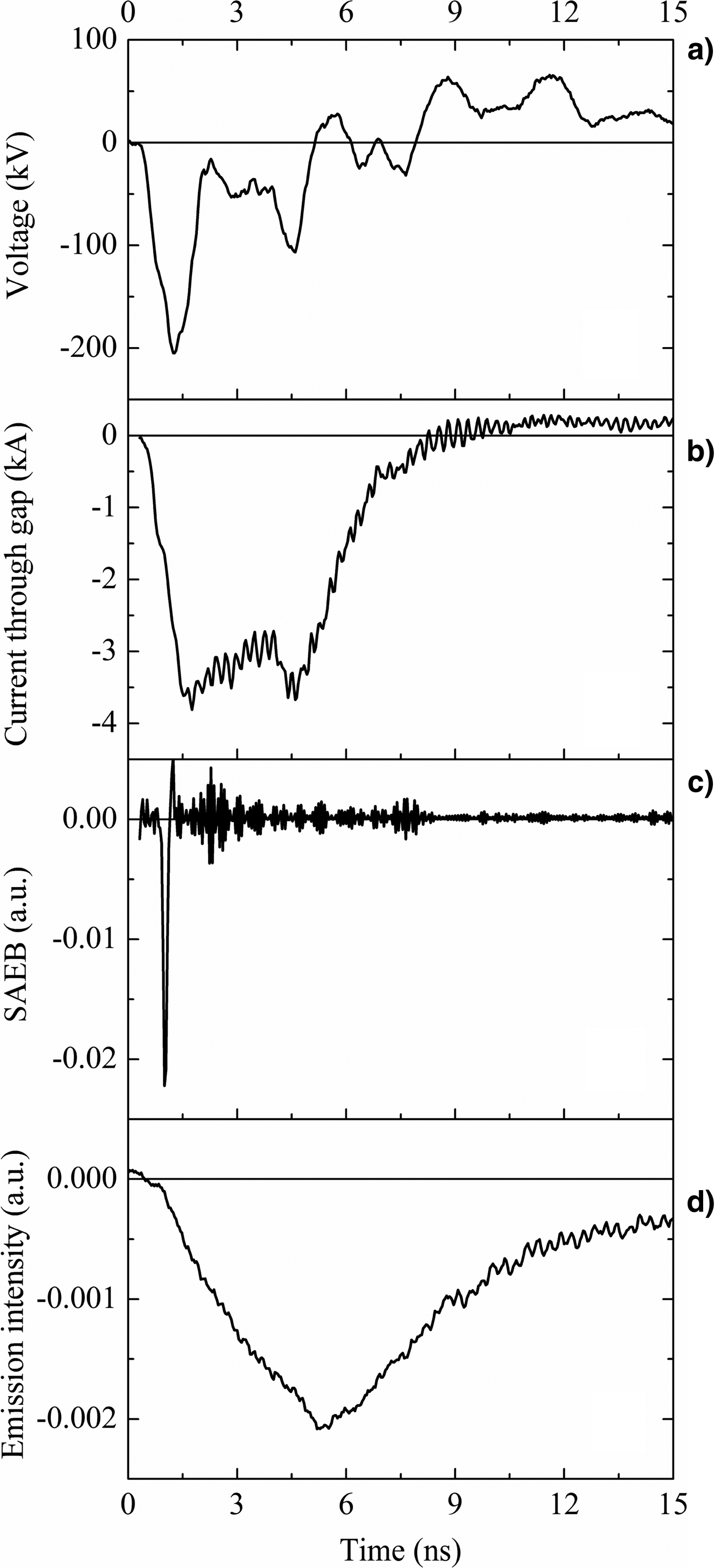
Waveforms of the voltage discharge current, and radiation from different gap regions were taken at both polarities of RADAN-220 generator at pressures ranged from 0.05 to 0.3 MPa. A SAEB was detected in most cases at negative polarity of the generator. Figure 4 shows waveforms of the voltage, discharge current, SAEB, and radiation in SF6 at a pressure of 0.05 MPa from the region near the electrode with small curvature radius. The waveforms were the average for approximately 30 pulses. All waveforms were synchronized in time with an accuracy of no longer than 0.2 ns, and their relative timing jitter with the DPO70604 oscilloscope was no longer than 40 ps. It was seen that the radiation from the discharge region arose during the rise time of the voltage pulse. For negative polarity, the SAEB was detected during the rise time of both the voltage pulse and discharge current. Similar sets of waveforms were obtained in SF6 at other different pressures as well as in other gases and gas mixtures. The inter-electrode gaps in these experiments were 13, 10, and 8 mm. However, in SF6, for both negative polarity with higher pressures and positive polarity for all gases, the SAEB could not be detected. All other things being equal, the highest SAEB amplitudes were obtained in nitrogen and air among next the gases: SF6, air, nitrogen, argon, and krypton.
Fig. 4. Waveforms of voltage pulses (a), current through gap (b), runaway electron beam behind foil (SAEB) (c), and emission intensity (d) near tube electrode with negative polarity of RADAN-220 generator, d = 13 mm. Pressure of SF6: 0.05 MPa.
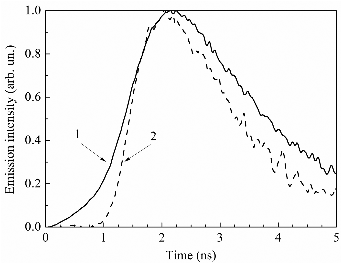
Through measuring the radiation from near-electrode regions of the gap, we observed that the radiation first arose at the electrode with small curvature radius and then at the plane electrode. Figure 5 shows waveforms of the radiation from the near-cathode (1) and near-anode regions (2) in SF6 mixture with 2.5% nitrogen at a pressure of 0.2 MPa when the polarity of the voltage pulse was negative. The data were obtained with the DSA 72504D oscilloscope with the relative timing jitter between light and voltage pulses of no longer than 10 ps. It was seen that the radiation pulse from the near-anode region appeared later than that from the near-cathode region. Such delay was due to the formation of an ionization wave whose front moved from the electrode with small curvature radius to the plane electrode. The passage of the ionization wave corresponded to the onset of efficient excitation and ionization in the gap. The ionization wave front velocity could be determined from the corresponding data, 2% of the peaks of emission intensities in the initial portions of waveforms of the radiation from different gap regions. The signal to noise ratio was ≥ 2. The measurements showed that in the SF6 mixture with 2.5% nitrogen, the delays of radiation from the near-anode region were longer than those in air and nitrogen. Furthermore, these delays increased with the gas pressure, and their values in SF6 and nitrogen at a pressure of 0.2 MPa were 0.7 and 0.26 ns, respectively. The radiation from the gap arose almost simultaneously at all pressures of the gases. Therefore, the delay of ionization processes corresponded to the onset of voltage rise in the gap did not completely depend on pressure, but depended on electric field amplification on micro- and macro-protrusions at the electrode with small curvature radius. Similar radiation dynamics were observed when positive voltage pulses applied to the potential electrode, but the delay in this case was shorter.
Fig. 5. Waveforms of emission intensity near cathode (1) and plane anode (2) in SF6 with 2.5% nitrogen at 0.2 MPa pressure. Negative polarity of RADAN-220 generator, d = 13 mm.
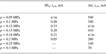
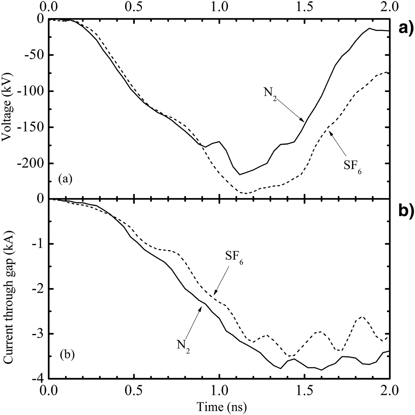
Figure 6 shows waveforms of the voltage in SF6 and air at different pressures with an inter-electrode gap of 8 mm. The corresponding waveforms of the SAEB in SF6 and air are presented in Figure 7. In the case of the RADAN-220 generator with a gap of 13 and 8 mm, the side walls of the gas diode were not covered with an insulator (Fig. 1). When the gap decreased from 13 to 8 mm, the SAEB amplitude in SF6 was increased and the RAE beam was obtained at a pressure of 0.2 MPa in SF6. The use of the insulator covering the side walls of the gas diode made it possible to obtain a SAEB with an inter-electrode gap of 10 mm at a pressure of 0.2 MPa in SF6. Comparison of the SAEB amplitudes in SF6, air, and nitrogen showed that under the same conditions, the SAEB amplitude in air and nitrogen was at least ten times higher than that in SF6 (see Table 1 and Fig. 7). This result was consistent with the data obtained earlier (Babich & Loiko, Reference Babich and Loiko1991; Baksht et al., Reference Baksht, Burachenko, Erofeev, Lomaev, Rybka, Sorokin and Tarasenko2008). In addition, all other things being equal, the FWHM of the SAEB pulse in SF6 were 15% higher than that in air.
Fig. 6. (Color online) Waveforms of voltage pulses in SF6 (a) and air (b) at different pressures. Negative polarity of RADAN-220 generator, d = 8 mm. (a) Pressures: 1–0.1, 2–0.15, 3–0.18, 4–0.2 MPa. (b) Pressures: 1–0.05, 2–0.1, 3–0.15, 4–0.2, 5–0.25, 6–0.3 MPa.
Fig. 7. (Color online) Waveforms of SAEB pulses in SF6 (a) and air (b) at different pressures. Negative polarity of RADAN-220 generator. (a) Pressures: 1–0.1, 2–0.12, 3–0.15, 4–0.18, 5–0.2 MPa. (b) Pressures: 1–0.05, 2–0.1, 3–0.15, 4–0.2, 5–0.25, 6–0.3 MPa. d = 8 mm.
Table 1. Average SAEB amplitude (for 30 pulses) in SF6 and air. Negative polarity of RADAN-220 generator, d = 8 mm
The SAEB amplitudes in air and nitrogen under the same conditions differed little. The SAEB amplitude in krypton at atmospheric pressure was 10 times lower than that in nitrogen and air but was little different from that in SF6. The SAEB amplitude in argon at atmospheric pressure was lower than that in nitrogen and air but much higher than that in krypton. From this comparison, it was obvious that the SAEB amplitude was more influenced by the atomic weight of a gas, more precisely, the electron energy lost in ionization and excitation, rather than by its electronegative properties.
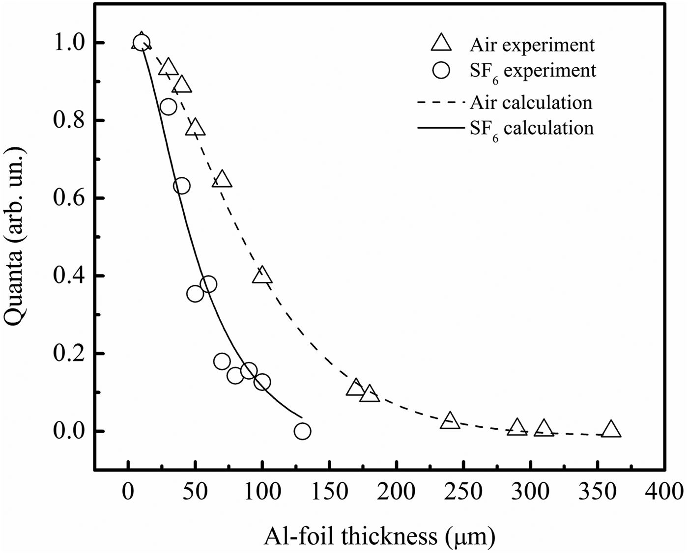
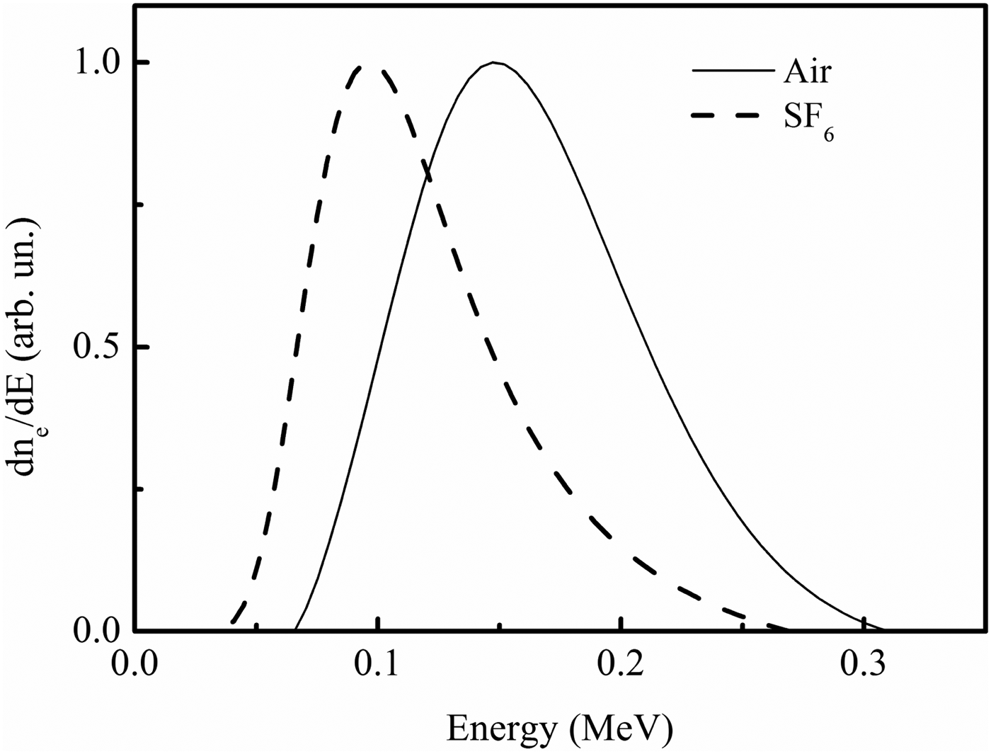
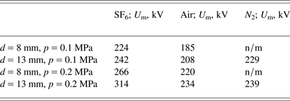
Figure 8 shows experimental the dependence of SAEB attenuation on the thickness of the foils. These attenuation curves were calculated by the procedure described in the paper (Baksht et al., Reference Baksht, Burachenko, Kozhevnikov, Kozyrev, Kostyrya and Tarasenko2010) and used to reconstruct RAE beam spectra. The RAE beam spectra reconstructed by this procedure for SF6 and air are shown in Figure 9. It was seen that the electron energy corresponding to the peak of the electron energy distribution in air was higher than that in SF6, though the maximum voltages across the gap in SF6 under similar conditions were somewhat higher than that in air and nitrogen (Table 2). The breakdown voltages in air and nitrogen under these conditions differ little, and increased with the pressure for all three gases. It should be pointed out that, in the spectra shown in Figure 9, only the main group of RAEs could be seen. The second group of electrons with energies less than 50 keV, which were detected in atmospheric air (Baksht et al., Reference Baksht, Burachenko, Kozhevnikov, Kozyrev, Kostyrya and Tarasenko2010; Tarasenko et al., Reference Tarasenko, Shpak, Shunailov and Kostyrya2005), was absent in these spectra, because these electrons were cut-off by the foil anode.
Fig. 8. Attenuation curves for the electron beams generated in SF6 and air at pressure 0.1 MPa. Negative polarity of RADAN-220 generator, d = 10 mm.
Fig. 9. Reconstructed spectrum of SAEB in SF6 and air at pressure 0.1 MPa. Negative polarity of RADAN-220 generator, d = 10 mm.
Table 2. The maximum voltages on the gap at different pressures of SF6, air and nitrogen and different gap spacing. Negative polarity of RADAN-220 generator
Waveforms of the current and voltage for SF6 and nitrogen at a pressure of 0.1 MPa are shown in Figure 10. All other things being equal, the discharge current for nitrogen was higher than that for SF6 while the maximum voltage for nitrogen was lower than that for SF6. However, these experimental data on conductivity in SF6 and nitrogen were inconsistent with the calculation results that the resistance in SF6 in the first nanosecond was two times lower than that in nitrogen and the amplitude of dynamic capacitive current for SF6 was also lower than that for nitrogen (Levko et al., Reference Levko, Gurovich and Krasik2012a). Actually, the dynamic capacitive current arose between the dense plasma front and the anode (Shao et al., Reference Shao, Tarasenko, Zhang, Burachenko, Rybka, Kostyrya, Lomaev, Baksht and Yan2013). In our opinion, it was mainly due to the lower velocity of the ionization wave front from the cathode to the plane anode in heavy electronegative gas (SF6). Furthermore, once the ionization wave front crossed the gap, the conduction current in SF6 was lower than that in nitrogen. Our measurements of the current through the gap confirmed the previous experimental data (Baksht et al., Reference Baksht, Burachenko, Erofeev, Lomaev, Rybka, Sorokin and Tarasenko2008; Reference Baksht, Burachenko, Kostyrya, Lomaev, Rybka, Shulepov and Tarasenko2009; Tarasenko, Reference Tarasenko2001). The plasma resistance in SF6 and in SF6-nitrogen mixture was higher than that in nitrogen under the same conditions.
Fig. 10. Waveforms of voltage pulses (a) and current through gap (b) in SF6 and nitrogen at pressure 0.1 MPa. Negative polarity of RADAN-220 generator, d = 13 mm.
4. EXPERIMENTAL RESULTS ON THE SECOND SETUP AND THEIR DISCUSSION
Figure 11 shows oscillograms of the voltage across the gap, discharge current, and SAEB at the rise time of the voltage pulse of about 2 ns. On the setup 2, the time resolution of the measuring system was about 0.5 ns, which was sufficient to record voltage pulses without any strong distortion and to measure the FWHM of the SAEB at low pressures in SF6 when the discharge transited to the “vacuum diode” mode (Tarasenko et al., Reference Tarasenko, Baksht, Burachenko, Kostyrya, Lomaev and Sorokin2010). Waveforms of the voltage across the gap for SF6 at different pressures are shown in Figure 12a, and waveforms of the beam current are presented in Figure 12b. Increasing the rise time of voltage pulse to about 2 ns could lead to a substantial decrease of SAEB current amplitude for SF6 at pressures higher than 200 Pa (Fig. 13). The SAEB amplitude decreased for both inter-electrode gaps (12 and 8 mm), and it was higher for the gap of 8 mm than that for the gap of 12 mm. At the pressure of 0.1 MPa, the SAEB amplitude for SF6 was more than an order of magnitude lower than that of air, further supporting the results obtained on setup 1. In addition, the increase of the FWHM of the beam current pulse at low pressures was related to the transition of the discharge to the vacuum diode mode.
Fig. 11. (Color online) Waveforms of voltage pulse, discharge current and SAEB behind foil at pressures of SF6 200 Pa. VPG-30-200 generator, d = 12 mm.
Fig. 12. (Color online) Waveforms of voltage pulses (a) and runaway electron beam current behind foil (b) at different pressures of SF6. VPG-30-200 generator, d = 12 mm.
Fig. 13. (Color online) SAEB amplitude vs. pressures of SF6 and air at different gap spacing. VPG-30-200 generator, d = 12 mm.
5. SAEB PARAMETERS FOR SF6
The conducted studies showed that the SAEB in SF6 had the following characteristics. First, the SAEB amplitude for SF6 was much lower (more than an order of magnitude) than that for air and nitrogen. The decrease of SAEB amplitude was mainly due to the much higher electron energy lost in the excitation and ionization in SF6 comparing with the electron loss in air and nitrogen. Furthermore, the effect of electron attachment on SF6 molecules was not strong. This followed from the fact that the SAEB amplitudes for air and nitrogen were almost the same (as known, air contains 21% of electronegative gas — oxygen) and that the SAEB amplitude for non-electronegative heavy gases (argon and krypton), was lower that for air and nitrogen.
Second, the diffuse discharge in SF6 was formed at both negative and positive polarities of the electrode with small curvature radius. In the case of positive polarity, SAEB from the gap was not detected, because the energies of RAEs here were too low. From our point of view, because of high efficiency of the characteristic radiation, the RAEs could participate in the formation of a diffuse discharge (Kozyrev et al., Reference Kozyrev, Tarasenko, Baksht and Shut'ko2011).
Third, under the conditions of both positive and negative polarities, the breakdown of the gap was due to the ionization wave whose front crossed the gap. The ionization wave velocity in SF6 was lower than that in nitrogen and air. It explained the phenomenon that the SAEB width for SF6 was longer than that for air and nitrogen. Moreover, with a large discharge gap, the ionization wave velocity decreased with the increase of the pressures of SF6, leading to the increase of the SAEB width (Baksht et al., Reference Baksht, Burachenko, Erofeev, Lomaev, Rybka, Sorokin and Tarasenko2008).
Fourth, the energy of the main group of RAEs in SF6 was lower than that in air. Furthermore, the said energy in both gases (SF6 and air) was lower than eU m.
6. CONCLUSION
From our studies, the following conclusions could be drawn:
• The SAEB amplitude for SF6 at pressures of 0.05–0.1 MPa is much lower than that for air and nitrogen and is commensurable with the SAEB amplitude for krypton. This is due to the increase of electron energy which is lost in excitation and ionization in heavy gases. The attachment of electrons plays a small role in SAEB generation, resulting in almost the same SAEB amplitudes in air and nitrogen.
• At a pressure of 0.1 MPa and the same voltage across the gap, the energy of RAEs generated in SF6 is lower than that in air.
• The diffuse discharge in SF6 and SF6-nitrogen mixture is formed not only at negative polarity but also at positive polarity of the electrode with small curvature radius.
• The obtained data confirm the generation mechanism of most of the RAEs between the ionization wave front and the plane anode. The SAEB width is substantially influenced by the ionization wave front velocity. The ionization wave velocity decreases with the increase of the pressure in SF6, nitrogen, and air. Comparing with the ionization wave velocity in air and nitrogen, the velocity is lower in SF6, so the SAEB width for SF6 is longer than that for air and nitrogen.
ACKNOWLEDGEMENTS
The work on the first setup was supported by RFBR under Grant #12-08-00105-a. The work on the second setup was supported by the National Natural Science Foundation of China under Grants 51222701, 51207154, the National Basic Research Program of China under Grant 2014CB239505, the Chinese Academy of Sciences Visiting Professorship for Senior international scientists under Grant 2012T1G0021, and the State Key Laboratory of Alternate Electrical Power System with Renewable Energy Sources under Grant LAPS14009.