1. INTRODUCTION
Maritime surveillance (Tunaley, Reference Tunaley2004; Guerriero et al., Reference Guerriero, Willett, Coraluppi and Carthel2008; Garcia et al., Reference Garcia, Guerrero, Luis and Molina2010) is indispensable to guarantee maritime domain awareness, which, in turn, is a prerequisite for a number of military and non-military applications such as ship traffic surveillance, identification of security threats and economic risks, monitoring both cooperative vessels and non-cooperative vessels. In particular, the development of ship group detection and tracking capabilities based on interpretation of satellite-derived information is vital for large-scale maritime surveillance. For military or security agencies, it is of particular interest to pay attention to non-cooperative passive systems for monitoring large-scale maritime activities. Non-cooperative systems are those that can observe a ship group's activities without their participation. Typical non-cooperative systems include radar imaging systems, optical imaging systems, acoustic surveillance and electronic intelligence (ELINT).
Multiple non-cooperative systems are often deployed together to achieve better surveillance performance. Many benefits can be achieved when using multi-sensor data fusion in multi-target surveillance systems (Zou et al., Reference Zou, Sun, Ji, Du and Lu2013). The data from each sensor can be used to complement the data of the other sensors to obtain broader coverage and more accurate target estimates and Identity (ID) decision and in turn eliminate the false tracks and countermeasures. Association of sensor measurements from multiple non-cooperative systems is a challenging problem as the surveillance area is generally large and the signal propagation environment is complex, making it difficult to associate observations from different sensors, due to timing, accuracy, and different types of sensor measurements. In addition, ship group surveillance poses particular challenges for spaceborne sensors: small targets need to be detected, wide areas need to be surveyed, and both targets and background are anything but stationary.
In this work, we aim to address the multi-sensor data fusion problem for large scale ship group surveillance, given a set of measurements obtained by optical imaging satellite and Electronic Intelligence (ELINT) satellite. Fusion of data from optical imaging and ELINT satellites is a challenging task. For an optical imaging system, high spatial resolution observing modes can provide ship characterisation and classification. Optical imaging can achieve sufficiently high resolution to allow vessel identification. However, the signals are sensitive to weather conditions and darkness, and the area coverage is relatively small. ELINT can be used to detect ships by their radar and other electromagnetic radiation. Although ELINT satellites can have a higher revisit frequency and often acquire dense and continuous measurements, ships may go undetected at some sampling intervals. In addition, there are spurious reports of possible targets, or clutter measurements that arise independently of the targets of interest.
Three basic alternatives, including raw data fusion, feature-level fusion and decision-level fusion, can be used for multi-sensor data fusion (Liggins et al., Reference Liggins, Hall and Llinas2008). As sensor data from optical imaging and ELINT satellites are not commensurate, they must be fused at the feature/state vector level or decision-level. Techniques for feature-level fusion typically extract features from multiple sensor observations and combine them into a single concatenated feature vector that is an input to pattern recognition techniques such as neural networks, clustering algorithms, or template methods. Decision-level fusion combines sensor information after each sensor has made a preliminary determination of an entity's location, attributes, and identity. Examples of decision-level fusion methods include weighted decision methods, classical inference, Bayesian inference, and Dempster-Shafer's (D-S) (Dempster, Reference Dempster1968; Shafer, Reference Shafer1967) method.
We propose a novel decision-level fusion framework for large-scale ship group surveillance using spaceborne optical imaging satellite data and ELINT satellite data. Each target in the measurements is treated as an independent mass point, and multi-target association is accomplished by coherent point set analysis using both topological and attributive features within the framework of D-S theory. The flowchart of our method is shown in Figure 1.

Figure 1. Flowchart of our proposed framework.
The contributions of our work are threefold. Firstly, a novel Coherent Point Set (CPS) analysis framework is proposed for the fusion of optical imaging satellite data and electronic intelligence satellite data for large-scale maritime surveillance. To the best of our knowledge, this work is the first to investigate CPS for multimodal remote sensing data fusion. Secondly, multi-scale features including both category-level attributes and topology attributes are exploited in CPS and this ensures that ship groups can be correctly associated under noisy measurements or with imperfect detection. Thirdly, extensive experiments on simulated and recorded data have been carried out to verify the effectiveness and robustness of the proposed method under various scenarios.
The rest of this work is organised as follows. In Section 2, ship detection in optical imaging data and ELINT records is presented. Section 3 gives a detailed description of the category-level attributes and topology attributes for ship groups. Section 4 reports the CPS analysis framework. Experimental results are presented in Section 5 and finally Section 6 concludes the paper.
2. SHIP DETECTION AND ATTRIBUTE EXTRACTION
2.1. Ship Detection in Optical Imaging Data
For optical ship detection, we have trained a hybrid generative-discriminative model. To remove the effect of false alarms caused by land areas, land/sea area segmentation is firstly performed based on Geographical Information System (GIS) information. Both shape features and texture features are then exploited for optical ship modelling. In our experiments, a Histogram of Gradient (HOG) feature (Dalal and Triggs, Reference Dalal and Triggs2005) is computed for shape modelling and a pyramid binary pattern feature (Sun et al., Reference Sun, Wang, Wang and El-sheimy2011) is computed for texture modelling.
The hybrid learning model involves two processes: offline training process and online detection process, as shown in Figure 2. For offline training, the Expectation Maximization (EM) algorithm is used to fit the Probabilistic Latent Semantic Analysis (PLSA) (Hofmann, Reference Hofmann2001) model. (The feature set is denoted by F= {f 1, f 2, …, f M}, the target set is denoted by O= {o 1, o 2, …, o N}, and the latent topic set is denoted by Z= {z 1, z 2, …, z K}). After learning the model parameter P (f i|zk) and P(z k|oitrain), each training sample can be represented by a K-dimensional vector P(z|o itrain). Then a discriminative four-category (including cloud, island, ocean wave and ship) Support Vector Machine (SVM) classification model is learned using P(|o itrain) and its corresponding category label. During online detection, the model parameter P(f i|zk) from training samples is used to fit the PLSA model of testing samples. The learned SVM model is then adopted to categorise the testing samples based on P(z|otest).
Figure 2. Ship detection in optical images.
2.2. Trajectory Clustering of ELINT Records
ELINT satellites are designed to intercept radar emissions. ELINT involves the collection and analysis of intercepted signals by other than the intended recipient. It involves the exploitation of signal “externals,” referring to the characteristics of the actual transmitted signal (including frequency of carriers and subcarriers, modulation, bandwidth, power level, etc.), beam footprint parameters, and emitter location and motion. A collection signal parameter can be used to obtain a Radio Frequency (RF) fingerprint for each emitter/emitter platform, which can then be used to locate and rapidly identify the specific emitter or emitter type in subsequent intercepts.
As ELINT acquires dense observation of target position and attribute in a short period, target detection in ELINT data is essentially a trajectory-clustering problem. We proposed a two-level clustering algorithm for target detection in ELINT data (as shown in Figure 3). Radiation signals are firstly classified by their RF fingerprints. Then, spatial-temporal constraints are applied to cluster signals with similar RF fingerprints into meaningful trajectories.
Figure 3. Trajectory clustering of ELINT measurements.
3. SHIP GROUP ATTRIBUTE EXTRACTION
Considering that the size of a ship is often less than the distance between different ships for large-scale maritime surveillance, we treat each ship as a mass point and ship groups are modelled as point sets.
3.1. Category-level Attributes
As measurements from ELINT records and optical imagery are different, a unified definition of target attributes would benefit the fusion process. Considering that target category is of particular interest for tactical and strategic operational analysis in large-scale maritime surveillance, ship attributes are defined as the probability of belonging to a specific class.
For ELINT satellites, the carrier frequency, pulse width and repetition interval of the radiation source signal can be obtained after splitting up the intercepted signal and feature extraction. With the support of an intelligence database (which is acquired offline by manual efforts), we can identify the target category based on the radiation source. However, it should be noted that targets from the same category can carry different types of radiation source and the same type of radiation source can be carried by different target categories. Let R= {R t|t ∈ [1, T]} and C= {C m| m ∈ [1, M]} denote the radiation source set and target category set respectively, U i denotes the Electronic Reconnaissance (ER) record of target i and the ER measurement can be written as:
 $$U = \left\{ {U_1, U_2, \cdots U_n} \right\},U_i = \left\{ {U_{i1}, U_{i2} \cdots, U_{iT}} \right\}$$
where U it denotes the probability of target i carrying radiation type R t. This is computed by extracting the carrier frequency, pulse width and repetition interval of the radiation signal and matching these features to the database. Based on the relationship between radiation source and target categories from intelligence database, we can get:
 $$V_t = \left\{ {V_{t1}, V_{t2}, \cdots V_{tM}} \right\}$$
where V tk denotes the probability of radiation source R t carried by target category C k. The probability that target i belongs to target category C k based on ELINT measurement is then computed as:
 $$s_{ik} = \sum\limits_{t = 1}^N {U_{it} V_{tk}} $$
For optical observations, we can perform object category recognition using various features. The aspect ratio (length/width) of different ships is a simple yet very robust discriminative feature and is used for optical attributes computation. Considering that the extraction of aspect ratio of different ships in optical imagery may suffer from measurement error, fuzzy set theory is introduced for ship category description and a modified normal distribution is used as the membership function:
 $$p_{i'k} = \left\{\!\!\matrix{\exp \left[ { - \displaystyle{{\left( {t_{i'} - L_{k1}} \right)^2} \over {2\sigma ^2}}} \right],\quad t_{i'} \le L_{k1} \cr 1,\quad L_{k1} \lt t_{i'} \lt L_{k2} \cr \exp \left[ { - \displaystyle{{\left( {t_{i'} - L_{k2}} \right)^2} \over {2\sigma ^2}}} \right],\quad t_{i'} \ge L_{k2} } \right.$$
where p i′k denotes the probability that target i′ belongs to target category C k, σ is the limit coefficient and is determined based on empirical estimate, t i′ denotes aspect ratio of target i′, [C k1, C k2] is the dynamic range of C k.
Combining category-level attributes from ELINT observations and optical imaging satellite observations, the basic probability assignment function is given as:
 $$Sp_{ii'} = \sum\limits_{k = 1}^M {s_{ik} p_{i'k}} $$
The basic probability assignment function of point pairs s i↔t i′ and s j↔t j′ based on category-level attributive characteristics can be computed as follows:
 $$Sp\left( {i,j,i',j'} \right) = Sp_{ii'} Sp_{\,jj'} $$
3.2. Topology Attributes
Motivated by the observation that ship groups performing tactical or strategic operations often have a stable topology in a short time period, we present a robust point set geometric descriptor, named Point Pair Topological Characteristics (PPTC). The computation process of the PPTC descriptor is shown in Figure 4.
Figure 4. Point set topology descriptor.
Given a point set S composed of n points, the PPTC of point s j relative to point s i is:
 $$PP_{ij} (s_i ) = \left\{ {\rho \left( {s_i, s_j} \right){\rm,} \theta \left( {s_i, s_j} \right)\vert s_i, s_j \in S} \right.\left. {;\rho \left( {s_i, s_j} \right) \in \left[ {1,p} \right];\theta \left( {s_i, s_j} \right) \in \left[ {1,q} \right]} \right\}\;$$
where m s is the mass centre of the point set, ρ (s i, sj) denotes the normalized distance from point s j to point s i, θ(s i, sj) denotes the normalized angle between vector  $\mathop {{\bi s}_{\bi i} {\bi s}_{\bi j}} \limits^ \to $ and vector $\mathop {{\bi s}_{\bi i} m_{\bi s}} \limits^ \to $, p and q are the quantized number of distance and angle respectively. The PPTC descriptor of a point set is formed by concatenating all PP ij(s i) together. The PPTC descriptor has several advantages for topology preservation. Firstly, it normalizes and quantizes the logarithm distance between point pairs. It is insensitive to measurement error such as point position deviation. Secondly, each point set has its separate coordinate system, which makes the descriptor robust to inaccurate orientation between point pairs. Thirdly, the PPTC is a global topology descriptor and it is robust to noise and local measurement errors.
Based on the PPTC descriptor, a new basic probability assignment function of point pairs s i↔t i′ and s j↔t j′ is computed as follows.
 $$\alpha = \exp \left( {{{ - \displaystyle{{\left\vert {\rho _{i'} \left( {t_{i'}, t_{\,j'}} \right) - \rho _i \left( {s_i, s_j} \right)} \right\vert } \over {\mathop {\max} \limits_{m,n'} \left\{ {\rho _m \left( {s_m, s_n} \right),\rho _{n'} \left( {t_{n'}, t_{m'}} \right)} \right\}}}} \Bigg/ {\sigma _\alpha ^2}}} \right)$$
 $$\beta = \exp \left( {{{ - \displaystyle{{\left\vert {\theta _{i'} \left( {t_{i'}, t_{j'}} \right) - \theta _i \left( {s_i, s_j} \right)} \right\vert } \over {\mathop {\max} \limits_{m,n'} \left\{ {\theta _m \left( {s_m, s_n} \right),\theta _{n'} \left( {t_{n'}, t_{m'}} \right)} \right\}}}} \Bigg/ {\sigma _\beta ^2}}} \right)$$
 $$Cp_{ij,i'j'} = \left( {1 - \alpha} \right)\left( {1 - \beta} \right)$$
 $$Cp(i,j;i\hskip1pt',j\hskip1pt') = 1/(1 + \left( {Cp_{ij,i\hskip1pt'j\hskip1pt'} + Cp_{ji;j'i'}} \right)^2 )$$
where α and β denotes the similarity of logarithm distance and angle between point pairs, σ α and σ β denotes covariance of distance and angle respectively, Cp ij,i′j′ is the similarity between Pt ij(s i) and Pt i′j′(t i′), Cp(i, j;i′, j′) is the basic probability assignment function of s i↔t i′ and s j↔t j′. Small values of Cp ij,i′j′ indicates a high level of topology similarity.
4. SHIP GROUP ASSOCIATION
4.1. Coherent Point Set (CPS)
Given the template point set S= {s 1, s 2, …, s n} from optical satellite data and the target point set T= {t 1, t 2, …,t m} from ER satellite data, our goal is to fuse the observations by point set association matrix M = [M ij]n×m, whose element M ij ∈ [0, 1] denotes the corresponding relationship between s i ∈ S and t j ∈ T. If the similarity measurement of (s i, tj) is C ij, the cost matrix of matching the two point sets is:
 $$C(S,T,{\bi M}) = \sum\limits_{i = 1}^n {\sum\limits_{\,j = 1}^m {M_{ij} C_{ij}}} $$
Association of multi-target groups is equivalent to finding the optimized point set association probability matrix  ${\bi \hat M}$ under the constraint of one-to-one mapping.
 $${\bi \hat M} = \arg \mathop {\min} \limits_{\bi M} C(S,T,{\bi M})$$
In order to combine ship group category-level attributes and topology attributes efficiently within a unified framework, we use the D-S evidence theory. The core idea of D-S evidence is to get the total basic probability assignment function by integrating the basic probability assignment function of each item of evidence. The synthesized basic probability assignment function can be computed as:
 $$C(i,j,i',j') = \displaystyle{{\sum\limits_{\alpha = (i \leftrightarrow i',j \leftrightarrow j')} {Cp(m_1, n_1 ;m_1 ^\prime, n_1 ^\prime )*Sp(m_2, n_2 ;m_2 ^\prime, n_2 ^\prime )}} \over {1 - \sum\limits_{\alpha = \Phi} {Cp(m_1, n_1 ;m_1 ^\prime, n_1 ^\prime )*Sp(m_2, n_2 ;m_2 ^\prime, n_2 ^\prime )}}} $$
where α= (m 1↔m 1′, n 1↔n 1′) ∩ (m 2↔m 2′, n 2↔n 2′). To get a global coherent result, relaxation labelling technique (Ouyang et al., Reference Ouyang, Ji and Tian2012) is used to refine the iterative process. Firstly, we obtain the initial association probability matrix M (0) = [M ij(0)](n+1)×(m+1) by C(i, j;i′, j′), where M ij(0) is the initial probability of s i↔t j. For any point s i′ (i′ ≠ i), only one point t j′ (j′≠j) is associated with t j. Let  $\mathop {\max} \limits_{\,j' \ne j} \left[ {C(i,j;i',j')} \right]$ denote the support of s i′↔t j′ for s i↔t j, the initial association probability matrix M ij(0) is the average support for s i↔t j from all s i′↔t j′ (i′≠i, j′≠j). At the rth iteration (r > 0), the support [M ij(r)](n+1)×(m+1) of s i′↔tj′ for s i↔t j is not only related to C(i, j;i′, j′) but also to M i′j′(r−1).
4.2. Sensitivity Analysis
We simulate a scenario of maritime surveillance of 100 × 100 kilometres, where a ship group of nine ships from four different categories [L 1, L 2, L 3, L 4] is present, including one ship from category L 1, two ships from category L 2, three ships from category L 3 and three ships from category L 4. The ground truth of ship numbers for optical imaging satellite and ELINT satellite is denoted by nP = nQ= 9. For optical imaging measurement, an image with 5000 × 5000 pixels of 20 metres resolution is generated. Nine points are randomly selected from the image as the template points. Each point has a corresponding aspect ratio k ratio drawn from [L k1, L k2] of category L k as its optical attribute. The observed aspect ratio is randomly generated from [L k − σLk, Lk + σL k] where σ is the deviation error. The ELINT observations are simulated by transforming the optical point positions with a similarity transformation. The transformation parameters are 0·1 ⩽ s⩽5·0, −π ⩽ θ ⩽ π, −2000 ⩽ t x, ty ⩽ 2000, where s is the scale factor, θ is the rotation angle, t x and t y are the displacements. As the ELINT data and optical image data have different location precision, a zero mean Gaussian noise with covariance δ = f × d minT (d minT is the minimum distance between targets, f is the noise level factor) is added to the ER position. There are also false alarms in the ELINT observations and they are modelled by adding nQ o = γ × nQ points to the ELINT data.
For the simulated experiments, we use the parameters setting f= 1, σ= 0·5, s= 0·9, θ = −(3/4) π, the results using different methods with nQ o = 0 and nQ o = 20 are shown in Figure 5 respectively. The red icons denote observation points from ELINT data and the green icons denote observation points from optical data. The geometrical forms denote target type. In both ELINT and optical data sets, point category information is given manually.
Figure 5. Association results using simulated data. (a) nQ o = 0. (b) nQ o = 20. The left column shows association results using topology features, the middle column shows association results using category-level attributes, and the right column shows association results of the proposed method.
To test the robustness of the proposed algorithm to the location noise, the target size deviation and the outliers, we ran two groups of experiments on the simulated data with different degrees of noise and different levels of outlier ratio. We ran 200 experiments for each group. Figure 6 shows the correct matching rate varying with the noise level factor f and the target size deviation error σ. The results demonstrate the robustness of our proposed method.
Figure 6. Robustness to measurement error. (a) The correct matching rate varying with f. (b) The correct matching rate varying with σ.
5. EXPERIMENTAL RESULTS
To verify the effectiveness of the proposed CPS method for large-scale ship group surveillance, three groups of experiments on real world recorded data have been carried out. Ship detection statistics in optical images and ELINT records are presented in Section 5.1 and Section 5.2 respectively, and ship group association results are given in Section 5.3.
5.1. Optical Ship Detection Results
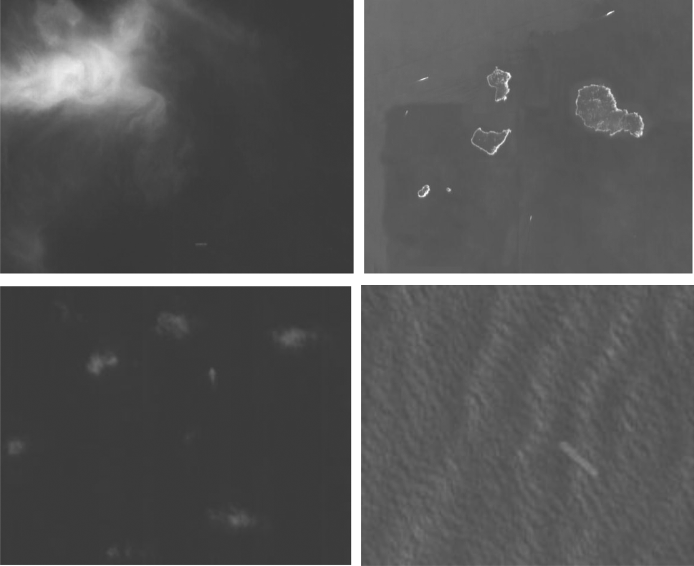
We collected 316 optical images from CBERS and SPOT 4 satellites. The resolution ranges from ten to five metres, some typical samples of test images are shown in Figure 7. 1653 candidate ship region images were obtained after land/sea segmentation and candidate ship area detection. In our experiments, the candidate ship region images have been partitioned into two randomly selected halves: one half forms the training set and the other forms the testing set. The training set consists of 495 randomly selected images. The rest of the images in the data forms the testing set for separate performance evaluation. The optical ship model learnt from the training data is used to classify images in the testing set into either ships or background.
Figure 7. Several typical samples of testing images.
To measure the performance of optical ship detection, the following parameters are used:
 $$Recall = \vert N_C\vert\hskip-5pt\bigg/\hskip-5pt\vert N_G\vert, Precision = \vert N_C\vert\hskip-5pt\bigg/\hskip-5pt\vert N_D\vert}$}}$$
where N c, NG, ND represents the number of correctly detected, ground truth and actual detected ships, respectively.
We compare our method with two state-of-the-art methods including Principal Component Analysis and K-Nearest Neighbour (PCA+KNN) and Feature+SVM (Zhu et al., Reference Zhu, Zhou, Wang and Guo2010). The PCA+KNN method is selected as it is the baseline method for optical ship category classification and the Feature+SVM method is selected as it is the most successful paradigm in the literature. PCA+KNN method firstly performs principal component analysis on the extracted features and then classifies candidate ship images using KNN (In our experiments K= 7). Feature+SVM method directly inputs the extracted features to SVM classifier. We have carried out two groups of experiments. In the first group, candidate ship images are classified into ships and background (two-class strategy). In the second group, the background category is further classified into cloud, island, ocean wave and background (multi-class strategy). The results are reported in Table 1 and Table 2 respectively.
Table 1. Statistical result of different methods using two-class strategy.

Table 2. Statistical result of different methods using multi-class strategy.

5.2. ELINT Trajectory Clustering Results
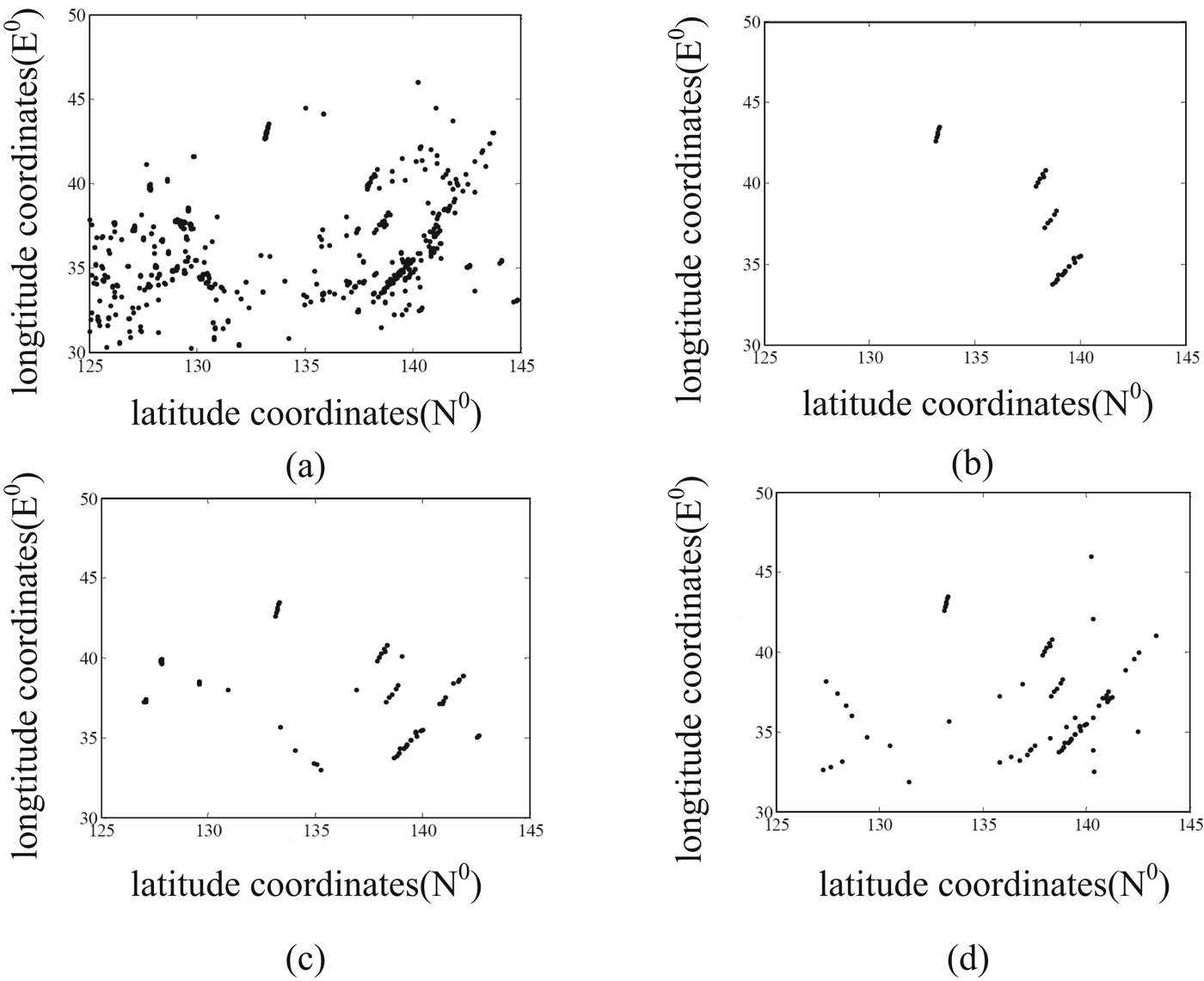
To verify the effectiveness of our trajectory clustering algorithm in ELINT records, our two-level clustering algorithm has been compared to clustering methods based on logical rules and Hough transform using two sets of recorded data. The results are shown in Figure 8 and Figure 9. It can be seen that our algorithm recovers the most meaningful trajectories.
Figure 8. (a) ELINT Records. (b) Trajectory clustering results of our algorithm. (c) Trajectory clustering results based on logical rules. (d) Trajectory clustering results based on Hough Transform.
Figure 9. (a) ELINT Records. (b) Trajectory clustering results of our algorithm. (c) Trajectory clustering results based on logical rules. (d) Trajectory clustering results based on Hough Transform.
5.3. Association Results using Recorded Data
To test the proposed algorithm in real-world applications, ships detected in the SPOT 4 optical remote sensing image (20 m resolution) forms the template point set, the location of the radiation source from the ELINT sensor observation forms the target point set. The template point set has seven members (as shown in the left column of Figure 10 (a)) while the target point set has 17 members (as shown in the right column of Figure 10 (a)). The template points and target points are depicted by different point markers.
Figure 10. Association results using recorded data. (a) Association results. (b) The association matrix.
Both shape features and texture features are exploited for optical ship modelling in the template points. Radiation signals in the target point set are classified by their RF fingerprints. For category-level attribute characterization, ships have been classified into four categories, namely aircraft carrier, cruiser, frigate and depot ship. The topology attribute descriptor is computed from the relative position of different ships in the group.
The association results using both category-level attributes and topology attributes under the framework of CPS are shown in Figure 10. Figure 10 (a) gives the visualized demonstration while Figure 10 (b) shows the numerical values of the association matrix. As a time delay exists in the optical image and the ELINT record and the ship groups in the template set and target set are not the same, it can be seen from Figure 10(a) that the CPS are robust to topology distortions. ELINT records usually have more false detections and thus generate lots of outliers in the target set. The association matrix in Figure 10(b) demonstrates our method can obtain the correct association under the presence of multiple outliers. It is suitable for real-world application scenarios.
6. CONCLUSIONS
In this work, we propose a novel decision-level fusion framework for large-scale ship group surveillance using spaceborne optical imaging satellite data and ELINT satellite data. The proposed framework consists of three major steps: target detection, attributes extraction and evidence fusion. Considering that the size of a ship is often less than the distance among different ships for large-scale maritime surveillance, each target in the measurements is treated as an independent mass point, and multi-target association is accomplished by coherent point set analysis using both topological and attributive features. Experimental results on both simulated and recorded data have demonstrated the robustness and effectiveness of the proposed algorithm.
FINANCIAL SUPPORT
This work was supported in part by the National Natural Science Foundation of China under Grant 61303186, 61240058, and by the Ph.D. Programs Foundation of Ministry of Education of China under Grant 20124307120013.