


Introduction
With the aim of increasing performance, quality, and profitability while decreasing the amount of waste, development time, and cost, advanced manufacturing (AM) is making rapid gains in materials research, product design, and commercialization [Reference Thompson, Moroni, Vaneker, Fadel, Campbell, Gibson, Bernard, Schulz, Graf, Ahuja and Martina1, Reference Maiyar, Singh, Prabhu and Tiwari2, Reference Dizon, Espera, Chen and Advincula3, Reference Szentmiklosi, Maroti, Kis, Janik and Horvath4, Reference Attaran5]. Advanced materials research ranges from ways to reduce anisotropy [Reference Levenhagen and Dadmun6, Reference Mooney, Kourousis and Raghavendra7, Reference Levenhagen and Dadmun8] for three-dimensional (3D) printing and other techniques to imbuing common AM feedstocks with additional functionality, such as sensors [Reference Christ, Aliheidari, Ameli and Potschke9], antimicrobial agents [Reference Teo, Ong, Chong, Zhang, Lu, Moochhala, Ho and Teoh10], or drug delivery [Reference Alhijjaj, Belton and Qi11, Reference Kollamaram, Croker, Walker, Goyanes, Basit and Gaisford12]. The AM technique most associated with 3D printing, known as fused filament fabrication (FFF), heats a thermoplastic polymer past its glass transition temperature (T g) or melting point (T m) and deposits the material into layered cross sections via a printing nozzle. The deposited material subsequently cools down and undergoes interfacial adhesion between each layer, which forms a 3D part. FFF printed parts are modeled first in computer software, and as a consequence can possess complex geometries while allowing for agile requirement changes and fabrication. When deciding on which polymer materials to use for FFF, acrylonitrile butadiene styrene (ABS) is traditionally chosen if the final product needs mechanical strength and impact resistance, which has made it the second-most common 3D printing polymer, after poly(lactic acid). Applications requiring these mechanical properties and many other capabilities have a variety of materials to choose from for FFF and more generally AM; however, there are relatively few state-of-the-art printing feedstocks that deal directly with being used in extreme environments where ionizing radiation, harsh chemical species, such as solvents, or elevated temperatures and mechanical stresses are existent.
In a recent published study, commercial ABS filaments containing various concentrations of elemental bismuth (up to 18 wt%) were evaluated as phantom devices to mimic the radiopacity of native tissues during X-ray CT imaging and as safety labware [Reference Ceh, Youd, Mastrovich, Peterson, Khan, Sasser, Sander, Doney, Turner and Leevy13]. The authors demonstrated that the 2.0 mm ABS filament with the highest Bi concentration attenuated half of the 99mTc gamma emission. Needless to say that filaments containing higher weight percent of Bi loadings would provide even better shielding at comparable thickness, but unfortunately these are not commercially available. More recently, Woosley et al. demonstrated the feasibility of creating ABS filaments containing up to 20 wt% boron nitride (BN) for potential aerospace applications [Reference Woosley, Galehdari, Kelkar and Aravamudhan14]. Neutron attenuation of the 3D printed pads increased from 50% for the neat ABS polymer to 72% for the 20 wt% BN composite. Greater attenuation values were not feasible since BN loadings higher than 20 wt% produced poor quality filaments. Both studies illustrate well the potential of using FFF to create unique objects, but the application of the technology remains restricted due to the availability of functional filaments: either these are not available or are limited to relatively low loadings of additives that exhibit the desired functional characteristics. Furthermore, ionizing radiation is frequently present in environments that combine other harsh conditions as well, like those encountered in the storage of radioactive waste (solvents), nuclear power plants (high humidity, high temperatures), etc. Thus, it is important to consider approaches for filament fabrication that allow for easy material customization to address a range of functionalities.
In this work, we describe the preparation of highly filled FFF filaments containing three different components: ABS, Bi, and polyvinylidene fluoride (PVDF). PVDF is an attractive hydrophobic polymer to be incorporated in the fabrication of filaments since it exhibits high chemical resistance [Reference Kar, Biswas and Bose15, Reference Kar, Biswas and Bose16] and is widely used in numerous applications from electrical storage [Reference Abdalla, Obaid and Al-Marzouki17] to membrane filtration, distillation, and ion exchange [Reference Liu, Shen, Zhao and Chen18, Reference Liu, Hashim, Liu, Abed and Li19]. Our filaments were created to be used by the FFF technology to 3D print objects that would experience combined extreme environments, such as exposure to ionizing radiation and solvent species. As such, homogeneous ABS-composite filaments were made of increasing concentrations up to 66 wt% loading of bismuth for attenuating gamma radiation and up to 25 wt% loading of PVDF to increase chemical resistance. The filaments were printed into blocks via an FFF technique, characterized to understand their chemistry and thermal and mechanical properties, and subjected to gamma radiation from a Cs-137 source to evaluate their shielding ability and tolerance to radiolysis.
Results and Discussion
Chemical characterization
Fourier transform-infrared spectroscopy (FTIR) was performed to confirm that the feedstock material successfully incorporated all of the constituent polymers. The spectra of five typical samples are shown in Fig. 1(a). Relevant IR information for the polymer composites includes peaks corresponding to C–H alkane bonds between 3000 and 2850 cm−1; C–H alkene bonds between 3100 and 3010 cm−1; C=C aliphatic bonds between 1680 and 1620 cm−1; C=C aromatic bonds between 1700 and 1500 cm−1; C≡N nitrile bonds between 2260 and 2200 cm−1; C–F alkane bonds between 1400 and 1000 cm−1; and C–H aromatic bonds between 3100 and 3000 cm−1. All five spectra in Fig. 1(a) have the characteristic peak of a nitrile group around 2250 cm−1, which is associated with ABS [Reference Lin-Vien, Colthup, Fateley, Grasselli, Lin-Vien, Colthup, Fateley and Grasselli20]. The 3D printed pads containing PVDF show additional peaks from 1000 to 1400 cm−1, which correspond to carbon–fluorine bonds. The IR data confirm that both polymers were successfully incorporated in the diverse 3D printed pads, thus validating our approach for filament fabrication.

Figure 1: (a) FTIR spectra of printed samples and (b) MXRF of a Bi color mapping of ABS/Bi 34/66.
Micro X-ray fluorescence (MXRF) experiments were performed to detect and evaluate the distribution of bismuth in the filament. A typical color mapping of a 34 wt% ABS and a 66 wt% Bi filament is shown in Fig. 1(b). The filament is at an angle so that a top view and a side view can be seen. Bismuth particles are scattered throughout the filament bulk and surface, confirming that the feedstock material has successfully incorporated the filler.
Both techniques were also employed to determine whether 3D printed pads show the evidence of degradation after being subjected to gamma irradiation. The formation of peroxide radicals on the polymer backbone evidenced by the detection of OH groups at 3500 cm−1 in the IR spectrum would indicate changes in the chemical structure due to radiolysis and oxidation. The FTIR spectrum for the irradiated ABS/Bi/PVDF 25/50/25 sample is similar to the control sample as shown in Fig. 2(a) indicating good tolerance to ionizing radiation. The MXRF characterization of the same samples is shown in Figs. 2(b) and 2(c). MXRF images are a top view of the cross section of two different printed samples from the same batch of printing: one that was not irradiated and one that was irradiated. They both display information about the interior and exterior of the specimen. The color mapping shown in the figure is for Bi in printed ABS/Bi/PVDF 50/25/25 samples, which is fairly uniform throughout before and after irradiation. Thus, the fabrication procedure results in a homogeneous printed material which is retained after irradiation.

Figure 2: (a) FTIR and MXRF of (b) pre- and (c) post-irradiated samples showing an even distribution of bismuth and that it does not change after irradiation. Because the samples are oriented along the viewing axis, the green coloration corresponds to the top layer and the blue coloration corresponds to the deeper layers.
Morphological characterization
The complex morphology of the composite filaments was probed using the ultra-small-angle X-ray scattering (USAXS) and small-angle X-ray scattering (SAXS) techniques. X-rays are scattered by fluctuations in electron density in three dimensions, such that the scattering pattern of materials gives significant insight into the spatial arrangement of scattering objections. In the case of complex composite materials, scattering objects can be inorganic particles, amorphous polymer domains, crystallites, or crystallographic faces depending upon the angle of scattered X-rays. Using a combination of USAXS and SAXS techniques, we are able to probe fluctuations in electron density across real space dimensions of approximately 3 Å up to 3 μm. Pure ABS and pure PDVF used for the composites each display distinct scattering patterns, as shown in Fig. 3. Pure ABS and ABS/Bi composites were also investigated and are shown in Supplementary Fig. SI2. The inter-lamellar spacing (Long Period, L p) of pure PVDF appears prominently around q = 0.06 Å−1, corresponding to 10.4 nm. The determined L p of pure PVDF filaments is in agreement with previous synchrotron SAXS data obtained for PVDF [Reference Guo, Zhang, Xue, Cai, Shang, Li, Chen, Wu and Jiang21, Reference Wang and Cakmak22]. Pure ABS polymer displays distinct micro-phase separation in the USAXS region with scattering features around q = 0.0013, 0.005, and 0.014 Å−1. Interestingly, the micro-phase separated morphology of pure ABS is not present in the composite blends, likely due to scattering from Bi particles dominating the scattering profile at these scattering angles.
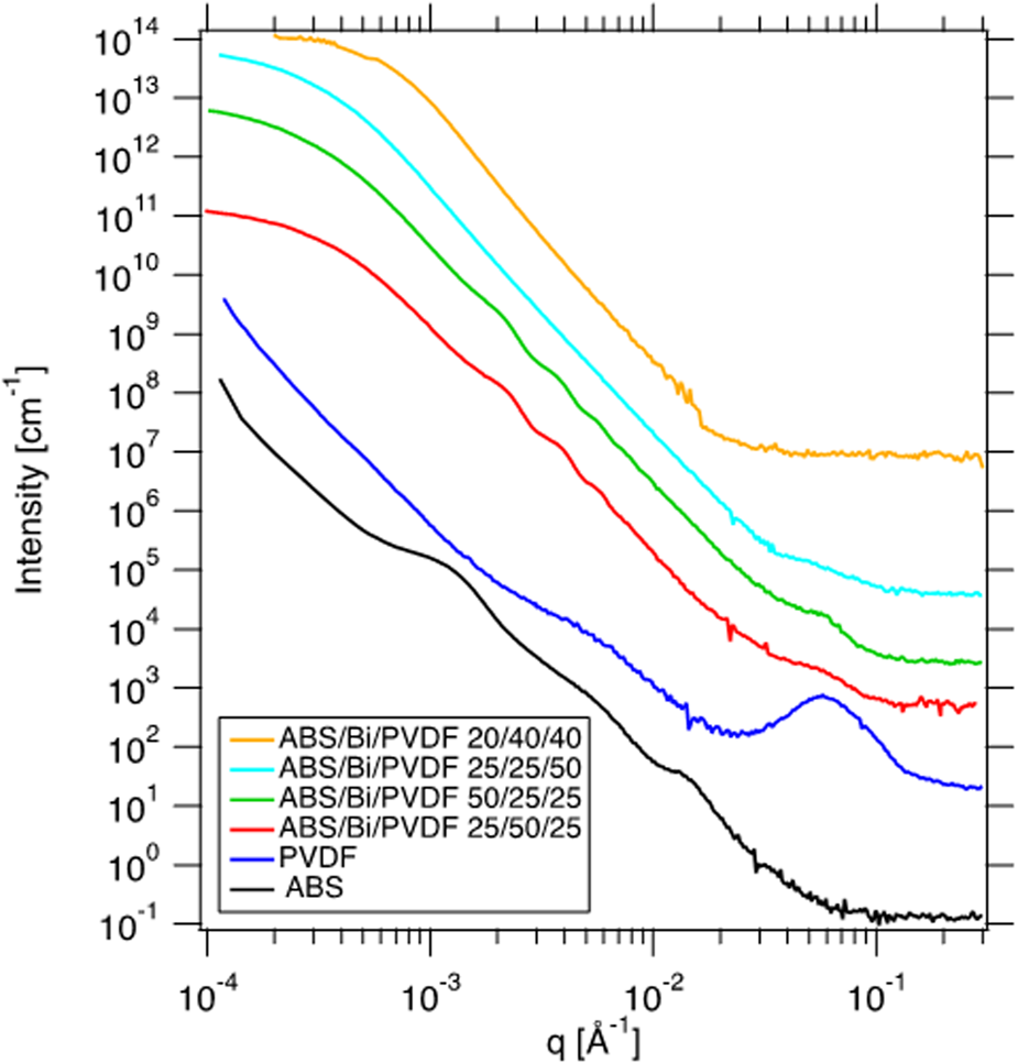
Figure 3: USAXS/SAXS profiles of ABS, PVDF, and Bi-filled composite blends. Profiles are shifted vertically for clarity.
The unified fit model was used to determine information about particle size and surface [Reference Beaucage23, Reference Beaucage and Schaefer24]. The unified fit combines scattering contributions from the size (radius) of the scattering object referred to as the Radius of Gyration R g and scattering from local, interfacial features. Interfacial scattering gives rise to power law scattering in which the exponent, P, is referred to as the Porod exponent. When P is greater than 3 and less than 4, the scattering is indicative of surface fractal scattering. For the case when P is equal to 4, scattering is attributed to a sharp, smooth interface between regions of different electron density. For P less than 3, scattering is the result of mass fractals, such as polymers in solution or polymer gels.
As shown in Fig. 3, all Bi-filled samples display a prominent Guinier “knee” scattering feature around q = 0.0004 Å−1, which corresponds to R g equal to 600–800 nm using the unified fit. This scattering feature is, therefore, attributed to the radius of the primary particle of Bi powder used in this study. The Porod exponents determined for the composite filaments in Table I approach a value of 4, such that the bismuth particles exhibit surface fractal characteristics. The variability across fit values in Table I is attributed to two parameters in the filament fabrication process that were not constrained, despite constant temperature and screw speed in the extruder: namely, lead time in the barrel of the hopper while at extrusion temperature and rate of cooling immediately following extrusion. The composite blends behaved differently in the extruder even under identical temperature and screw speeds, such that some blends took significantly longer to gravity-extrude from the barrel, and once the filament exited the nozzle, some compositions proceeded toward the water (quench) bath more rapidly than others. This variability during the fabrication process is likely due to the polymer composition and could affect bismuth crystallization and incorporation processes. Future studies will probe the origin of variation in fabrication parameters and what effect, if any, they have on metallic fillers such as bismuth. It is clear from the scattering profiles that bismuth is incorporated into the bulk material during extrusion, and that the Bi particle size reported by the manufacturer must refer to larger aggregates and agglomerates of the small, micron-sized primary particles of Bi reported in Table I.
TABLE I: Unified fit parameters extracted from scattering profiles of ABS/PVDF/Bi composite blends.

The morphology of the composites on the macroscopic scale comprises smooth and homogeneous filaments. When the scale is taken down to hundreds of microns, some filler particles become observable on the surface. Digital microscopy images at the hundreds of microns scale were taken of the printed blocks and shown in Fig. 4. In order to evaluate each material on its ability to be printed and observe distinct layers, the 3D printed blocks have some gaps between parallel components in the same layer and porosity between layers, which is seen in Fig. 4. Figs. 4(a) and 4(b) show top views of ABS and ABS/Bi 34/66 printed blocks, respectively, and Fig. 4(c) shows a side view of an ABS/Bi/PVDF 25/50/25 printed block.

Figure 4: Digital microscopy images on the order of 100 μm showing printed samples of (a) ABS, (b) ABS/Bi 34/66, and (c) ABS/Bi/PVDF 25/50/25. Each red scale bar in the bottom right of each image represents 100 μm in the horizontal direction. To evaluate the ability of each material being printed and observe distinct layers, the 3D printed parts included some gaps and porosity.
Thermal characterization
Differential scanning calorimetry (DSC) experiments were performed to evaluate heat treatment and compatibility effects on crystallization and melting behaviors of the 3D printed samples. ABS does not exhibit a true melting point since it is an amorphous polymer. Its glass transition temperature (T g) is at around 105 °C and remains unchanged when the polymer is incorporated into the composite (not shown in the DSC curves). Composites comprised of ABS and PVDF are known to phase-separate [Reference Kar, Biswas and Bose15, Reference Kar, Biswas and Bose16], so this implies that while the filament can be fabricated and 3D printed, it is not a true blend. On the other hand, Bi and PVDF exhibit endotherm and exotherm peaks, as shown in Figs. 5(a) and 5(b), respectively. It is interesting to compare the thermal behavior of Bi in the 3D printed pads with the neat Bi powder. As a reference, the onset melting point, peak melting point, and enthalpy of melting for elemental Bi are 269 °C, 272 °C, and 53 J/g, respectively [Reference Archer25]. DSC of the neat Bi powder shows two exotherm peaks, a sharp one at 241 °C, and a broader one at around 180 °C. Furthermore, a series of very small exothermic events are also observed, as shown in Fig. 5(a). The multiple exotherm peaks are likely related to crystal particle size distribution; larger particles melt and nucleate at higher temperatures than smaller metal particles [Reference Zou, Gao, Yang and Zhai26, Reference Turnbull27]. Interestingly, the sharp crystallization peak at 241 °C or the very small ones are not detected when Bi is incorporated into the ABS polymer matrix. This result indicates that the thermo-treatments used in the fabrication of filaments, as well as in the printing of the pads, altered the metal particle size distribution. Likely, the Bi powder used to fabricate our filaments contains a broad size distribution of aggregates which break up when treated to be incorporated into the polymer matrix during the feedstock fabrication process. The crystallization peak observed at around 180 °C for the neat powder is also observed at a slightly lower temperature of 176 °C for the 3D printed ABS/Bi 34/66 composite material, which indicates that the polymer network may hinder Bi particle mobility toward agglomeration. The DSC thermograms also show a sharp melting peak at 273 °C for the neat powder as well as for the composites. Thus, irrespective of the amount of incorporated bismuth in a specimen, there are no significant changes regarding to Bi melting point.

Figure 5: DSC of samples with (a) Bi and (b) PVDF.
The thermal behavior of PVDF-containing composites is shown in Fig. 6(b). Broad crystallization and melting peaks are observed for neat PVDF and for PVDF in the composites. The enthalpy of melting and thus the crystallinity of PVDF in the composites showchanges with respect to neat PVDF powder, as listed in Table II. Using Eq. (3), where the enthalpy of formation for PVDF is assumed to be  ${\Delta }H_{\rm m}^{\circ}$=104.7 J/g [Reference Marega and Marigo28] and allows for the crystallinity of the samples to be estimated. There is an increase in the percent crystallinity of the PVDF in the composite samples, which when taken with the narrowing of the melting peaks in Fig. 5(b) indicate that more uniformly sized crystals are formed when the polymer is incorporated in the polymer matrix. This change in the level of PVDF crystallinity does not affect its melting point.

Figure 6: TGA of (a) printed samples without PVDF and (b) with PVDF.
TABLE II: Melting and crystallinity of samples with PVDF.

Thermogravimetric analysis (TGA) experiments were performed to evaluate the thermal stability of the 3D printed pads. Fig. 6(a) compares the weight loss of pads containing Bi and the ABS matrix with neat ABS as the temperature increases to 600 °C. As it can be seen, the rate of decomposition is the same for the neat polymer and the composites, indicating a similar thermal degradation mechanism. In addition, the residual masses at 600 °C provide validation for the composites possessing the correct ratios of the ABS and filler material. This is because ABS will not leave any char residue even at temperatures well above the decomposition temperature (440 °C) [Reference Feng, Carpanese and Fina29], thus any remaining mass would be solely due to neat Bi. The degradation onset temperature and decomposition temperature of the neat ABS are 410 and 431 °C, respectively. Incorporation of bismuth slightly decreases the ABS degradation temperature by about 20 °C. For instance, the ABS/Bi 34/66 composite decomposes at 418 °C, instead of 431 °C. It has been observed that incorporation of metal nanoparticles, such Ni, and Pd, tends to increase the thermal stability of polymers, whereas in other instances, the opposite has also been reported [Reference Lee, Liao, Nagahata and Horiuchi30, Reference Lebedev, Gefle and Tkachenko31]. We infer that bismuth particles may help catalyze the thermal degradation of ABS.
TGA experiments were performed for the composites containing PVDF as well as for neat PVDF powder. The polymer backbone of PVDF starts to degrade at 416 °C and fully decomposes at 464 °C, as shown in Fig. 6(b). On the other hand, filaments containing both polymers, ABS and PVDF, show two distinct degradation mechanisms as readily observed in Fig. 6(b). In addition, the residual mass of thermally decomposed filaments containing PVDF includes not only bismuth but also about 15 wt% char residue [Reference Ouyang, Chen and Wu32, Reference Jiang, Xu, Wang and Chen33] from PVDF; therefore, this needs to be taken into account if TGA is used to confirm composition of such filaments. Similar to the thermal stability observed in the ABS/Bi composites, increasing the bismuth content results in a slight decrease in the degradation onset temperature. For the composite with the highest Bi amount, ABS/Bi/PVDF 25/50/25, the material starts to degrade at 394 °C, which represents an approximate decrease of 15 °C from the ABS filament.
In addition to the analysis presented above, TGA experiments were performed at different heating rates to estimate activation energy for the thermal decomposition of the composites. As expected, when the heating rate increases, the samples degrade at higher temperatures, thus the measured thermal stability increases. Using Eq. (3), the thermal activation energy slightly decreases from 11.0 kJ/mol for the filaments without Bi to 10.6 kJ/mol for the ones having the highest Bi concentration.
Mechanical properties
The results of the tensile testing for the 1.75E filaments and 0.5P, including the maximum stress and strain and Young's modulus, are listed in Table III and shown in Supplementary Fig. SI1.
TABLE III: Mechanical properties for the 1.75E and 0.5P filaments.

All the 1.75E filaments have similar maximum stress (averaging 33.2 ± 2.5 MPa) and the corresponding strain at maximum stress (averaging 3.09 ± 0.37%). In addition, all the samples possess a similar Young's modulus (averaging 2.0 ± 0.3 GPa) as well. It is interesting to notice that samples with PVDF show a significant reduction in elongation. This result is in agreement with a previous work showing that the weaker mechanical properties of PVDF reduce elongation of a PVDF/ABS composite material [Reference Kar, Biswas and Bose16]. We infer that all of the 1.75E filaments experience a necking phenomenon, where the filament gets thinner as it extends [Reference Hosford34], which is expected in thicker materials, while none of the 0.5P filaments exhibit this behavior.
The maximum stress of the neat ABS sample remains unchanged when the diameter of the filament decreases from 1.75 to 0.5 mm. However, 0.5P filament samples containing bismuth or PVDF can only withstand half as much maximum stress when compared to the corresponding 1.75E samples. This phenomena has been observed before, where thin ABS filaments exhibit greater maximum stress and strain at break than blended or composite filaments [Reference Woosley, Galehdari, Kelkar and Aravamudhan14]. The difference in mechanical response from filaments having the chemical composition but different diameters is likely due to the filament fabrication process. Because the 0.5P filaments average 600 μm in diameter, enough Bi particles at the site of the printing nozzle may impede polymer flow, causing the polymer matrix to have regions of higher or lower filler concentrations. This, in turn, weakens the overall network, which causes a decrease in the mechanical strength of filaments with the filler material. The 1.75E filaments possess a large enough diameter to make this phenomena negligible. When considering how fillers affect the maximum stress of the 0.5P filaments when compared against neat ABS, Table III shows that different concentrations of Bi and PVDF reduce the maximum stress by similar amounts (averaging a 54% and 61% change in MPa, respectively). However, there is no significant difference in the maximum stress between all the composite filaments (averaging 13.6 ± 2.0 MPa). In addition, the tensile strain at break of the 0.5P filaments are similar to each other. The samples containing PVDF do not elongate as much, which is similar to the 1.75E filament specimen. Based on these data, adding Bi significantly changes the maximum stress at break, although different concentrations do not have a considerable influence on the resulting mechanical properties. In addition, PVDF reduces the maximum elongation, which could be due to the crystallinity of the polymer making the overall composite more brittle and increasing phase separation between ABS and PVDF.
Properties of multifunctionality
A 1.2-cm-thick 3D printed pad containing 34 wt% ABS and 66 wt% Bi with a density of 1.0 g/cm3 was exposed to gamma radiation from a Cs-137 source and its shielding ability was determined by thermoluminescent dosimeter (TLD) measurements. Considering the attenuation coefficient for Bi at 0.6617 MeV to be 0.11618 cm2/g, the estimated attenuation is 13%, compared to 15% measured experimentally. A 50% attenuation of the Cs-137 gamma rays would require the 3D printed pad to have a thickness of 6 cm. For comparison purposes, a pure lead block, having a density of 11.34 g/cm3 and X-ray mass attenuation coefficient of 0.11366 cm2/g, would need to be 0.54 cm thick to shield 50% of the Cs-137 gamma rays. Although a pure lead block would be a more effective radiation shield, it poses serious and deleterious health effects. When higher-order terms in Eq. (1) are negligible and the density of a composite material is a linear combination of its constituents, Eq. (1) can readily predict radiation attenuation. However, casting composite materials and more importantly printing composite materials can lead to gaps and porosity, which results in a decreased bulk density and thus a deviation from the estimated values.
Because all the filaments contained ABS, which is soluble in the organic solvents chosen, the three samples, ABS, ABS/Bi 56/44, and ABS/Bi/PVDF 50/25/25, readily dissolved in their vials. It should be noted that for every solvent, which includes xylene, toluene, and chloroform, the filament containing PVDF took longer to show initial signs of dissolution, such as swelling and partial disintegration. Specifically, in chloroform, the ABS and ABS/Bi 56/44 samples exhibited many pieces peeling off the filaments after 10 min, while it took 20 min for the ABS/Bi/PVDF 50/25/25 samples to exhibit the same phenomenon. Furthermore, after 20 min, the ABS was completely dissolved, whereas the solution containing the ABS/Bi 56/44 was opaque and black, while the solution containing the ABS/Bi/PVDF 50/25/25 was much clearer. With regards to using these multifunctional filaments in extreme environments where harsh solvents would be present, the ABS/Bi/PVDF 50/25/25 filament was observed to possess a greater chemical resistance because it showed signs of partial dissolution after twice as much time had elapsed.
Conclusions
In this work, multifunctional ABS-composite filaments were successfully fabricated using a solvent treatment, where the Bi filler and PVDF polymer were incorporated homogeneously as confirmed by FTIR and MXRF. Thermal properties of the filaments were investigated to evaluate the phase transformations, percent crystallinity, and thermal stability. The thermal analyses showed that the glass transition of 105 °C for ABS did not change for the composites, increasing the filler amount increased the PVDF crystallinity, and the thermal stability decreased for the samples with the most Bi concentration, where composites with and without PVDF showed a reduction of 20 and 15 °C, respectively. Mechanical testing showed that adding Bi filler reduces the maximum engineered stress of the filaments, but that increasing the Bi concentration did not further significantly modify the mechanical strength. Radiation attenuation data proved that these composites can shield against incident gamma rays and that the polymer did not degrade. Printing with fewer gaps, thereby reducing the porosity, will effectively increase the bulk density of the printed parts and shield radiation to a greater extent. Testing the chemical resistance against organic solvents showed that filaments containing PVDF exhibited signs of partial dissolution after twice as much time had elapsed when compared to filaments without PVDF.
Materials and methods
Materials
ABS was supplied from Filabot (Barre, VT). Extruder Purges E and NF were supplied from Asaclean (Parsippany, NJ). Acetone was supplied from Sigma-Aldrich (St. Louis, MO). Bismuth powder was supplied by Alfa Aesar (Haverhill, MA) and is from a sieve designation of No. 325, which correlates to particles sizes of 44 μm. PVDF powder was supplied from Aldrich Chemistry (Milwaukee, WI). Chloroform, xylene, and toluene were supplied by Thermo Fisher Scientific (Waltham, MA). Proton nuclear magnetic resonance (1H-NMR) was performed on the received ABS dissolved in deuterated acetone to estimate ABS chemical composition. It was found to be nominally comprised of 17% acrylonitrile, 20% butadiene, and 63% styrene.
Feedstock and filament fabrication
A ratio of 1:4 w/w ABS to acetone was combined and manually stirred before being placed in a temperature-controlled oven at 50 °C for 6 h to ensure the complete dissolution of ABS. The Bi metal filler and PVDF polymer were then added to the ABS solution. ABS composites with Bi and PVDF were made in ratios up to 66 wt% added content (Bi and/or PVDF added). All composite ratios herein are reported on a total wt% basis. To prevent the solution from becoming too viscous for adequate mixing, acetone was added in 5 mL increments while manually stirring. After stirring, the solution was placed in a planetary mixer for 2 min at 2000 rpm at a vacuum of 17.6 kPa. The resulting slurry was poured into a high surface area to volume ratio mold and remained in a fume hood for 24 h to evaporate any surface-level solvent. This allowed the sample to harden enough to be cut into approximate 1 cm × 1 cm pieces. The small fragments were stored in a vacuum oven at 50 °C for another 24 h to remove residual sub-surface solvent. Following solvent removal, a Filabot EX2 extruder equipped with a 1.75-mm-diameter extruder nozzle was heated to 215 °C. A room temperature DI water bath was placed below the extruder nozzle such that the resulting filament was gravity fed into the cooling bath to facilitate solidification. Extruder Purges E and NF were used to flush out the extruder system before and after each feedstock material was fed into the hopper. The screw speed was set to its maximum setting, producing 2 lbs/h.
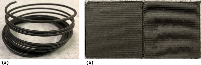
A Hyrel MK-1 250 modular printing head with a 500-μm nozzle diameter was attached to a Hyrel System 30M and heated up to 240 °C while the heating bed within the system was heated up to 90 °C. Composite filaments were fed into the modular printing head and extruded onto the heating bed at a rate of 1800.00 mm/min and according to designs made on the Solidworks software. Composite feedstock materials were successfully fabricated and used for printing. An ABS/Bi composite extruded into a filament and printed into blocks is shown in Fig. 7.

Figure 7: ABS/Bi (a) filament and (b) printed pads.
Gamma irradiation
A 3D printed pad consisting of 34 wt% ABS and 66 wt% Bi was exposed to gamma irradiation from a Cs-137 source located at Sandia National Laboratories (Albuquerque, NM). The accumulated gamma dose was determined from TLDs-700 that were placed on the back of the 3D printed pad. The final gamma dose was 75 Gy at 0.28 Gy/h. The experimental attenuation value is compared with the estimated one provided by the Beer–Lambert Law [Reference El-Kateb, Rizk and Abdul-Kader35, Reference Canel, Korkut and Korkut36, Reference Bashter37, Reference Zinkle and Was38]:
 $$I\approx I_0e^{-{\rm \mu \rho} t}$$
where I is the outgoing intensity of radiation, I 0 is the incident radiation, μ is the attenuation coefficient, ρ is the density of the material, and t is the thickness of the material.
Characterization techniques
FTIR was performed on a Thermo Fisher Scientific Nicolet iS20 FTIR Spectrometer (Waltham, MA) with a range from 525 to 4000 cm−1. Background data were collected before each sample and 32 runs were performed per sample pre- and post-irradiation. Digital microscopy utilized a Keyence VHX-6000 (Itasca, IL), where high-resolution microscopic images were taken of the samples pre- and post-irradiation. MXRF measurements were performed using a Bruker M4 Tornado Micro-XRF (Billerica, MA) with acquisition parameters being an X-ray tube operating at 50 kV and 200 μA, a spectrometer operating at 40 keV and 130 kcps, vacuum (20 mbar), 20 μm spot size, 20 ms per pixel dwell time, and 10 μm (cross section) to 20 μm (top down) step size. Spectra and mapping were compiled for the printed specimen before and after being irradiated. USAXS/SAXS measurements were collected at beamline 9-ID-C at the Advanced Photon Source (APS) at Argonne National Laboratory (Lemont, IL) [Reference Ilavsky, Jemian, Allen, Zhang, Levine and Long39]. SAXS profiles were reduced using the Indra and Nika programs for Igor Pro [Reference Ilavsky40]. The Irena program for Igor Pro was used to merge same specimen USAXS and SAXS as well as analyze the data [Reference Ilavsky and Jemian41].
Thermal properties were investigated via DSC (TA Instruments DSC Q20 series (New Castle, DE)) and TGA (TA Instruments TGA Q2000 series (New Castle, DE)). DSC allows for the determination of phase transformations and percent crystallinity. This is important because the feasibility and usefulness of a printed part heavily relies on its mechanical properties, which are in turn influenced by its thermal properties. Specifically, a material's crystal domains affect the overall brittleness and elongation [Reference Temenoff and Mikos42], thus determining the composite materials’ crystallinity will assist in understanding their mechanical properties. To ensure the samples have identical thermal history, only the second heating cycle from DSC were analyzed. All of the samples were from printed parts and had a mass ranging from 10 to 20 mg. The samples were run under nitrogen at a flow rate of 5 mL/min and were heated from room temperature (25 °C) to 300 °C at a rate of 10 °C/min, held at 300°C for 1 min, cooled to 25 °C at a rate of 10 °C/min, held at 25 °C for 1 min, and the entire process was repeated once more. Calculating percent crystallinity %Χ c of a polymer composite uses Eq. (2) [Reference Kessler43, Reference Gray44]. It relates the percent crystallinity to the enthalpy of melting ΔH m, the enthalpy of formation $\;{\rm \Delta }H_{\rm m}^ {\circ}$, and the weight fraction W p of the polymer component of interest. The enthalpy of melting is obtained by integrating the endothermic melting peak of a DSC curve.
 $${\rm \percnt }{X}_{\rm c} = \displaystyle{{{\Delta }H_{\rm m}} \over {{\Delta }H_{\rm m}^{\circ} W_{\rm p}}}$$
TGA allows for the determination of thermal stability of a material. For TGA, all of the samples were from printed parts and had a mass of 15 ± 1 mg. The samples were run under nitrogen at a flow rate of 10 mL/min and were heated from room temperature (25 °C) to 600 °C at heating rates of 5, 8, 10, 13, and 15 °C/min. TGA experiments were run three times for each sample at the heating rate of 10 °C/min. The composite materials’ degradation onset and decomposition temperatures are able to be determined by measuring the mass percent of each sample at the same percent conversion (X = 95%) and the respective maximums of their derivative curves. The activation energy E a of thermal decomposition for the printed samples is calculated from the rate-dependent thermal stability using the Coats–Redfern equation [Reference Lu, Lee, Chen and Lin45], shown in the following equation:
 $$\ln \left({\displaystyle{{-\ln \lpar {1-X} \rpar } \over {T^2}}} \right) = \ln \left({\displaystyle{{AR} \over {{\rm \beta} E_{\rm a}}}} \right)-\displaystyle{{E_{\rm a}} \over {RT}}$$
It is in the form of a linear equation relating the percent conversion X and temperature T in Kelvin against the inverse temperature. The resulting slope includes the activation energy and the universal gas constant R and the resulting y-intercept includes a frequency factor A, the universal gas constant, the activation energy, and the heating rate β.
Chemical resistance to solvents was tested on ABS-composites filaments with and without PVDF. The chosen specimens were ABS, ABS/Bi 56/44, and ABS/Bi/PVDF 50/25/25. Filament samples were placed in vials containing a solvent. The solvents included xylene, toluene, and chloroform. Upon placing the filaments in the vials with a solvent, the time was recorded to determine how long it took for dissolution to occur.
Mechanical testing was performed on an Instron 4340B (Norwood, MA), where 10 cm filaments of each composite were placed in the instrument for tensile testing. Two types of filaments from each composite were tested: those obtained from the extruder with a nozzle diameter of 1.75 mm (referred to as 1.75E) and those obtained from the 3D printer with a nozzle diameter of 500 μm (referred to as 0.5P). To make 0.5P filaments, 1.75E filaments were put through the 3D printer, but no design was specified, thus providing default thin cylindrical wires. The 0.5P filaments had an average diameter of 600 μm. Every type of filament was placed in a configuration where the grippers of the tensile tester were separated by 3.5 cm and pulled apart at a rate of 0.5 mm/min. Before the tensile test, the diameter of each filament was measured with calipers at each end and the middle, where the resulting average was input into the mechanical testing software. The printed and extruded filaments for each listed composition were tested with at least four samples each and the reported values are derived from the calculated average and standard deviation.
Acknowledgments
This work was performed under the U.S. Department of Energy's National Nuclear Security Administration Contract No. DE-AC52-06NA25396. This research used resources of the Advanced Photon Source, the U.S. Department of Energy (DOE) Office of Science User Facility operated for the DOE Office of Science by Argonne National Laboratory under Contract No. DE-AC02-06CH11357. USAXS/SAXS data were collected on the 9-ID-C beamline at the APS, Argonne National Laboratory under General User Proposal number 64333. The authors thank Adam Pacheco for his technical support during this project.
Supplementary material
To view supplementary material for this article, please visit https://doi.org/10.1557/jmr.2020.118.


 Open access