


Work in glaciology calls more and more for varied drilling processes adapted to the study undertaken, to the depths to be reached, to the logistic circumstances, and to the glacial zone in which the work is being done. This is what has led the Laboratoire de Glaciologie to develop several drilling processes, the essential characteristics of which we would like to summarize here.
1. Steam drilling
Several versions of this procedure currently exist (Reference HodgeHodge, 1971; Reference HoworkaHoworka, 1965). In fact, the Laboratoire de Glaciologie after using a hot-water drill (Reference KasserKasser, 1960) developed its first steam-operated ice drill in 1966 (Reference GilletGillet, unpublished). Up till now, this method has been used especially for making holes 10–15 m deep intended for the reception of ablation stakes. A boiler consisting of four connected vertical tubes is heated by a propane burner that consumes x kg of gas per hour. The steam produced is sent to a drill tip with an outside diameter of 32 mm which injects it directly against the ice (Fig. 1). The total weight is:


Fig. 1. Schematic illustration of steam-operated ice drill: 1—pump, 2—burner, 3—manometer, 4—safety valve, 5—double- walled flexible hose, 6—propane tank, 7—straight guide tube, 8—water.
The equipment is therefore easy to carry. Its penetration speed is 30–40 m/h for the first 10 m, 20 m/h for the next ten. (With a more powerful burner it would be possible to increase the drilling speed. However, this would lead to an increase in the size of the boiler and the diameter of the hoses. The material would then be difficult to carry). The speed remains constant in ice charged with sandy debris. The global efficiency, the relation between the heat needed to make a 32 mm hole, and the heat furnished by the propane is about 23% at close to 40 m/h.
The steam operated drill works in all climates (even in strong winds) and at all altitudes. In particular the production of water from snow is assured in a double jacket, which allows drilling in accumulation zones and when water is not available on the glacier surface. When it is needed, water can be injected with a small hand pump. Recently, we drilled to a depth of 30—40 m. Pressures and temperatures close to 4 bars and 150°C must then be accounted for. It was necessary moreover to properly insulate the soft hoses that carry the steam. In fact with an insulation made only of two concentric hoses, the “on-line losses” are rather large and the speed decreases sharply with the depth. This is why we have replaced the outer hose with a soft closed-cell insulation.
II. Hot-water drilling (Reference Reynaud and CourdouanReynaud and Courdouan, 1962)
A motor pumps a strong stream of water (1–2 m3/h) into a boiler consisting of a coil and a propane burner that consumes 2.5kg of gas per hour (which corresponds approximately to 28 kW). The water is heated in this way to approximately 15° C and is pumped directly to the bottom of the drill hole. While coming back up to the surface (except in the rare cases when the water drains into the glacier) it cools widening the hole, before being taken back in by the pump (Fig. 2), PVC hose can be used (diameter 20–26 mm).
The weight is:


Fig. 2. Schematic illustration of hot-water ice drill: 1—pump, 2—manometer, 3—boiler, 4—burner, 5—propane tank, 6—single-walled flexible hose, 7—straight guide tube.
For drilling between 50 and 120 m, on the average, one tank of propane is consumed for every 55 m drilled. A tank of propane weighs 26 kg and contains 13 kg of gas. The fuel is thus by far the heaviest weight. All this equipment however is easily portable. To increase the speed two boilers can be placed in series. The penetration speed for the first few metres then increases from 15–20 m/h to 20–30 m/h. The speed decreases slowly as you go deeper. To illustrate this, we offer the results of several drillings carried out during the summer of 1972 on the Glacier de St-Sorlin at 2 700 m (Fig. 3).

Fig. 3. Drilling curves in ice obtained in the field for hot-water drilling and electrical drilling. Note that the scales used for time are not the same.
We used this process easily down to 120 m. At that depth, it was already necessary to use a rather long (4 m) and heavy, rigid tube, to really “sense” what was happening at the bottom, and to obtain vertical drilling. It is possible to drill deeper. This would require the installation of a device that could tell if the rigid tube is resting on the bottom of the hole. A good part of the warm water’s heat is given up to the ice when the water is brought back up to the surface, so a very conical hole is obtained. With a 40 mm diameter borer the diameter reaches 70 mm at a depth of several meters, and at the surface varies from, on an average, 120–150 mm.
Advantages of this process
-
(a) Very deep holes with rather large diameters can be drilled with light and simple equipment that can be operated by one person.
-
(b) It is extremely secure and reliable (risks of breakdowns very small, jams non-existent).
-
(c) The jet of water cleans the bottom of the hole so it is possible to drill in ice charged with sand or silt.
Inconveniences
-
(a) The hole is rather irregular. It is difficult, therefore, to use for certain measurements (closure of the bore hole, inclinometry).
-
(b) It is impossible to drill when there is no water on the surface. Indeed a minimum of water is indispensable to prepare the circuits and compensate for losses that can occur. This kind of drilling, therefore, is unusable in accumulation zones and is difficult to use in a very crevassed zone. Prolonged periods of frost can also cause the loss of a lot of time.
-
(c) If the water empties from the hole, which sometimes happens when you approach the bottom of the glacier, the drilling becomes difficult. In fact, in air, the apparent weight of the full hose becomes significant and you can no longer feel if the rigid guide tube is resting on the bottom. In such a case, it is absolutely impossible to control the verticality of the drilling.
III. Electrical drilling
We have seen that steam drilling allows us to drill in any glacial zone to a depth of about 30 m. Hot-water drilling is only usable in an ablation zone during the summer. With it, we can drill to average depths (100–150 m) but the holes we obtain are extremely conical and have rather irregular sections. Whenever we want to drill deeper than 30 m in an accumulation zone, or beyond 150 m in an ablation zone, or obtain deep holes with regular sections, we must resort to electrical drilling. Apart from the references mentioned in the text, the bibliography at the end of this article contains a number of other references concerning electro-thermal drills.
Functioning principle
A drill head heated electrically by the Joule effect is supplied with energy coming along an electric cable from a generator. As in all drilling problems, the problem is the transportation of energy from the surface of the glacier to the bottom of the hole. Unlike heat, electrical energy is easy to transport over large distances, so several hundred metres can be reached without difficulty. On the other hand, the production of electrical energy is an expensive and heavy operation compared to a gas burner and a boiler. It is therefore immediately apparent that this solution is only advantageous for drilling holes with small diameters. Theoretically the drilling speed V (in m/h) is related to the power supplied W (in W) by the area (in cm2) S of the cross-section of the drill by the equation:
Thus, a drill with a diameter of 18 mm furnishing 400W, could advance 18.4 m/h. In practice, an appreciably greater power must be supplied because some of the heat only serves to widen the hole. This is due to lateral losses and, above all, to strong convection currents produced at the level of the “working face” that result in a significant transfer of heat towards the top. The curve (Fig. 4) experimentally obtained for an 18 mm drill head allows us to estimate the losses that result, as well as to calculate the efficiency of the drill as being the ratio of the true speed to the theoretical speed. It is 55% for 400W and 49% for 800W. These figures also represent the ratio between the surfaces of the cross-section of the drill and of the hole. For example, for 800W the diameter of the drilled hole will be 25.6 mm whereas the drill is 18 mm:

Fig. 4. Drilling curve obtained in laboratory tests with an electrical drill (diameter 18 mm). Drilling rate is plotted as a function of power density on the heating head.
Design
In order to obtain a large power density on the heating head with a sufficient operating lifetime (Reference Shreve and SharpShreve and Sharp, 1970, p. 69–70), we used a technique perfected by the Commissariat à l’Energie Atomique (Reference TeytuTeytu, 1971), that is casting the heating elements in silver. These heating elements are made of a nickel-chrome wire covered by a flexible stainless-steel tube and insulated with compacted magnesia. The casting of the silver is done in vacuum to guarantee a perfect thermal contact between the heating element and the silver without any gas bubbles or inclusions. The advantage of this procedure is that it allows the fabrication of heating heads with long life spans even if used with high thermal flux (these reaching regularly 250 to 300 W/cm2 of cross-section). A thermal probe placed in the silver makes it possible to measure the temperature of the head and to reduce the heat if the thermal exchanges are not being properly made, in particular because of a lack of water (when working in a crevasse or drilling in the snow).
We have built:
-
(a) A drill 18 mm in diameter operated with a monophase voltage varying from 0 to 220V which with a 1.5 kW generator makes up an easily portable outfit for measuring the thickness of glaciers.
-
(b) A 45 mm drill supplied with a three-phase 380 V supply for drilling holes which are intended for measuring the deformation of the ice with an inclinometer. On the top of the drill is a device which controls the force with which the head pushes against the bottom of the hole. The drill is suspended from the cable by a spring. A magnetic mass firmly joined to the drill acts upon two magnetic micro-relays which correspond to the high point and the low point of the spring’s normal working zone. The information is transmitted to the surface by the cable. A heating resistance is placed at the top of the drill to be used in case of jamming on the way back up. The diagram (Fig. 5) gives the form of the 18 mm in diameter silver head that is used. When working in this way with high power densities, one must use a shape providing a thermal flux that is as homogeneous as possible (Reference StaceyStacey, 1960). Otherwise after a certain power density is reached, one notices that the speed barely increases with an increase in power. With the last model that was perfected for an 18 mm head, after numerous trials (Fig. 6), we were able to vary the speed with the power linearly, up to a flow of 325 W/cm2 (no tests having been made beyond that).
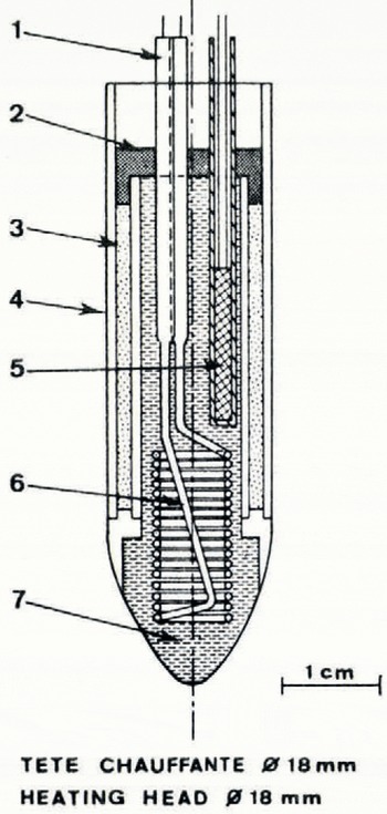
Fig. 5. Heating head. High thermal flux is allowed because of casting silver around the heating wire. 1—cold end of the heating wire, 2—resin, 3—insulating powder, 4—tube, diameter 17–18 mm, 5—thermal probe, 6—heating wire, 7—silver.

Fig. 6. The shape of the last heating head, used in 1973, gives a linear variation of the speed with the power density up to a flow of 325 W/cm 2.
Results obtained
The curve given (Fig. 4) shows that with the 18 mm drill we were able to obtain a speed of 18.6 m/h in pure ice for a power density of 325 W/cm2 of cross-section. During the spring of 1973, numerous drillings were done on the Mer de Glace and the glaciers of the Sommet de Bellecôte. The speed obtained there was appreciably lower than in pure ice. We obtained in the Bellecôte glaciers an average speed of 12 m/h with 650 W of power on the head. For the same power the laboratory tests gave almost 15 m/h.
When drilling in a glacier, one also notices that at times the speed decreases very sharply for a few centimetres or decimetres. Might this be explained by the existence of layers of ice full of solid debris? On the Mer de Glace in a place where the bed-rock was reached at 180 m, this phenomenon was observed at 60 m and was so strong that we believed for a moment that we had reached the bed-rock.
Acknowledgements
I would like to thank all those at the Laboratoire de Glaciologie who have worked toward the development of these materials and in particular M. Claude Rado, whose contribution to the development of the electrical drilling process was particularly important.


