


Introduction
To predict ice forces on a narrow vertical pier requires an understanding of how ice fails in crushing.
An empirical correlation for ice crushing against a vertical pier was developed by Reference KorzhavinKorzhavin (1962):
where p is the ice pressure across diameter of pier and ice thickness, I the indentation factor which accounts for the relative geometry of the system. I is defined as being equal to 1.0 for a wide pier and about 2.5 for a narrow pier, m is the shape factor (equal to 1.0 for a flat face and 0.9 for a round face), k the contact factor (1.0 for perfect contact), and σ the compressive strength of ice.
It is believed that the above relationship reflects all the vital components of the process of ice action on vertical piers. However, its usefulness is limited because of the need to specify a value for ice strength (σ). It is well known that values for ice compressive strength can vary widely depending on ice type, temperature, strain-rate, size of sample and method of testing.
The aim of the work described in this paper was to perform controlled field and laboratory tests in order to investigate the relationship between small-scale ice strength and maximum ice forces on vertical piers. The incentive behind the study was the need to provide a sound basis for deriving design criteria for offshore platforms for oil exploration in the Beaufort Sea where there are no precedents for the design of ice-resistant structures.
The strategy for the work consisted of three independent, but related activities:
(a) Field tests in which a flat indentor was pushed against a natural ice sheet using special equipment. These tests simulated the action of a moving ice sheet against a narrow vertical face. By using a flat indentor in good initial contact with the ice, it was believed that the terms m and k in Korzhavin’s equation would be unity.
(b) Laboratory tests on ice taken from the field test sites were conducted for a range of strain-rate and temperature. (These tests were actually extended to include ice taken from other locations.)
(c) The derivation of theoretical models based on plasticity theory, to try and relate the data from the laboratory and field tests. In other words, to derive a theoretical relation for I in Korzhavin’s equation and compare it with apparent values derived from measurements.
This paper describes these activities and discusses the results.
The Field Tests
Prior to conducting these tests, we had already performed similar crushing tests in the Arctic at Tuktoyaktuk (Reference Croasdale, Reed and SaterCroasdale, 1974). These Arctic tests, in which ice moving against a vertical pier was simulated by pushing a pier through the ice, were successful but awkward to conduct. Only one or two data points per year could be obtained and it became obvious that a speedier field test technique was desirable.
Equipment and Location
The redesigned equipment was again based on the principle of pushing an indentor through the ice to simulate the action of ice against a pier (Fig. 1). The flat indentor was 0.75 m wide by 1.0 m high and was pushed through the ice by means of four hydraulic rams acting against a reaction face 1.25 m wide by 1.0 m high. Each hydraulic ram had a stroke of 0.3 m and a load capacity of 1.7 MN. The rams were actuated by a common hydraulic supply by means of a gasoline-powered pump; they were synchronized by the structural rigidity of the loading faces. The equipment which weighed 1 500 kg was portable and could be lowered into a pre-cut hole in the ice by means of a lifting frame which could be skidded from one test site to another.

Fig. 1. The field test equipment.
Most of the tests were conducted on ice about 0.75 m thick and chain saws were used to cut the test holes. Potentiometers to record the motion of the indentor were clamped between the loading faces and also fixed between the faces and the ice. Continuous recordings of these motions in addition to the hydraulic pressure supplied to the rams were taken during each test. The average ice pressure across the indentor was derived by dividing the applied load by the area of the indentor in contact with the ice sheet.
The temperatures of the air and the ice were measured before each test. After a test, the geometry of the failure surfaces was measured and ice was collected for small-scale testing and crystal examinations at the University of Alberta. Lastly, the hole was fenced-off to prevent weekend snow-mobilers from falling into the lake! The test site was on Eagle Lake, a shallow irrigation lake on the prairies about 48 km east of Calgary. A whole test operation, including travelling from Calgary and cutting a test hole could be undertaken easily in one day.
The Scope of the Tests
The field program was conducted during the period 27 January to 10 March 1971, and a total of 27 tests were performed. The specific objectives for the field tests were:
(i) to investigate ice crushing pressure for a range of strain-rates and ice thickness,
(ii) to document modes of ice failure,
(iii) to compare the measured ice pressures with the compressive strength of ice.
During the test program, the natural ice cover on the lake grew in thickness from 74 to 99 cm and all but three of the tests were in this ice. To perform tests on thinner ice required the cutting of test ponds, which were cleared in late January and allowed to refreeze to about 20 cm before being tested. The ponds were about 4.5 m × 4.5 m, a size which was considered large enough to eliminate the “edge effects” from the surrounding thicker ice.
In the tests, the only controlled variable was the rate of supply of hydraulic fluid to the rams, by which means a variation in loading rate or strain-rate could be achieved.
A nominal strain-rate can be defined as the average velocity of the indentor to failure divided by an appropriate length such as the width of the indentor or the ice thickness. For the results presented in this paper, strain-rate is defined in terms of indentor width. In the main test series, strain-rates as defined above were in the range 7 × 10⁻⁵ to 4.4 × 10⁻³ s-1.
By the start of the test program, we had already developed the analytical model described later in the paper. This model indicated that the friction between the indentor and the ice would affect the ice crushing pressure; the extreme case being when the ice was frozen to the indentor. In order to provide additional insight into this aspect of the analytical model, we planned two tests in which the indentor was allowed to freeze to the ice sheet. We also performed two other tests in which the ice was slotted to form large in situ unconfined specimens.
Results of the Field Tests
As shown by the typical recorder traces in Figure 2, the pressure applied to the ice increased to a peak value at which the ice failed. After initial failure, the ice pressure usually fell to about half the peak before rising again. The limited stroke of the equipment (30 cm) prevented a second peak from being realized.
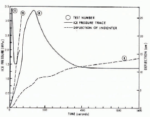
Fig. 2. Typical recorder traces for slow and fast field tests.
The failure mode witnessed during the main test series can be described as flaking and is shown in Figure 3. The failure was of a double-wedge type as derived in the upper-bound solution described later in this paper. The actual geometry of the failure varied little from test to test. A typical failure had a wedge angle in the range 40° to 45° from the horizontal.

Fig. 3. Typical failure mode in the field tests.
A summary of results of all 27 tests is given in Table I.
TABLE I. EAGLE LAKE ICE TEST RESULTS 1971

The Laboratory Tests
The tests described in this section were actually conducted on ice from various sources. A total of 113 unconfined compression tests were performed; 60 tests were on ice grown in the cold room, 29 were on ice taken from rivers near Edmonton, 5 on ice from Tuktoyaktuk Harbour and 19 tests were on ice taken from the sites on Eagle Lake at which the indentation tests were performed. Initially, unconfined samples 15 cm × 15 cm × 30 cm were tested but this size was reduced to 10 cm × 10 cm × 20 cm because of load capacity limitations of the test machine. In addition to the unconfined tests, 28 confined or plane-strain tests were performed, these tests were on ice 6 cm × 15 cm × 30 cm in size.
Equipment and Test Procedures
Samples were prepared and tests conducted in a cold room at the University of Alberta. A Wykeham Ferrance 10 ton compression testing machine was used for all tests. Strain-rate was not deduced from the platen speed but measured independently by two linearly variable differential transformers (LVDT’s) placed on each side of the specimen.
Samples were milled and loading faces were machined just prior to sample testing. Steel test platens and spherical platen seats were made in accordance with the recommendation of Reference Hawkes and MellorHawkes and Mellor (1970). In the confined tests, transverse restraint was applied by means of two steel plates 2.2 cm thick connected by 16 steel bolts (2.5 cm diameter). It was estimated that transverse strain was less than 1% of principal strain.
In all tests, the load was applied in the plane of the natural ice sheet, that is, at right angles to the columnar axes of the crystals. Tests were performed at two temperatures, —10°C and —1.5°C.
Results of the Laboratory Tests
Compressive strength values for horizontal c-axis ice are plotted against strain-rate in Figure 4 for —10°C, and in Figure 5 for —1.5°C. The effect of strain-rate is most obvious in the tests conducted at —10°C. At this temperature, the tests indicate a maximum unconfined compressive strength of about 7.6 MPa at a strain-rate of about 10-4 s-1 The confined strengths are greater, with a maximum of 16.6 MPa at the maximum strain-rate tested. At —1.5°C, there is more scatter but still an indication of strain-rate dependence. The warmer ice is weaker with a peak unconfined strength of 2.9 MPa and a confined strength of 11.5 MPa.

Fig. 4. Laboratory compressive strengths for ice with horizontal c-axes at —10°C.

Fig. 5. (left). Laboratory compressive strengths for ice with horizontal c-axes at —1.5°C.
The Eagle Lake ice was tested only in the unconfined mode and at one temperature —1.5°C (see Fig. 6). There is considerable scatter in the data perhaps because of the much larger crystals, which in some cases were as large as the width of the test blocks. The strength appeared to vary with the test location.

Fig. 6. (right). Laboratory compressive strengths at —1.5°C for ice taken from the field test sites.
Theoretical Analysis of Ice Pressure
The theoretical solutions were aimed at providing a relationship between basic ice strength properties and indentor-type field tests.
Idealization of Ice Properties and Yield Criterion
We assume ice to be an isotropic, homogeneous ideal elastic-plastic material. Yielding is governed by a relation between the principal stresses known as the yield criterion.
It will be assumed in this analysis that ice behaves like most metals and that yielding is independent of hydrostatic pressure. In this case, the simple Tresca yield condition can be applied, which states:
where σ1 denotes the major principal stress, σ2 denotes the minor principal stress and q denotes the shear strength, and it follows that
where σ is the uniaxial compressive strength. Equation (2) states that yield occurs when the greatest shear stress on any plane has reached a limiting value.
Plasticity Analysis
The penetration of an ice sheet by a flat indentor can be analysed by the Lower- and Upper-Bound Theorems of plasticity (Reference Prager and HodgePrager and Hodge, 1951, or Reference CalladineCalladine, 1969).
The Lower-Bound Theorem states the following: If any stress distribution throughout the loaded body can be found which is everywhere in equilibrium internally and balances the externally applied loads and at the same time does not violate the yield condition, those loads will be carried safely by the body.
The Upper-Bound Theorem is as follows: If an estimate of the plastic collapse load of a body is made by equating internal rate of dissipation of energy to the rate at which external forces do work in any postulated mechanism of deformation of the body, the estimate will be either high or correct.
It should be noted that neither the stress distribution in the first case nor the mechanism of deformation in the second need be the correct ones. The true solution is found when both upper and lower bounds converge to the same result. When they do not, the true solution will be between the lowest “upper bound” and the highest “lower bound”.
The problem of interpreting the indentation tests is one of computing the resistance offered to incipient indentation of a pier or indentor by the edge of the ice sheet. (In all the indentation tests, a tensile crack first forms at right angles to the direction of loading, so that subsequent crushing failure of the ice sheet is the same as would occur due to edge loading of a thick plate, see Figure 7.)

Fig. 7. Geometry of fiat indentor.
We can define the solution in the form,
where σ denotes the compressive strength of the ice, p denotes the average pressure on the indentor at failure and I is the indentation factor which will depend on the geometry of the indentor, the ice thickness and the boundary conditions.
To solve for I is the objective of this analysis, and solutions are derived for two boundary conditions; first with the ice free to slip at the face of the indentor, and second with the ice frozen to the indentor.
Smooth Flat Indentor
The geometry of the arrangement is defined in Figure 7; d is the width of the indentor and t is the ice thickness. When d is much smaller than t, the problem reduces to the classical Prandtl indentor for which there is an exact solution,
therefore
Also when d is much larger than t, the lower-bound solution shown in Figure 8 becomes exact, i.e.
therefore
Between these limits, the problem is three-dimensional and I will depend on the ratio of d/t which is sometimes called the aspect ratio. An upper bound solution for this problem will now be derived.

Fig. 8. Lower-bound solution.
Two kinematically admissible velocity fields are shown in Figure 9. It can be shown that “solution I” gives a lower upper bound (Reference Morgenslern and NuttallMorgenstern and Nuttall, unpublished). We will work through one case for d/t=1.0. The indentor moves with velocity V and external work D e is

Fig. 9. Upper-bound velocity fields.
Internal dissipation due to shearing resistance q occurs along the velocity discontinuity surfaces such as (abde), (bed), (afe). If the wedges are inclined at θ to the edge of the ice sheet, from symmetry the energy dissipated internally D i is
Equating De and Di, we get
To find the critical inclination, we put
which gives θ = 41° and
i.e. I = 1.34.
This calculation can be repeated for several values of d/t to give the curve shown in Figure 10.

Fig. 10. Theoretical solutions.
Rough Flat Indenlor
If there is adhesion between the interface and the ice sheet, more dissipation of energy takes place internally due to shearing resistance at the interface. Any value of shearing resistance could be assumed at the interface up to the limiting value of q the shear strength of the ice. In this case, accounting for the extra resistance, the solution becomes,
Following minimization with respect to θ, the critical values of p/σ may be found for the range of d/t of interest. Again there is a plane-strain cut-off at d/t = 0. The size-effect curve for the rough indentor is also shown in Figure 10.
Solutions can also be found for circular indentors using the same technique (Reference Morgenslern and NuttallMorgenstern and Nuttall, unpublished) but these will not be discussed here.
Discussion
As can be seen in Table I, the field ice pressures show no obvious trend with variations in strain-rate over the range tested. For example, the lowest ice pressure of 2.5 MPa was obtained at a strain-rate of 1.8 × 10⁻⁴ s-1 yet one of the highest ice pressures of 4.83 MPa was obtained for a similar strain-rate (2.9 × 10⁻⁴ s-1). In contrast the laboratory tests show a fairly obvious strain-rate effect, with lower strengths being obtained at lower strain-rates (Figs 4 and 5). Presumably lower field ice pressures might have been obtained had lower strain-rates been tested.
Temperatures could not be controlled during the field tests, but ice surface temperatures varied in the range —18°C to —7.4°C. However, as can be seen from Table I, there was no obvious effect of temperature. In fact, some of the highest crushing pressures were obtained with relatively warm ice. For example, a value of 4.83 MPa was obtained at a surface temperature of —2.5°C whereas at —18°C, the crushing pressure was 3.33 MPa. The laboratory tests, however, did show a temperature effect, with higher crushing strengths at —10°C than at —25°C (compare Figs 4 and 5). On the question of temperature, we should remember that for the field tests, the underside of the ice would be at the same temperature for all tests, and it is not unreasonable to suppose that failure might be initiated in this lower strength ice. On the other hand, the warmer ice would also have a lower modulus so that the deflection needed to reach failure might be similar to that in the cold ice.
All else being equal, theory and other data (Reference NeillNeill, 1976) suggest a reduction in ice pressure as the aspect ratio (d/t) increases. No such reduction is noticeable in the three tests conducted on the thinner test-pond ice (Table I). However, the crystal fabric of the thicker ice at Eagle Lake was columnar with vertical c-axis, while the test-pond ice had horizontal c-axis. This difference makes any evaluation of the effects of aspect ratio rather premature. It would perhaps be more appropriate to compare the test-pond data with the Arctic tests (Reference Croasdale, Reed and SaterCroasdale, 1974) which were also conducted on ice with a horizontal c-axis; see Figure 11. As can be seen, the Eagle Lake tests at higher aspect ratio do show a slightly lower ice-crushing pressure, but this could be due to other reasons such as temperature or because the Arctic tests were conducted with the ice well frozen to the indenter.

Fig. 11. Ice pressure (p) versus aspect ratio (d/t).
On Eagle Lake, the two tests performed with the ice frozen to the indentors did not show any higher ice pressure (as theory suggests). However, the continuity and quality of the frozen bond was not known.
The laboratory tests indicate higher strengths when the ice is confined and the failure is forced to occur across the crystal columns. For similar ice type, temperature and strain-rate the confined strengths are at least twice the unconfined strengths (see Figs 4 and 5). This ratio is similar to that obtained by Reference FrederkingFrederking ([1972]) in similar tests.
The uniaxial compression tests conducted in situ on Eagle Lake gave strengths of 0.71 MPa and 0.99 MPa. These values are about half to one-third the strengths obtained in the laboratory at similar temperature and strain-rate. It is not clear whether this reduction is due to poorer contact at the loading face, or whether it is truly a volumetric size effect as observed in other materials such as rock and clay (Reference LoLo, 1970).
As discussed in Section 4, the theoretical upper-bound solution relates the indenlation pressure p to the unconfined ice strength σ with the relationship shown in Figure 10. If perfect contact exists, the ratio p/σ is equal to I in Korzhavin’s equation. It is of interest to compare experimental values of p/σ with the theoretical prediction for p/σ or I. Unconfined compression tests were performed on ice taken from five of the field test sites and between two and six samples were tested from each site (see Fig. 6). The average values for each site are included in Table II, as well as values of crushing pressure p. Values for I obtained experimentally (p/σ) and from theory are compared.
TABLE II. COMPARISON OF MEASURED AND THEORETICAL VALUES FOR I

As can be seen, the agreement between the theoretical and experimental values of I is not very good. In all but one case (site 6), the theoretical values of I are greater than the measured values. In other words, if we had only the theoretical values for I together with the small-scale strength measurements and had tried to predict the ice pressure on the indentor, then in all but one case, we would have been conservatively safe and predicted a higher pressure than was measured. In the case of site 6 where we would have under-predicted the field pressure, one might suspect that the small-scale strength value is erroneously low. However, there is no evidence to support this suspicion. It is of interest to note that if we combine the average strengths for all the sites listed with the theoretical value for I, the predicted field pressure would be 5.9 MPa compared with the maximum measured value of 4.95 MPa.
In general, the above comparison (and the data given in Table II) suggests that laboratory ice strengths are too high to use in the theoretical model. It is likely that ice exhibits a volumetric size effect which needs to be examined in order to test further the theoretical model discussed in this paper.
Conclusions
The work described in this paper has usefully extended the amount of data available for ice pressures on narrow vertical faces. Values in the range 2.5 MPa to 5.0 MPa were obtained for ice in good contact with the indentor. These values are lower than previously obtained from similar tests in the Arctic which yielded values in the range 4.3 MPa to 7.25 MPa. However, the Arctic tests were conducted on colder ice frozen to the indentors and of different crystal structure. The field ice pressures show less sensitivity to temperature and strain-rate than ice tested in the laboratory.
It has been shown that if the average value of unconfined compressive strength is used as input to the theoretical model, the maximum field ice pressure is over-predicted by about 20%. It is possible that this is due to a volumetric size effect which seems apparent when comparing the unconfined strengths obtained in the laboratory on small blocks with values obtained on large in situ blocks on the lake.
The failure modes observed in the field were similar to the theoretical upper-bound solutions. However, the tests have not confirmed the theoretical model. Additional tests over a wider range of indentor widths and ice thicknesses would be needed to test the analytical model adequately. Furthermore, it is obvious that ice has material properties which are much more complex than assumed in the theoretical model. Further work to include the effect of anisotropy is desirable, and in addition, work is needed better to define the true yield criterion for ice at various strain-rates and temperature.
The results presented in this paper should not be used by the engineer to design piers for ice-infested areas without further qualification. It is obvious that the perfect contact which was striven for in these tests would not be appropriate to most actual structures.
Acknowledgements
The authors wish to thank Imperial Oil Limited for permission to publish this paper, and also the members of the Arctic Petroleum Operators Association (APOA) who supported the work. The project is one of over a hundred performed to date by APOA aimed at providing the knowledge required to exploit safely and economically the resources below the Canadian Arctic Seas.
The authors also wish to thank those of their colleagues who contributed to the project.
Discussion
T. CARSTENS: Both Dr Tryde and Mr Croasdale mentioned the analogy between icebreaker resistance and indentor force. Perhaps we could make better use of the findings and techniques of the icebreaker people in modelling ice loadings. Icebreaker resistance is commonly broken down into three components: breaking resistance, submergence resistance and velocity resistance. The latter is small for the velocities with which we are concerned, say 1 m s-1. The loading on the indentor would then be the sum of a force due to breaking and a force due to submerging of lifting of the broken ice-floes. The two forces follow different model laws. Breaking is scaled by a constitutive law for the strength properties of the ice, say the Cauchy law. The load due to gravity forces would be scaled by the Froude law.
In icebreaker research the breaking resistance has sometimes been eliminated in tests by breaking the ice beforehand. What I propose or suggest is that we should explore the possibility of decoupling the breaking force from the gravity force and run separate model tests for each force component. Dr Michel’s paper is an example of a decoupled breaking test, and he was able to include quite a few details in his investigation.
Dr Tryde demonstrated an interesting coupled model study, but such models are inherently more difficult to conceive and interpret than the simpler component models.
K. R. CROASDALE: In studying ice crushing against a vertical face it is generally not necessary to satisfy Froude scaling because gravity forces are not important. This is fortunate because ice crushing involves complex internal stress states and it is important that these be studied with the real material. In contrast, ice failure against a sloping structure involves both gravity forces, which are complex, and also structural forces which are related to fairly simple stress states. Simple bending failure can be modelled using weak ice in order to satisfy Froude scaling. It would certainly be possible to use pre-broken ice to study gravity forces for simple ride-up (assuming one could calculate the correct piece sizes). However, pre-broken ice would be likely to pile-up in front of a structure because of instability of the floating pieces.
T. LANG: In the field experiments the adjoining boundary is constrained, whereas in the theoretical formulation the boundary is free. Has this difference in boundary constraints been accounted for in some quantitative manner?
CROASDALE: In the field tests there are two initial tensile cracks which run at right angles to the loading direction thereby creating the boundary condition used in the theoretical model.


