


1. Introduction
Separation phenomena widely exist on the internal and external surfaces of supersonic/hypersonic vehicles. Most complex flow configurations are closely correlated to separation involving shock-wave–boundary-layer interactions (SWBLIs), a shock train, nozzle separated flow, etc. (see Chang et al. Reference Chang, Li, Xu, Bao and Yu2017). A large-scale internal separation may cause engine unstart of the scramjet (see Xue, Wang & Cheng Reference Xue, Wang and Cheng2018). Therefore, the prediction of separation is important for improving flow performance.
Supersonic flow separation is related to various inducements, e.g. corners, steps, protuberances, shock impingement, and downstream disturbances (see Grossman & Bruce Reference Grossman and Bruce2018; Wang, Xue & Cheng Reference Wang, Xue and Cheng2018; Gai & Khraibut Reference Gai and Khraibut2019; Bhardwaj, Vamsi & Sriram Reference Bhardwaj, Vamsi and Sriram2022); thus, early theoretical methods for predicting pressure in different situations were proposed based on targeted considerations and assumptions (see Chapman, Kuehn & Larson Reference Chapman, Kuehn and Larson1958; Zhukoski Reference Zhukoski1967; Schmucker Reference Schmucker1973). The most important influencing factor of the separation feature is the free-stream Mach number, and in several prediction equations, the pressure plateau  $p_s/p_\infty$ is only attributed to the Mach number $M_\infty$:
 $$\begin{gather} \frac{p_s}{p_\infty}=1+0.5M_\infty, \end{gather}$$
 $$\begin{gather}\frac{p_s}{p_\infty}=(1.88M_\infty-1)^{0.64}, \end{gather}$$
where  $M_\infty$ is the free-stream Mach number, $p_s$ is the static pressure in separation and $p_\infty$ is the free-stream pressure. Equation (1.1) was proposed by Zhukoski (Reference Zhukoski1967) for predicting the pressure plateau induced by forward-facing steps, and (1.2) was proposed by Schmucker (Reference Schmucker1973) for situations involving a nozzle. In fact, the Mach number is not the only influencing factor. For separation induced by shock impingement, both the Mach number and Reynolds number need to be taken into consideration (see Chapman et al. Reference Chapman, Kuehn and Larson1958), which were established by free-interaction theory (FIT):
 \begin{equation} \frac{p_s}{p_\infty}=1+F(\bar{x})\gamma{M_\infty}^2\sqrt{\frac{C_{f0}}{2({M_\infty}^2-1)^{0.5}}} , \end{equation}
where  $\gamma$ is the specific heat ratio, $C_{f0}$ is the skin friction coefficient affected by the Reynolds number, and $F(\bar {x})$ is a universal correlation function. The FIT has been widely applied to SWBLI analysis (see Babinsky & Harvey Reference Babinsky and Harvey2011). Herein, $F(\bar {x})$ plays an important role in this method. Erdos & Pallone (Reference Erdos and Pallone1962) proposed specific values of $F(\bar {x})_{tur0}\approx 4.22$ for initial separation in turbulent flow and $F(\bar {x})_{tur1}\approx 6.00$ for the pressure plateau in turbulent flow and $F(\bar {x})_{lam0}\approx 0.81$ for initial separation in laminar flow and $F(\bar {x})_{lam1}\approx 1.47$ for the pressure plateau in laminar flow. Generally, $F(\bar {x})$ is independent of Mach and Reynolds numbers; however, sometimes the values might be too large to reach the predicted pressure plateau (see Giepman, Schrijer & van Oudheusden Reference Giepman, Schrijer and van Oudheusden2018), and in other situations, the values should be larger. Consequently, various values can be found in the literature. For instance, Matheis & Hickel (Reference Matheis and Hickel2015) proposed a pressure plateau value of $F(\bar {x})_{tur1}\approx 6.3$ for turbulent separation; Wang et al. (Reference Wang, Zhao, Zhao and Fan2015) measured a value of $F(\bar {x})_{tur1}\approx 7.42$; and, in the study of Tao, Fan & Zhao (Reference Tao, Fan and Zhao2014), the plateau value reached $F(\bar {x})_{tur1}\approx 8.5$. These values demonstrate that it is difficult to determine whether the pressure plateau is reached or not according to Mach or Reynolds numbers and that there are likely other important influencing factors.
It has been proven that the confinement effect (see Grossman & Bruce Reference Grossman and Bruce2018), back pressure (see Wang et al. Reference Wang, Xue and Cheng2018), wall temperature (see Eric et al. Reference Eric, Wilson, Timothy and Ananthanarayanan2021), impinging shock strength (see Xue et al. Reference Xue, Schrijer, van Oudheusden, Wang, Shi and Cheng2020; Xie et al. Reference Xie, Yang, Zeng, Liao, Ding, Zhang and Guo2021), etc., can also affect the separation feature of SWBLIs. However, when creating a theoretical model to predict the pressure plateau of separation, it is very difficult to consider all the effects, and only the main factors might be utilized for the equation. For example, in FIT, only the upstream flow conditions (Mach and Reynolds numbers) are considered, resulting in application limitations. Previous studies have shown that in the flow of separation induced by shock impingement, both the separation shock angle and separation region size are positively correlated with the impinging shock strength (see Matheis & Hickel Reference Matheis and Hickel2015; Xue et al. Reference Xue, Schrijer, van Oudheusden, Wang, Shi and Cheng2020). A very weak shock cannot fully separate the boundary layer (see Sandham et al. Reference Sandham, Schulein, Wagner, Willems and Steelant2014), while a relatively strong shock might induce a large-scale separation (see Sriram et al. Reference Sriram, Srinath, Devaraj and Jagadeesh2016); this indicates that the impinging shock strength should be considered a main factor for predicting the pressure plateau.
Li & Ben-Dor (Reference Li and Ben-Dor1996) analysed shock reflection by utilizing the minimum entropy production principle (MEP), which provided a novel way to understand the flow field containing shock waves. Wang et al. (Reference Wang, Xue and Cheng2018) employed the MEP to analyse separation shock interactions and revealed the relation between separation shock strength and downstream back pressure. Accordingly, in our previous studies (see Xue et al. Reference Xue, Schrijer, van Oudheusden, Wang, Shi and Cheng2020; Xue, Wang & Cheng Reference Xue, Wang and Cheng2021b), we analysed the separation shock feature of SWBLIs and the regular-to-irregular transition based on the MEP, and the theoretical results agreed well with the experimental results. Although the MEP is a suitable method that couples shock strength for flow field analysis, implicit equations are calculated via an iterative algorithm, which is time-consuming, discommodious and difficult to apply.
In this work, a fitted equation based on the MEP is proposed to predict the pressure plateau in the separation region induced by impinging shock. Experiments were performed in a Mach 5 wind tunnel to characterize the evolution of separation to validate the predicted results. The authors aim to present a practical method to better understand the influences of impinging shock on boundary-layer separation.
2. Proposed method and fitted equation
Impinging shock-induced separation is characterized by an adverse pressure gradient on the wall, as shown in figures 1(a) and 1(b). Here, the first pressure rise (Rise I) corresponds to the separation region, the second pressure rise (Rise II) corresponds to the shock impingement region, the pressure decline represents the flow reattachment, and the pressure plateau ( $p_p$) resides at the end of Rise I. In FIT, the influence of impinging shock is neglected, and Rise I and $p_p$ depend on the incoming Mach number $M_\infty$ and wall skin friction coefficient $C_{f0}$ (1.3), while in the MEP, impinging shock is considered a main factor; thus, $p_p$ is affected by $M_\infty$ and shock angle $\beta$ (or flow deflection angle $\alpha$). In a previous study (see Xue et al. Reference Xue, Schrijer, van Oudheusden, Wang, Shi and Cheng2020), a theoretical model was proposed based on the MEP to analyse the influence of an impinging shock on the flow structure; this model was simplified as two straight incident shocks ( $i_1$ and $i_2$) and two reflected shocks ( $r_1$ and $r_2$), and the governing equation is derived as follows:
 \begin{equation} \ddot{S}_{RR}={-}\frac{\displaystyle\int \rho_r M_r \sqrt{T_r}\ln (p_{0r}/p_{0\infty})\,\mathrm{d} y}{l\rho_\infty M_\infty \sqrt{T_\infty}} , \end{equation}
where the total entropy production factor  $\ddot {S}_{RR}$ for regular reflection (RR) is related to the local Mach number $M$, the height of incoming flow l, density $\rho$, static temperature $T$ and total pressure $p_0$. The subscripts $\infty$ and $r$ denote far-field flow and flow crossing reflected shock waves ( $r_1$ and $r_2$), respectively. The influence of the downstream pressure disturbance exerted on the flow structure is weighed by an equivalent back pressure $\bar {\bar {p}}$ (see Wang et al. Reference Wang, Xue and Cheng2018), which is expressed as follows:
 \begin{equation} \bar{\bar{p}}=\frac{\displaystyle\int \rho_i M_i \sqrt{T_i}p_i\,\mathrm{d}y}{l\rho_\infty M_\infty \sqrt{T_\infty}} , \end{equation}
where  $i$ denotes flow crossing upstream shock waves ( $i_1$ and $i_2$). Because the variables with subscripts $i$ and $r$ can be obtained by Mach number $M_\infty$ and shock angles, (2.1) and (2.2) can be written as
 \begin{equation} \left.\begin{gathered} \ddot{S}_{RR}=f(M_\infty,\beta_{i1},\beta_{i2})\\ \bar{\bar{p}}=g(M_\infty,\beta_{i1},\beta_{i2}) \end{gathered}\right\},\end{equation}
where  $\beta _{i1}$ and $\beta _{i2}$ are the angles of the impinging shock and separation shock, respectively. Inserting $\beta _{i1}=g^{-1}(M_\infty,\beta _{i2},\bar {\bar {p}})$ into $f(M_\infty,\beta _{i1},\beta _{i2})$, the total entropy production factor can be written as:
 \begin{equation} \ddot{S}_{RR}=f_{SRR}(M_\infty,\beta_{i2},\bar{\bar{p}}). \end{equation}
Figure 1. Schematic illustration of boundary separation induced by the impinging shock: ( $a$) flow structure, ( $b$) distribution of the wall pressure, and ( $c$) and ( $d$) theoretical predictions of the separation shock angle and pressure plateau, respectively, based on MEP.
Because  $M_\infty$ represents the upstream condition, $\bar {\bar {p}}$ represents the downstream condition, and $\beta _{i2}$ represents the separation shock strength, (2.4) means that when upstream and downstream conditions are given, the total entropy production only depends on the separation shock strength. According to the MEP, (2.4) should fulfil the following limitations:
 \begin{equation} \left.\begin{gathered} \displaystyle \frac{\partial f_{SRR}}{\partial \beta_{i2}}=0\\[6pt] \displaystyle \frac{\partial^2 f_{SRR}}{\partial {\beta_{i2}}^2}\geqslant 0 \end{gathered}\right\}. \end{equation}
 Consequently, the separation shock strength is obtained. However, this method is too complicated, and most of the equations are implicit, resulting in difficulties in terms of applications. Therefore, in the current work, the computed theoretical results ( $0.01^\circ$ of the discrete accuracy) are presented by a fitted equation:
 \begin{equation} \left.\begin{matrix} p_p/p_\infty\approx A\tan ^{1.2} \alpha+1 & \alpha \leqslant \alpha^\ast\\ p_p/p_\infty\approx B\sin ^3 \alpha+C\sin ^2 \alpha+D\sin \alpha+E & \alpha > \alpha^\ast \end{matrix}\right\}, \end{equation}
where  $\alpha$ is the flow deflection angle of the impinging shock. Here $A$ to $E$ are expressed as
 \begin{equation} \left.\begin{gathered} A= 0.84{f_M}^{{-}1.5}+1.88\\ B= 0.05{f_M}^{{-}2.2}-52.16\\ C={-}10.31{f_M}^{{-}0.6}+110.56\\ D= 90.55{f_M}^{{-}0.2}-165.34\\ E= 41.19{f_M}^{0.3}-16.49 \end{gathered}\right\}, \end{equation}
where  $f_M$ is a function of the Mach number,
 \begin{equation} f_M=\gamma ({M_\infty}^2-1)^{{-}0.5}, \end{equation}
and  $\alpha ^\ast$ is the critical flow deflection angle of the impinging shock, expressed as
 \begin{equation} \alpha^\ast \approx \arctan (1.6878{M_\infty}^{{-}0.67}-0.1942). \end{equation}
 Different from (1.3) of FIT, the main influencing factors of (2.6) are  $M_\infty$ and $\alpha$. The predicted relations among $\beta _{i2}$, $p_p/p_\infty$ and $\alpha$ at various Mach numbers are shown in figures 1(c) and 1(d). These findings demonstrate that when $\alpha \leqslant \alpha ^\ast$, the pressure rise of separation grows nearly linearly with the impinging shock strength, while the pressure might stop growing and shows a non-monotonic change when $\alpha > \alpha ^\ast$, especially at high Mach numbers ( $M_\infty \ge 5$). To understand the separation induced by impinging shock, the FIT results were compared with the MEP results. The FIT is deduced from the boundary layer, which determines the upstream portion of separation; the MEP is established based on the spatial structure of shock-wave interactions, which applies to the downstream portion of separation. Therefore, there might be two different pressure distributions of Rise I according to the flow deflection angle of the impinging shock, i.e. one is the monotonic mode ( $\alpha \leqslant \alpha ^\ast$), and the other is the non-monotonic mode ( $\alpha > \alpha ^\ast$), and the initial separation portions might coincide because of the same boundary layer, as illustrated in figure 1(b). These influence laws of both the boundary layer and the impinging shock strength exerted on the flow structure are given by theories, so to validate the deductions, the following experiments were conducted.
3. Experiments and verification
Experiments were conducted in the hypersonic wind tunnel at Nanjing University of Aeronautics and Astronautics. The wind tunnel can be used to perform tests at Mach numbers ranging from 4 to 8 and Reynolds numbers from  $6.47\times 10^5\ \textrm {m}^{-1}$ to $2.24\times 10^7\ \textrm {m}^{-1}$ with 7–10 s of running time (see Xue et al. Reference Xue, Cheng, Wang and Cheng2021a). The Mach 5 nozzle, which has a 500 mm diameter exit, was employed in the current experiments, and all experiments were conducted at a Reynolds number of $1.4\times 10^7\ \textrm {m}^{-1}$
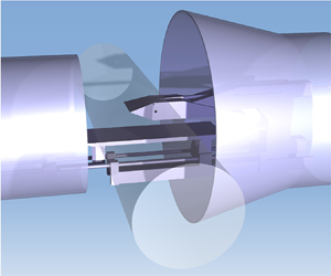
  $({\pm }3\,\%)$. As shown in figure 2(a), the test model, mounted downstream of the nozzle, contains a shock generator and a plate, and two 300 mm diameter glass windows are embedded in two sides of the test section walls for optical diagnostics. As shown in figure 2(b), the rotatable wedge can generate flow deflection angles from $0^\circ$ to $40^\circ$, and the plate can move horizontally to a distance of 200 mm. As shown in figure 2(c), the plate is 755 mm long and 160 mm wide, two Kulite XTEL-190 M transducers (K $_1$ and K $_2$) are mounted in the plate along the central line, and the distances to the leading edge of the plate are 400 mm (K $_1$) and 420 mm (K $_2$).

Figure 2. Schematic of the experimental set-up: (a) test model and optical diagnostics, (b) arrangement of the rotatable wedge and movable plate, and (c) locations of the Kulite transducers.
The time history of the total pressure  $p_0$ of the incoming flow is shown in figure 3(a). The results indicate that the wind tunnel started at $t_0$ (0 s), flow was established at $t_1$ (1.2 s), and the wind tunnel stopped at $t_4$ (6.9 s). An infrared detector (FLIR T630sc) was employed to capture the natural transition of boundary flow on the plate (without impinging shock), and the time history of the heat flux density $q$ at the location of K $_2$ is illustrated in figure 3(b). Here, the stable stage was during $t_1$ and $t_4$ depending on the running time of the wind tunnel. Figures 3(c) and 3(d) show the heat flux density map and distribution along the central line $l_0$ on the plate at $t=4.0$ s without shock impingement, respectively, demonstrating that the transition region was located between $x_1$ ( $\approx$201 mm) and $x_2$ ( $\approx$396 mm); thus, both K $_1$ (400 mm) and K $_2$ (420 mm) resided in the turbulent region.

Figure 3. Incoming flow properties and flow pattern on plate without shock impingement during the wind tunnel running process: (a) time history of the total pressure of the incoming flow, (b) time history of the heat flux density at location of K $_2$, (c) heat flux density map on the plate at $t=4.0$ s, and (d) distribution of the heat flux density along $l_0$ at $t=4.0$ s.
An NAC (NAC Image Technology) HotShot high-speed camera operated at a frame rate of 5 kHz with a 6 s sampling time and a resolution of  $600\times 438$ pixels was employed to take schlieren images. In each test, to capture a successive pressure distribution of the separation region, after the flow field with shock impingement was established, the plate moved from an upstream position where both K $_1$ and K $_2$ were ahead of the separation bubble ( $5.9 \times 10^6$ of the local Reynolds number at the separation point), as shown in figure 4(a), to a downstream position where K $_1$ and K $_2$ were behind the separation bubble ( $5.4\times 10^6$ of the local Reynolds number at the separation point), as shown in figure 4(b). Both K $_1$ and K $_2$ acquired data at 1 MHz with a 15 s sampling time covering the movement of the plate, which moved at a rate of $40\ \textrm {mm}\ \textrm {s}^{-1}$ driven by a high-precision stepper motor during $t_2$ (2.0 s) to $t_3$ (6.0 s). The plate movement employed a high-precision linear bearing motion pair to ensure stability and straightness. Therefore, both K $_1$ and K $_2$ can measure the local pressure along the shock impingement area at high spatiotemporal resolution (a time interval of $10^{-6}$ s and a space interval of $4\times 10^{-5}$ mm), as shown in figures 4(c) and 4(d). The time histories of K $_1$ and K $_2$ during the period of $t_2$ to $t_3$ could be converted to spatial distributions according to the plate movement speed. In addition, because the results of K $_1$ and K $_2$ were quite similar, the following analysis of the pressure distribution is mainly based on K $_2$.
$_2$.

Figure 4. Flow structures and pressure distributions: (a) schlieren image when K $_1$ and K $_2$ were ahead of the separation bubble, (b) schlieren image when K $_1$ and K $_2$ were after the separation bubble, (c) pressure distribution captured by K $_1$, and (d) pressure distribution captured by K $_2$.
$_2$.
To characterize the influence of the impinging shock strength on the pressure distribution of separation, the wedge in all the tests was set at different angles and kept stable during each test. Because the wall pressures of all the tests were analysed based on K $_2$, the local Reynolds numbers ahead of the separation point were the same ( ${\approx }5.9\times 10^6$), and the boundary-layer thickness was approximately 9 mm. Figure 5 illustrates flow interaction structures in the schlieren images, pressure distributions captured by K $_2$ and position-frequency maps calculated by power spectral density (PSD) at three typical angles of impinging shock. It can be observed in figure 5(a) that the separation bubble is very small and that the interaction point is almost immersed in the boundary layer when the flow deflection angle of the impinging shock is $\alpha =14.9^\circ$. Figure 5(b) shows the corresponding pressure distribution, where the black line is raw data and the red line is data filtered by 100 Hz. Although these data indicate a monotonic rise of Rise I, it is difficult to distinguish Rise I from Rise II in the separation region. Figure 5(c) demonstrates the pressure fluctuation energy map, where the dominant frequencies are mainly below 10 $^5$ Hz and reside in the shock impingement area. When the flow deflection angle increases to $\alpha =18.6^\circ$, the separation bubble grows larger, as shown in figure 5(d). Rise I and Rise II have a clear boundary, and Rise I is still monotonic, as shown in figure 5(e). The amplitudes of the pressure fluctuations in both the separation and impingement areas increase, and the energy at low frequencies (<5000 Hz) grows stronger, as shown in figure 5( f). For a relatively large flow deflection angle of $\alpha =24.5^\circ$, as shown in figure 5(g), the separation bubble is conspicuous, and Rise I exhibits a wide region ( $\approx$38 mm) with a non-monotonic change, as shown in figure 5(h). The energy of the pressure fluctuation shows further growth, and the frequency components in the separation area are below $8\times 10^4$ Hz, while in the impingement area, the frequency components reach $1.5\times 10^5$ Hz, as shown in figure 5(i). According to (2.9), the critical angle of Mach number 5 is $\alpha ^\ast \approx 20.8^\circ$. Based on the MEP results mentioned above, for both $\alpha =14.9^\circ$ and $18.6^\circ$ (figure 5a–f), the flow deflection angles are smaller than the critical angle, and the pressure rise is nearly linear with increasing flow deflection angle, while for $\alpha =24.5^\circ$ (figure 5g,i), which is larger than the critical angle, the pressure plateau shows a declining tendency after its peak value.

Figure 5. Flow structures, pressure distributions and position-frequency map induced by shock impingement at  $M_\infty =5$ and a Reynolds number of $1.4\times 10^7\ \textrm {m}^{-1}$: (a–c) $\alpha =14.9^\circ$, (d–f) $\alpha =18.6^\circ$ and (g–i) $\alpha =24.5^\circ$.
The pressure distributions induced by various flow deflection angles ranging from  $8.5^\circ$ to $30.5^\circ$ are summarized in figure 6(a), where all the pressure curves are filtered and aligned with separation points. It can be clearly observed that the Rise I curves almost coincide although they have different pressure plateau widths, indicating that all cases show the same initial separation portions. In contrast, the downstream portions are strongly affected by the impinging shock strength, which proves that the boundary layer dominates the upstream separation and that the main influencing factor of the downstream structure is impinging shock. Here $p_p$ and $p_e$ denote the plateau pressure and pressure at the end of Rise I, respectively, as shown in figure 5( f). The comparison between the experimental results and theoretical results is summarized in figure 6(b), where the uncertainties (error bars) of the experimental results are given by standard deviations. Figure 6(b) shows that the (2.6) curve characterizes the evolution law of $p_e$ with changing $\alpha$. This result shows the same tendency as the experimental results, while $p_p$ is closer to the other equations. The theoretical lines of (1.2) (see Schmucker Reference Schmucker1973) and (1.3) (see Chapman et al. Reference Chapman, Kuehn and Larson1958) are slightly larger than the line of (1.1) (see Zhukoski Reference Zhukoski1967), and (1.1) agrees very well with the experimental results of $p_p$ when $\alpha >\alpha ^\ast$ ( $20.8^\circ$). This means that the separation induced by a relatively strong impinging shock is similar to the separation induced by forward-facing steps. Additionally, figure 6(b) shows that the pressure plateau predicted by FIT is larger than that of the MEP. When $\alpha >\alpha ^\ast$, the peak value of the pressure plateau attempts to reach FIT, while the end value of the pressure plateau tries to match MEP. Thus, the final pressure rise of the separation region is non-monotonic, as shown in figure 6(a). This results in different pressure distributions demarcated by $\alpha =20.6^\circ$, which agrees well with the predicted $\alpha ^\ast \approx 20.8^\circ$. Therefore, a pressure plateau may not appear if the impinging shock is not sufficiently strong, and the pressure rise may be suppressed by the impinging shock; when a pressure plateau appears, it is mainly determined by the boundary layer.

Figure 6. Experimental results at various flow deflection angles of the impinging shock: (a) pressure distributions and (b) plateau pressures.
4. Conclusions
The current study investigates the pressure distribution characteristics in the separation region induced by shock impingement. A fitted equation based on the MEP is proposed to establish the relation between pressure rise and impinging shock strength. The pressure distributions induced by a series of shock impingements are measured at high spatiotemporal resolution in a flow of Mach number 5. The following conclusions are obtained.
The impinging shock strength plays an important role with respect to the pressure distribution of the separation region, and the relation curve of the proposed equation predicts how shock impingement affects the separation region, which is proven by current experiments. The influence of the impinging shock exerted on the pressure rise might not be monotonic for high Mach numbers ( $M_\infty \geqslant$ 5), and there is a critical flow deflection angle $\alpha ^\ast$ ( ${\approx }20.8^\circ$ for $M_\infty =5$). For the situation of $\alpha \leqslant \alpha ^\ast$, the pressure rise of separation grows nearly linearly with the impinging shock strength, and the pressure, which does not reach the pressure plateau predicted by FIT, might be suppressed by the impinging shock. For $\alpha >\alpha ^\ast$, the pressure rise might stop growing and shows a non-monotonic change, which may approach the pressure plateau predicted by FIT. Therefore, the flow structure of separation induced by shock impingement is codetermined by the boundary layer and impinging shock strength. The former shapes the upstream portion of separation, and the initial pressure rises induced by different impinging shock waves may coincide when upstream flow conditions are the same. The latter affects the downstream portion of separation, resulting in different end pressure rises with different widths. This law might be useful for understanding SWBLIs induced by shock impingement.
Funding
This work was supported by the National Natural Science Foundation of China (12002163; 12072157; 92252105), Natural Science Foundation of Jiangsu Province (BK20200408), China Postdoctoral Science Foundation (2022T150321), and Key Laboratory of Hypersonic Aerodynamic Force and Heat Technology, AVIC Aerodynamics Research Institute. This support is gratefully acknowledged.
Declaration of interests
The authors report no conflict of interest.


