


1. Introduction
Singularities occur in many branches of physics from the gravitational collapse of a black hole (Chandrasekhar Reference Chandrasekhar1992; Choptuik Reference Choptuik1993) to the pinch-off of a drop from a faucet (Brenner et al. Reference Brenner, Eggers, Joseph, Nagel and Shi1997; Eggers Reference Eggers1997; Eggers & Fontelos Reference Eggers and Fontelos2015). The reduced length and time scales near the singularity expose the important force balance governing the dynamics. The pinch-off of a drop from a nozzle was shown by Day, Hinch & Lister (Reference Day, Hinch and Lister1998) to have a self-similar conical shape with capillary–inertial scaling of the necking radius versus time,  $R \sim (\sigma t^{2}/\rho )^{1/3}$, where $\sigma$ is surface tension and $\rho$ the liquid density. In contrast the pinch-off of a bubble follows a purely inertial process with $R \sim (t_{c}-t)^{1/2}$ (Burton, Waldrep & Taborek Reference Burton, Waldrep and Taborek2005; Eggers et al. Reference Eggers, Fontelos, Leppinen and Snoeijer2007; Thoroddsen, Etoh & Takehara Reference Thoroddsen, Etoh and Takehara2007a). This modest difference in exponent values hides a profound difference in the dynamical nature of the pinch-off. For the purely inertial scaling, the surface tension becomes irrelevant near the final pinch-off and there is a strong dependence on the initial or boundary conditions. This memory of the boundaries has been best demonstrated for the pinch-off of a bubble from an elliptic nozzle (Schmidt et al. Reference Schmidt, Keim, Zhang and Nagel2009; Lai Reference Lai2012). Air cavities formed by the impact of circular plates with periodic edges produce kindred non-axisymmetric shapes, which can even split into multiple necks (Enriquez et al. Reference Enriquez, Peters, Gekle, Schmidt, Lohse and van der Meer2012).
For the collapse of impact craters, Thoroddsen et al. (Reference Thoroddsen, Takehara, Nguyen and Etoh2018) have recently shown that the finest singular jets emerge from a dimple collapse with close to inertial scaling.
Fine jets can emerge from a free surface in numerous configurations, such as: the oscillation of a free-falling drop pinched off from a nozzle (Thoroddsen, Etoh & Takehara Reference Thoroddsen, Etoh and Takehara2007b); from a bursting bubble at a pool surface (Duchemin et al. Reference Duchemin, Popinet, Josserand and Zaleski2002; Walls, Henaux & Bird Reference Walls, Henaux and Bird2015; Deike et al. Reference Deike, Ghabache, Liger-Belair, Das, Zaleski, Popinet and Séon2018; Lai, Eggers & Deike Reference Lai, Eggers and Deike2018); from shock-accelerated curved interfaces (Antkowiak et al. Reference Antkowiak, Bremond, Le Dizès and Villermaux2007; Thoroddsen et al. Reference Thoroddsen, Takehara, Etoh and Ohl2009; Tagawa et al. Reference Tagawa, Oudalov, Visser, Peters, van der Meer, Sun, Prosperetti and Lohse2012); following a drop impact on a superhydrophobic surface (Bartolo, Josserand & Bonn Reference Bartolo, Josserand and Bonn2006); during cylindrical collapse of sphere-impact craters (Gekle et al. Reference Gekle, Gordillo, van der Meer and Lohse2009) and from critical Faraday waves in vertically oscillated liquid layers (Longuet-Higgins Reference Longuet-Higgins1983; Zeff et al. Reference Zeff, Kleber, Fineberg and Lathrop2000; Das & Hopfinger Reference Das and Hopfinger2008).
Herein, we study jets forming by the collapse of hemispheric drop-impact craters. While numerous studies have looked at the crater collapse when the drop and pool are of the same liquid (Pumphrey & Elmore Reference Pumphrey and Elmore1990; Prosperetti & Oguz Reference Prosperetti and Oguz1993; Liow Reference Liow2001; Thoroddsen et al. Reference Thoroddsen, Takehara, Nguyen and Etoh2018), few have studied a drop impacting a pool of a different immiscible liquid. Earlier work has mostly focused on drop deformation (Fujimatsu et al. Reference Fujimatsu, Fujita, Hirota and Okada2003), fragmentation into smaller droplets (Lhuissier et al. Reference Lhuissier, Sun, Prosperetti and Lohse2013), a novel type of double entrainment (Jain et al. Reference Jain, Jalaal, Lohse and van der Meer2019) or breakup of oil spills by rain (Murphy et al. Reference Murphy, Li, d'Albignac, Morra and Katz2015). We will show that the landscape for singular jetting becomes much more complicated in the immiscible case.
2. Experimental set-up
The overall set-up is sketched in figure 1(c) and is similar to that used in previous studies on this topic by Thoroddsen et al. (Reference Thoroddsen, Takehara, Nguyen and Etoh2018). The drop pinches off from a flat stainless steel nozzle and falls onto a pool surface contained in a square glass container ( $5\ \textrm {cm} \times 5\ \textrm {cm} \times 5\ \textrm {cm}$). A syringe pump is used to feed the drop at a slow flow rate of $10\ \mathrm {\mu }\textrm {l}\,\textrm {min}^{-1}$. The drop diameters are less than 2 mm, so capillary waves are not reflected from the tank wall to influence the impact dynamics. Our well-controlled experiments exhibited extreme sensitivity to boundary conditions, as has been reported in Thoroddsen et al. (Reference Thoroddsen, Takehara, Nguyen and Etoh2018) and Michon, Josserand & Séon (Reference Michon, Josserand and Séon2017), who call the jetting ‘barely reproducible’.
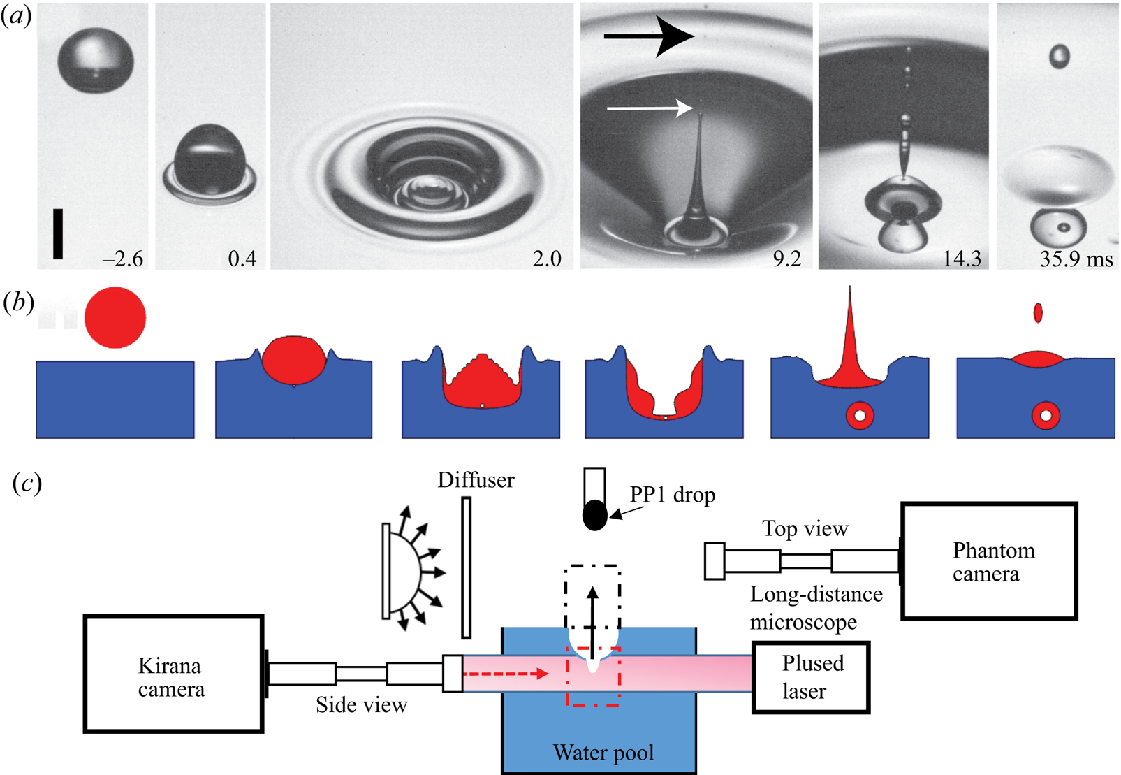
Figure 1.  $(a)$ Movie frames showing an angled top view of typical impact crater collapse and jetting, for $D=1.56\ \textrm {mm}$, $U=1.04\ \textrm {m}\,\textrm {s}^{-1}$, corresponding to $Re=3418$ and $We=242$. The scale bar is 1 mm long. See also supplementary movie 1 available at https://doi.org/10.1017/jfm.2020.694. $(b)$ Sketch of the drop impact, crater evolution, jetting and bubble entrapment. $(c)$ Experimental set-up, with two high-speed video cameras viewing from perpendicular directions, one for the dimple dynamics inside the pool and a second to view the jet droplets as they emerge out of the crater, as indicated by the arrow.
Herein, we use two immiscible liquids (table 1). The pool is deionized (DI) water (Milli-Q), while the drop consists of PP1 (Perfluorohexane, C $_6$F
$_6$F $_{14}$, from F2 Chemicals Ltd). The PP1 is 1.71 times heavier than water and has a very low surface tension $\sigma _d = 11.9\ \textrm {mN}\,\textrm {m}^{-1}$, as measured in house with a ring tensiometer (K100MK2/SF/C, Kruss GmbH, Hamburg). The interfacial tension between water and PP1 is $48\ \textrm {mN}\,\textrm {m}^{-1}$. The large difference in the refractive index makes the interface between the drop and pool clearly visible.
Table 1. Liquid properties of the PP1 drop and water pool.
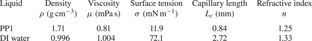
We use a range of PP1 drop sizes  $D = 0.60$, 0.72, 0.85, 0.95, 1.2, 1.5 and 2.0 mm. For reference, the capillary length for PP1 is $\sqrt {\sigma /(\rho g)} = 0.84\ \textrm {mm}$. By varying the drop release height we produce impact velocities $U$ between 0.1 and $3.9~\textrm {m}\,\textrm {s}^{-1}$. The corresponding range of Reynolds, Weber and Froude numbers, based on drop liquid properties are
 \begin{gather} Re = \frac{\rho_d DU}{\mu_d} = 374\text{--}10\,200, \end{gather}
 \begin{gather} We = \frac{\rho_d DU^{2}}{\sigma_d} = 10\text{--}2000, \end{gather}
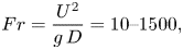 \begin{gather} Fr = \frac{U^{2}}{g\,D} = 10\text{--}1500, \end{gather}
where  $g$ is gravity, $\rho _d$ and $\mu _d$ drop density and dynamic viscosity.
Two high-speed cameras simultaneously observe the crater collapse and jetting. The top camera (Phantom V2511) focuses on the jet rising above the liquid pool surface, while the other one studies the crater collapse below the surface. The bottom Kirana camera can reach 5 Mfps at  ${\sim } 1\ \mathrm {\mu }\textrm {m}\,\textrm {px}^{-1}$ resolution when using a long-distance microscope (Leica Z16 APO). Back lighting is produced by 350 W Sumita metal-halide lamp shone onto a diffuser, or by pulsed laser diodes (SI-LUX640, Specialized Imaging) at the highest frame rates.
3. Results
The impact forms a hemispheric crater into the pool surface, with the drop liquid stretched out into a thin continuous layer coating its surface. The subsequent rebound can form a bottom dimple whose collapse pinches off a bubble, or can produce singular jets (Rein Reference Rein1996; Liow Reference Liow2001; Michon et al. Reference Michon, Josserand and Séon2017; Thoroddsen et al. Reference Thoroddsen, Takehara, Nguyen and Etoh2018). This is shown by the sequence of movie frames and sketches in figure 1(a,b) and the sequence in figure 2, showing the jet emergence and its break-up above the pool surface. The free surface of the bottom dimple therefore remains between the air and the PP1 drop liquid and has low surface tension. Figure 3 shows the parameter regime where a dimple forms at the bottom of the crater during its collapse. The boundary of this regime is marked by solid black lines. This occurs at a much larger  $We$ (based on drop properties), than for the classical regime (marked by dashed blue lines) where the bottom dimple entraps a bubble for identical liquids in both drop and pool (Pumphrey & Elmore Reference Pumphrey and Elmore1990; Prosperetti & Oguz Reference Prosperetti and Oguz1993). The phase diagram in figure 3(b) classifies the impact outcomes within the dimple-formation region, which is bounded between the two solid black curves. There is no air-dimple pinch-off above the upper bound and below the lower bound. Note that, because the surface tension and density of the drop liquid are constant in the experiments, by increasing the impact velocity, for a fixed drop diameter, one traces out a straight line from the origin, in the We–Fr diagram. The intermediate region, between the curves is classified into different dimple shapes. Not only do we see pinch-off of a single bubble, but other more complex shapes are produced, owing to capillary waves travelling down the dimple. There are prominent bamboo-shaped dimples which appear in a subregion marked by the cyan dashed lines. Adjacent to this region we see the formation of telescopic dimples, marked by black stars, where no bubble is pinched off but the narrowest and fastest jets are observed. Furthermore, we find singular jets occurring at numerous locations within the dimple regime. This is in sharp contrast with crater collapse for cases when the drop and pool are of the same liquid (Rein Reference Rein1996; Thoroddsen et al. Reference Thoroddsen, Takehara, Nguyen and Etoh2018), where jets form only at the boundaries of the dimple regime. For example, in figure 3(c) we show an enlargement of the region within the red dashed rectangle in figure 3(b), where the large symbols show three different impact conditions with singular jets at different $We$, as shown later in figure 9.
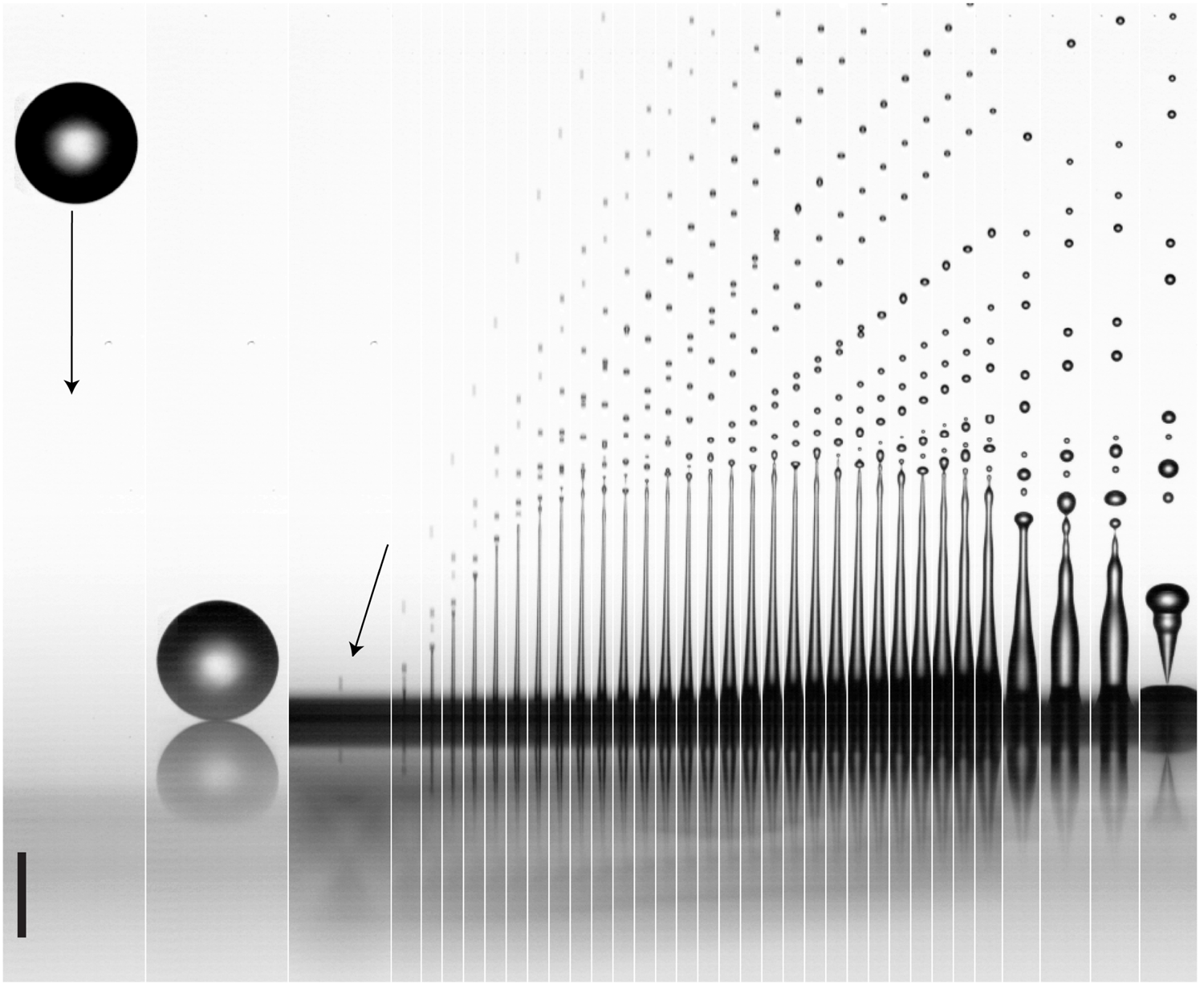
Figure 2. Overall shape and break-up of the fine jet emerging out of the impact crater for a PP1 droplet of  $D = 0.71\ \textrm {mm}$, impacting on the water pool at velocity $U = 1.18\ \textrm {m}\,\textrm {s}^{-1}$, giving $Re = 1779$, $Fr = 201$, $We = 143$. This corresponds to the first singular jet for this drop size, emerging at a jet velocity of $v_{jet}= 7.59\ \textrm {m}\,\textrm {s}^{-1}$. The total number of shed droplets is here 21. The movie is taken at 70 kfps and the second panel shows the drop hitting the free surface. The first tip droplet is $21\ \mathrm {\mu }\textrm {m}$ wide and emerges in the third panel (arrow) at 2.2 ms after the impact. Subsequent frames are separated by $57\ \mathrm {\mu }\textrm {s}$, with the last four frames at $t= 4.14$, 4.48, 4.57 and 4.66 ms after impact. The scale bar is $500\ \mathrm {\mu }\textrm {m}$ long. See also supplementary movie 2.
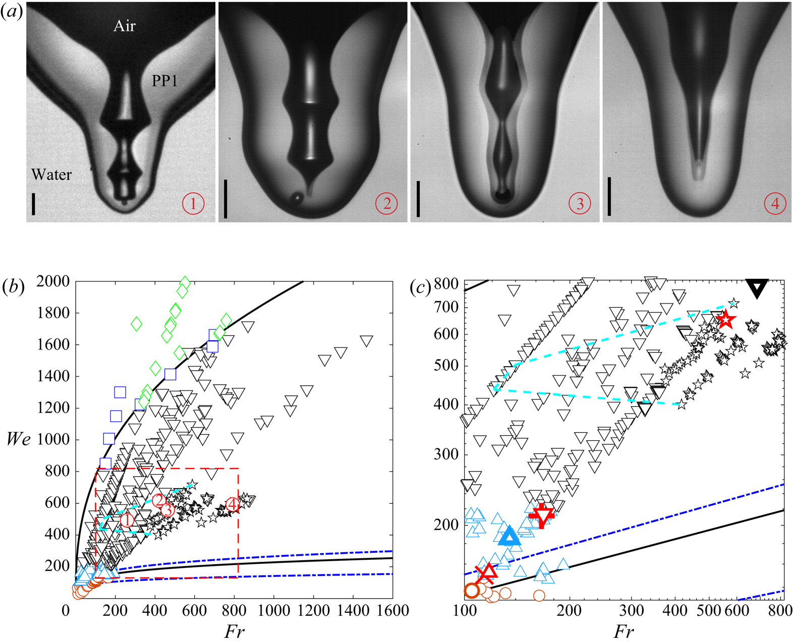
Figure 3.  $(a)$ Typical dimple shapes for different impact conditions in the multi-dimple regime corresponding to the circled red numbers in $(b)$. Three bamboo-shaped dimples:
 ![]() $D=1.16\ \textrm {mm}$, $U=1.7\ \textrm {m}\,\textrm {s}^{-1}$, $Fr=259$, $We= 493$;
 ![]() $D=1.02\ \textrm {mm}$, $U=2.1\ \textrm {m}\,\textrm {s}^{-1}$, $Fr=421$, $We= 617$;
 ![]() $D=0.93\ \textrm {mm}$, $U=2.05\ \textrm {m}\,\textrm {s}^{-1}$, $Fr=463$, $We= 560$ and a singular telescopic dimple:
 ![]() $D=0.73\ \textrm {mm}$, $U=2.38\ \textrm {m}\,\textrm {s}^{-1}$, $Fr=792$, $We= 593$. The scale bars are $100\ \mathrm {\mu }\textrm {m}$ long. $(b)$ Characterization of the dimples and jets in $Fr{-}We$ space for drop impacts of immiscible liquids. The two dashed curves are the bounds of the regular bubble-entrapment regime at the bottom of the rebounding crater, measured by Pumphrey & Elmore (Reference Pumphrey and Elmore1990) and fitted by Oguz & Prosperetti (Reference Oguz and Prosperetti1990). The two solid curves mark the bubble-entrapment region based on our study. This region also includes isolated points of singular jetting, like the one shown in case 4 in panel $(a)$. The symbols correspond to different dimple shapes: ( $\bigcirc$, magenta) no pinch-off shallow dimple; ( $\triangle$, cyan) dimple pinch-off with bubble going out with the jet; ( $\triangledown$, black) bubble pinches off and is entrapped inside PP1 drop liquid; (
![]() , black) telescopic dimple without pinch-off; (
, black) telescopic dimple without pinch-off; ( $\Box$, blue) drop liquid column breaks up without an air-dimple pinch-off, as shown in figure 4(a); ( $\Diamond$, green) water entrapped inside PP1 drop liquid, without bubble pinch-off. $(c)$ Enlarged region corresponding to the rectangular box marked by the red dashed lines in $(b)$. The dashed cyan lines (- -, cyan) mark the region where bamboo-like multi-dimples appear (see details in $(a)$ and figure 5a). The larger symbols with thick edges correspond to conditions similar to those shown in figure 6; ( $\bigcirc$, magenta, $\triangle$, cyan and $\triangledown$, black) indicate the same dimple shapes as in $(b)$; ( $\times$, red) first critical pinch-off (first singular jet) at the boundary between no and one bubble pinch-off; ( $\triangle$, red) tiny bubble pinched off near first critical pinch off; ( $+$, red) secondary critical pinch-off between bubble going out with the jet and bubble entrapped in PP1 drop; ( $\triangledown$, red) tiny bubble pinched off near secondary critical pinch-off; (
![]() , red) singular telescopic dimple.
, red) singular telescopic dimple.
Keep in mind that the region close to the lower bound of the dimple-formation regime in figure 3(b), corresponds to the smallest drops,  $D \simeq 0.7\text {--}0.9\ \textrm {mm}$, which are close to the size of the capillary length 0.82 mm. The oscillations of the free-falling drop, away from spherical shape, will therefore be minimal and unlikely to affect the crater dynamics significantly, as can occur for larger drops. We refer to Thoraval, Li & Thoroddsen (Reference Thoraval, Li and Thoroddsen2016), where the shape at first contact determines whether a large bubble is entrapped or not.
For impacts above this bubble-entrapment regime, we see the bottom of the drop form into a cylindrical liquid dimple which pinches off, as shown in figure 4(a); see also Lhuissier et al. (Reference Lhuissier, Sun, Prosperetti and Lohse2013). Here the bottom of the air cavity retracts upwards without bubble pinch-off. However, the PP1 cylinder pinches off a satellite droplet inside the water pool through Rayleigh–Plateau instability. The reversed air cavity shown in the third frame of figure 4(a) is reminiscent of the secondary-bubble-entrapment dimple of Liow & Cole (Reference Liow and Cole2007), even though there is no bubble pinch-off in our case.
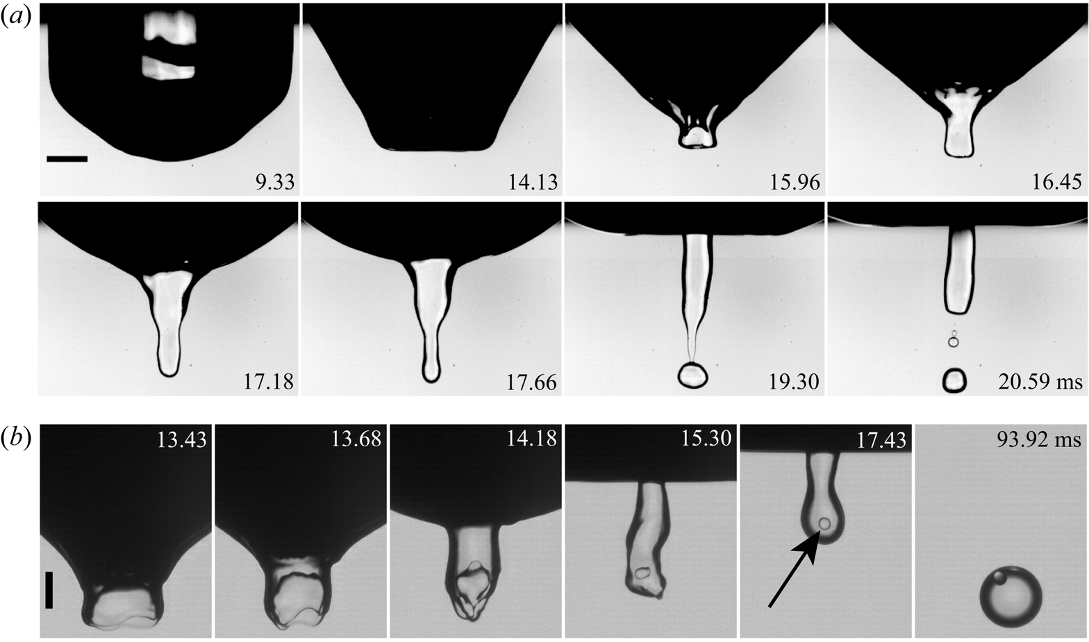
Figure 4. Dimple shapes above the upper boundary of the regime of air-dimple formation, above solid line in figure 3(b).  $(a)$ Overall view of the pinch-off of a dimple of PP1 drop liquid, without air-bubble pinch-off, for $U = 2.29\ \textrm {m}\,\textrm {s}^{-1}$ and $D = 1.63\ \textrm {mm}$, giving $Re= 7862$, $Fr= 328$, $We = 1224$. The drop liquid forms a column which pinches off due to Rayleigh–Plateau instability. There is no air-cavity pinch-off indicated by ( $\Box$, blue) in figure 3(b). The scale bar is 1 mm. $(b)$ The evolution of water–PP1–water compound drop formation, which corresponds to ( $\Diamond$, green) in figure 3(b). $U = 3.57\ \textrm {m}\,\textrm {s}^{-1}$ and $D = 1.20\ \textrm {mm}$, giving $Re= 8902$, $Fr= 1099$, $We = 2162$. The black arrow indicates the entrapped water droplet in PP1. In the last frame, the less dense water droplet has risen to the top of the PP1 droplet. The scale bar is $500\ \mathrm {\mu }\textrm {m}$. See also supplementary movies 3 and 4.
In figure 4(b), the bottom surface of the PP1 column shows a reverse-curvature PP1–water interface. The dynamics engulfs some of the water to form a water–PP1 compound droplet, which is indicated by the black arrow in figure 4(b). A related process is found in the study of Terwagne et al. (Reference Terwagne, Mack, Dorbolo, Gilet, Raty and Vandewalle2009), where they bounce a water drop coated with a thin silicon oil layer on a high-viscosity pool surface. The deformation of the drop entraps some of the surface oil film into the water drop, thereby forming a double emulsion. See also the engulfment of a pool droplet inside a contracting air disc, which is entrapped under an impacting drop (Jian et al. Reference Jian, Channa, Kherbeche, Chizari, Thoroddsen and Thoraval2020).
3.1. Capillary waves on dimple
Figure 3(a) shows a prominent new feature of the dimples, i.e. capillary waves travelling down towards their tips, forming the bamboo-like shapes. Some of these shapes evolve into two or even three pinch-offs, like the double pinch-off shown in figure 5(a). Figure 6 shows the progression of wave shapes along a cut through parameter space, where we keep the drop size fixed at  $D=0.94\pm 0.02\ \textrm {mm}$, while increasing the impact velocity, to span a range of $We$ from 162 to 1510. With increasing $We$, the number of visible wave crests grows from one to three (middle panels) and then the dimple column becomes smooth again (last panels). The second row shows the shapes near the maximum depth, which includes pinch-off shapes and a singular telescopic dimple ( $We=653$), where no pinch-off occurs, but the fastest jets are ejected out of the crater. This intriguing telescopic shape occurs in a very limited region, within the more common multi-pinch-offs bamboo shapes shown in three of the panels in figure 3(a) and in figure 5(a).
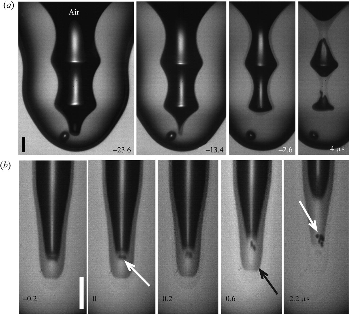
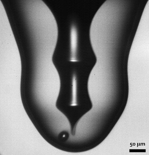
Figure 5.  $(a)$ Multi-pinch-off bamboo-like dimple shape, corresponding to
 ![]() in figure 3(a). Times are shown relative to the first pinch-off.
in figure 3(a). Times are shown relative to the first pinch-off.  $(b)$ Micro-bubble shedding from the cusp at the base of the singular jet, for $D=0.82\ \textrm {mm}$, $U=2.21\ \textrm {m}\,\textrm {s}^{-1}$, $Re=3826$, $We= 609$, $Fr=569$. The white arrows point at the shed micro-bubbles. The image sensor has strong ghosting from every tenth frame (black arrow). The scale bars are $50\ \mathrm {\mu }\textrm {m}$ long. See also supplementary movies 5 and 6.
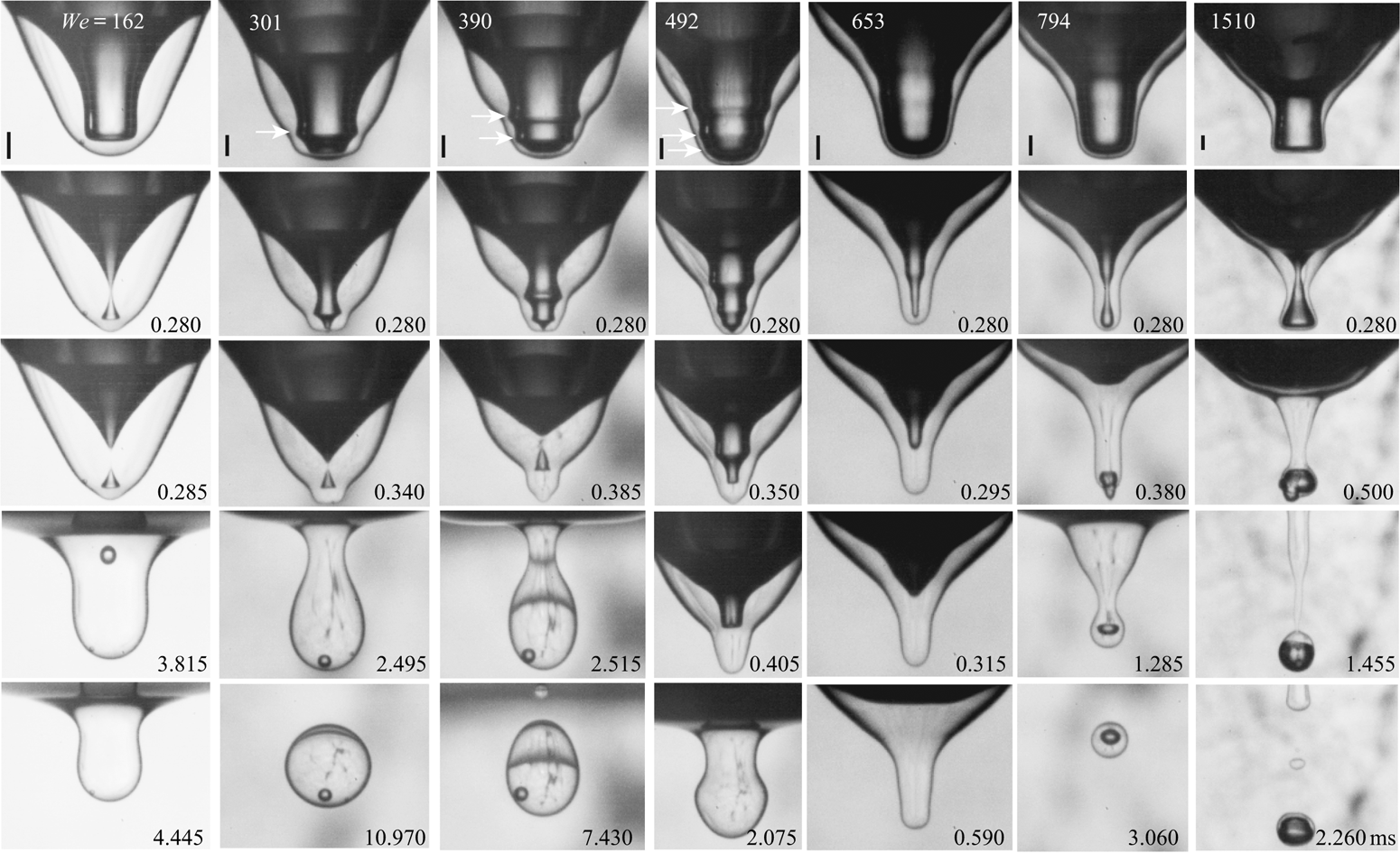
Figure 6. Capillary wave shapes on the dimple for a range of  $We$, for similar $D=0.935\pm 0.025\ \textrm {mm}$ and various impact velocities increasing from left to right: $U= 1.09$, 1.48, 1.72, 1.91, 2.23, 2.47 and $3.37\ \textrm {m}\,\textrm {s}^{-1}$. The arrows point out capillary wave troughs. The scale bars are 200 $\mathrm {\mu }\textrm {m}$ long. See also supplementary movies 7–13.
Figure 7 traces the trajectory of the wave troughs along the air–PP1 interface, for four of the cases in figure 6. We plot the vertical coordinate of the isolated waves versus time, until the maximum depth of the crater and radial collapse. The corresponding movies are listed in figure 6. During the early penetration of the drop into the pool, a prominent trough forms at its outer edge. This prominent wave trough travels down with the crater, producing other troughs ahead of itself. For  $We=301$ (figure 7a) it emits one wave and for $We=390$ (figure 7b) it forms two troughs, which reach the bottom before the primary wave. On the other hand, for somewhat larger $We$ these primary waves reach the bottom before the crater reaches maximum depth. A second round of wave troughs are now generated further up the crater wall, which again spawn new waves ahead of them, four in figure 7(c) and three in figure 7(d). The growth and shape of the crater makes it difficult to calculate the phase velocity of the troughs. Here, we only show that the vertical speed is in the correct range for capillary waves. In figure 7(b) we have fitted the three curves, finding downwards speeds of 0.31, 0.32 and $0.37\ \textrm {m}\,\textrm {s}^{-1}$. Shorter capillary waves travel faster $u_c = \sqrt {2{\rm \pi} \sigma /(\rho \lambda )}$, where $\lambda$ is the wavelength. Using the distance between crests in the inset of figure 7(b), we find wavelengths of 0.28, 0.19 and 0.18 mm, predicting quite similar velocities of 0.40, 0.49 and $0.50\ \textrm {m}\,\textrm {s}^{-1}$. The group velocity for capillary waves is $1.5\times u_c$, supporting the observation of shorter waves emerging ahead of the most prominent wave. Similar wave dynamics is generated by coalescing bubbles, where converging waves lead to partial coalescence (Zhang et al. Reference Zhang, Thoraval, Thoroddsen and Taborek2015).
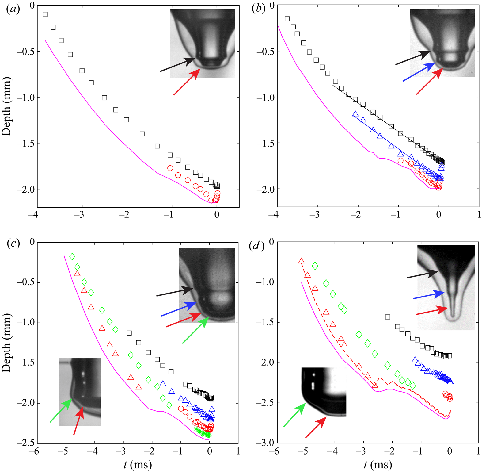
Figure 7. Trajectories of the wave troughs along the crater free surface for four cases from figure 6:  $(a)$
$(a)$ $We=301$; $(b)$
$(b)$ $We=390$; $(c)$
$(c)$ $We=492$; $(d)$
$(d)$ $We=653$. The magenta continuous curves mark the bottom penetration of the PP1 droplet at the centreline. The dashed red curve in $(d)$ marks the bottom of the air crater. The coloured arrows point out the troughs tracked by the corresponding coloured symbols. The original red and green tracks in (c,d) reach the bottom of the crater, while other waves are generated further up. The slopes of the lines in $(b)$ are $-0.31$, $-0.32$ and $-0.37\ \textrm {m}\,\textrm {s}^{-1}$ starting from the top curve.
Figure 8 shows two realizations where the internal jetting is visible inside the air cylinder. From these realizations it becomes clear that the classical picture of singular jets only appearing at the boundaries of the regular bubble-entrapment regime no longer applies and the phase of these capillary waves can induce singular jets at more  $We$ values. This is shown for $D=0.92\ \textrm {mm}$ in figure 9, with the corresponding jet speeds indicated by the arrow lengths. Here there are three separate $We$ values where no bubble is pinched off and a fast jet is produced (columns 2, 5 and 7). See figure 2 for the shape and break-up of these jets as they emerge from the crater (Yarin Reference Yarin1993; Michon et al. Reference Michon, Josserand and Séon2017; Lai et al. Reference Lai, Eggers and Deike2018). The fastest and thinnest jet is observed for the telescopic-dimple case ( $We=653$), which corresponds to the narrowest angular span of the air cylinder, where the maximum flow volume can be focused into the base of the jet. This narrow shape looks reminiscent of the capillary-driven retraction of a conical drop, studied by Brasz, Berny & Bird (Reference Brasz, Berny and Bird2018b).
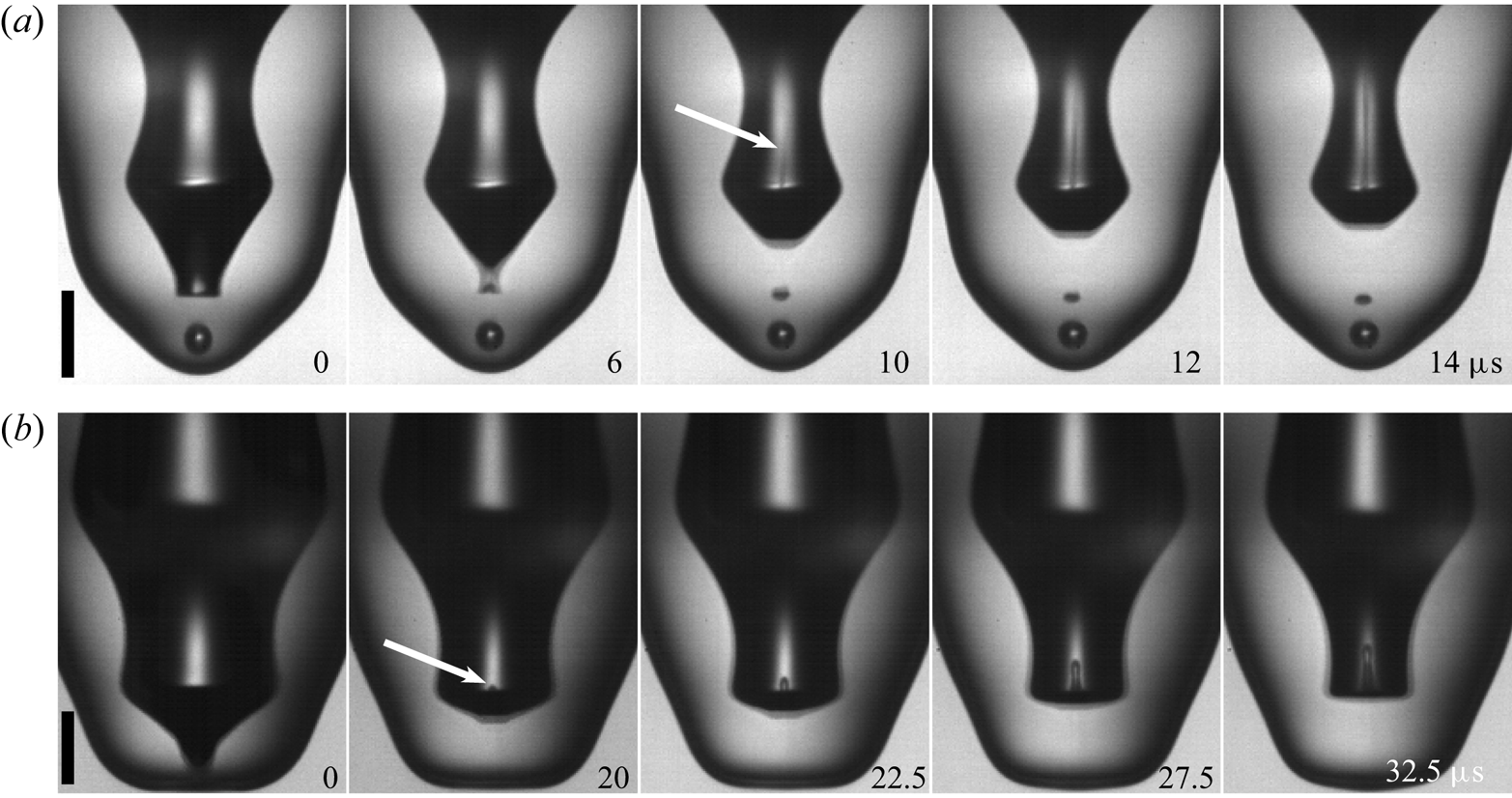
Figure 8. Early-time jet visible inside the air dimple. (a,b) Present the different singular jets in the cavity visualized by our imaging method. The white arrows indicate jettings inside the cavity. The scale bars are  $100\ \mathrm {\mu }\textrm {m}$ long. See also supplementary movies 14 and 15.
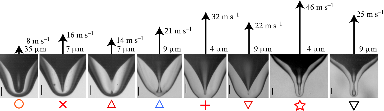
Figure 9. Overview of dimple shape and jet velocity versus  $We$, for drop size 0.92 mm. The arrow lengths indicate the jet velocities. The Weber number grows from left to right ( $We=137, 139, 153, 186, 211, 213, 653, 794$). The scale bars are $200\ \mathrm {\mu }\textrm {m}$. See also supplementary movies 7, 11 and 12.
3.2. Cross-over
The above dimple shapes show that not only can the boundary conditions break the axisymmetry of the collapse of a pinching air cylinder (Burton et al. Reference Burton, Waldrep and Taborek2005; Keim et al. Reference Keim, Møller, Zhang and Nagel2006; Enriquez et al. Reference Enriquez, Peters, Gekle, Schmidt, Lohse and van der Meer2012; Lai Reference Lai2012), but they can also imprint a large variety of axial shapes on the free surface of the dimple, thereby modifying its singular collapse.
What is the role of capillary waves in setting up the dimple for the inertial focusing? For the singular jets the dimple dynamics has until recently been formulated in the self-similar capillary–inertial formalism (Zeff et al. Reference Zeff, Kleber, Fineberg and Lathrop2000; Duchemin et al. Reference Duchemin, Popinet, Josserand and Zaleski2002; Deike et al. Reference Deike, Ghabache, Liger-Belair, Das, Zaleski, Popinet and Séon2018), while the final cylindrical collapse has most recently been shown to follow pure inertial focusing (Thoroddsen et al. Reference Thoroddsen, Takehara, Nguyen and Etoh2018; Gordillo & Rodríguez-Rodríguez Reference Gordillo and Rodríguez-Rodríguez2019). One can therefore expect a dynamical transition in the vicinity of the final jet formation. In figure 10(a) we track the radius of the pinch-off neck for a pinch-off case of the bamboo-shaped dimple, shown in the inset. There is here a clear cross-over in the nature of the dynamics from capillary–inertial  $R\sim t^{2/3}$ to purely inertial with $R\sim t^{0.55}$ at $t_c \simeq 65\ \mathrm {\mu }\textrm {s}$ before pinch-off, as marked by the arrow. Figure 10(b) shows that the cross-over time scales with the impact time $t_c \simeq 0.235 R_d/U$ for the cases where a small bubble is pinched off. On the other hand, for the fastest singular jetting the cross-over time occurs much earlier, irrespective of $We$. The vertical arrows indicate a lower bound for $t_c$, as the data have reached the end of the 180 frame video clip without deviating from the $\simeq 0.55$ power-law exponent. This difference is explicitly shown in the log–log plots in figure 10(c,d) where the singular collapse in $(d)$ follows the inertial power law for at least $500\ \mathrm {\mu }\textrm {s}$. We note that the measured exponent ${\simeq }0.55$, being significantly larger than the inertial power law of 0.5, is consistent with previous measurements of bubble pinch-off (Bergmann et al. Reference Bergmann, van der Meer, Stijnman, Sandtke, Prosperetti and Lohse2006; Thoroddsen et al. Reference Thoroddsen, Etoh and Takehara2007a), which is explained by the slow asymptotic observed in the corresponding theory (Eggers et al. Reference Eggers, Fontelos, Leppinen and Snoeijer2007; Gordillo & Fontelos Reference Gordillo and Fontelos2007).
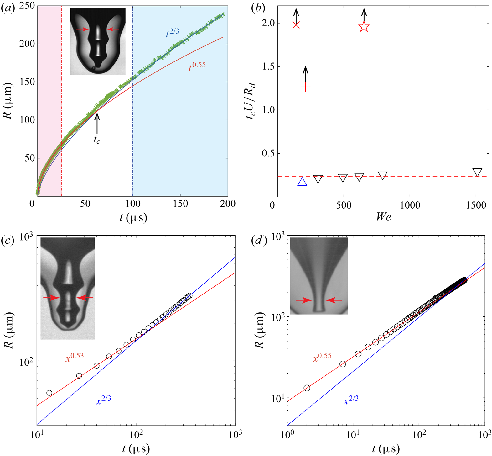
Figure 10.  $(a)$ Scaling of the dimple radius vs time before pinch-off, for $U= 2.05\ \textrm {m}\,\textrm {s}^{-1}$, $D =1.02\ \textrm {mm}$ and $Re= 4418$, $Fr= 421$, $We = 617$. There is a transition of power-law exponents from 2/3 to 0.55 closest to the pinch-off. The background shading marks the validity of each, with the arrow indicating the approximate cross-over time $t_c$. The data are taken from two movie clips spanning time scales from 100 ns to $200\ \mathrm {\mu }\textrm {s}$ before pinch-off. The corresponding log–log-plots are included in the supplementary material. $(b)$ The cross-over time $t_c$ normalized by the impact time $D/U$ vs $We$, for dimple pinch-off ( $\triangle$, cyan and $\triangledown$, black) and singular jets ( $\times$, red, $+$, red and
 ![]() , red). The vertical arrows indicate that these are lower bounds for
, red). The vertical arrows indicate that these are lower bounds for  $t_c$, due to finite length of the movie clips. (c,d) Show the pinch-off under different conditions. $(c)$
$(c)$ $U= 1.72\ \textrm {m}\,\textrm {s}^{-1}$, $D =1.2\ \textrm {mm}$ and $Re= 4215$, $Fr= 259$, $We = 493$. $(d)$ Singular jetting without bubble pinch-off, for $U= 1.21\ \textrm {m}\,\textrm {s}^{-1}$, $D= 0.99\ \textrm {mm}$, $Re= 2531$, $Fr= 152$, $We= 209$. The horizontal red arrows indicate the location where the minimum dimple radius is tracked.
This cross-over from capillary–inertial scaling can also be revealed by the local prefactor in the capillary–inertial power law, i.e.  $C = R / (\sigma t^{2}/\rho )^{1/3}$ (Burton, Rutledge & Taborek Reference Burton, Rutledge and Taborek2004, Reference Burton, Rutledge and Taborek2007; Deblais et al. Reference Deblais, Herrada, Hauner, Velikov, Van Roon, Kellay, Eggers and Bonn2018). Figure 11 shows that $C$ is approximately constant during the early capillary-driven stage, but then increases steadily on approaching the final pinch-off. The value of $C$ is linearly proportional to the radial velocity $\textrm {d}R/\textrm {d}t = (2C/3) (\sigma /\rho )^{1/3} t^{-1/3}$ and the rise in $C$ indicates the accelerated collapse due to the inertial focusing, exceeding the speed of the capillary-driven motions. The value of $C=3.7$ is much larger than for a drop pinching off from a nozzle, which has recently been investigated by Deblais et al. (Reference Deblais, Herrada, Hauner, Velikov, Van Roon, Kellay, Eggers and Bonn2018), where $C \le 0.717$. If we use the density of the water pool and the interface tension between drop and pool, $C_{water}$ reduces to 1.95. This indicates that the inertia of the pool is more important, during the early motions, than that of the thin drop layer. We also find that the value of $C$ is fairly constant over the range of $We$, as shown in figure 11(d). Larger $We$ will increase the crater size and thereby reduce the thickness of the drop liquid surrounding the dimple, as is clearly seen in figures 6 and 9.

Figure 11. The instantaneous prefactor  $C$ of the capillary–inertial scaling, as a function of time before the pinch-off collapse, for different Weber numbers: $(a)$
$(a)$ $We = 264$, $(b)$
$(b)$ $We = 493$, $(c)$
$(c)$ $We = 1510$. Values are calculated with PP1 properties. The approach to the singularity goes from right to left ( $t \rightarrow 0$). The initial dynamics follows the capillary–inertial power law with a constant prefactor (red circles), while closer to the singularity the velocity speeds up (blue circles), indicating inertial acceleration and power-law scaling transition from 2/3 to 0.55. $(d)$ Prefactors calculated with water density and water–PP1 interfacial tension, which is indicated by the subscript $C_{water}=0.53\, C$.
The prefactor during the final inertial collapse arises from the balance of two inertial terms, acceleration and convection (Eggers et al. Reference Eggers, Fontelos, Leppinen and Snoeijer2007). In the final stage the prefactor should therefore not depend on the surface tension or the hydrostatic pressure. We are therefore led to the simple scaling of
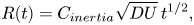 \begin{equation} R(t) = C_{inertia} \sqrt{DU}\, t^{1/2}, \end{equation}
which gives a fairly constant value of  $C_{inertia} \simeq 0.30 \pm 0.04$, over the range of $We$ numbers tested, as shown in figure 12. This value is consistent with data from Thoroddsen et al. (Reference Thoroddsen, Takehara, Nguyen and Etoh2018), included in the figure. Keep in mind that these data are for larger drops and different liquid properties. However, the viscosity in that study is larger and more systematic testing is needed to verify this relation, over a wider range of properties. Relating this formula to the bursting of a static bubble, one can use the capillary–inertial velocity, based on the bubble radius $R_b$, $u_{\sigma } = \sqrt {\sigma /(\rho \, R_b)}$, to get $R(t) \sim (\sigma R_b/\rho )^{1/4} t^{1/2}$, in accordance with Burton et al. (Reference Burton, Waldrep and Taborek2005).
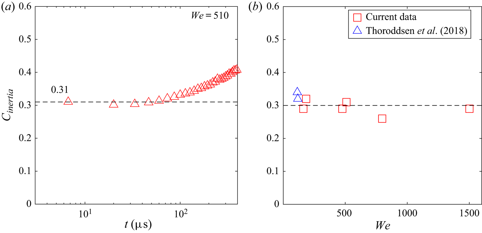
Figure 12. Scaling prefactor during the final inertial collapse, using (3.1).  $(a)$ The asymptotic value of the prefactor $C_{inertia}$ vs time before pinch-off, for $We=510$. $(b)$ The coefficient over a range of $We$, including data from Thoroddsen et al. (Reference Thoroddsen, Takehara, Nguyen and Etoh2018) (their figure 5), where the drop size, density and surface tension are quite different from the current study.
4. Discussion and conclusions
Herein, we report a plethora of new dimple shapes, which occur following a drop impact on an immiscible pool. This includes multiple pinch-off bamboo shapes from capillary waves, which mould the axial shape of the dimple before its final purely inertial collapse. This destroys any hope of finding a universal self-similar dimple shape. We have also identified many discrete  $We$-values where singular jetting is observed.
Questions remain: what determines the minimum diameter of the singular dimple and thereby its maximum jetting velocity? The smallest singular dimple width is here  $\simeq 12\ \mathrm {\mu }\textrm {m}$ which is similar to the $15\ \mathrm {\mu }\textrm {m}$ observed by Thoroddsen et al. (Reference Thoroddsen, Takehara, Nguyen and Etoh2018), who used a liquid which is an order of magnitude more viscous. This suggests that a viscous cutoff is not at play for the much lower viscosity of our PP1 drop (Castrejón-Pita et al. Reference Castrejón-Pita, Castrejón-Pita, Thete, Sambath, Hutchings, Hinch, Lister and Basaran2015; Brasz et al. Reference Brasz, Bartlett, Walls, Flynn, Yu and Bird2018a). We can speculate that cavitation or vortex-shedding instability (Thoraval et al. Reference Thoraval, Takehara, Etoh, Popinet, Ray, Josserand, Zaleski and Thoroddsen2012) in the cusp at the base of the jet prevents smaller jet sizes, as we see by the micro-bubbles shed at the base of the jet in figure 5(b). The expansion of the micro-bubble volume in the last panel indicates the large localized pressure driving up the singular jet (Tran et al. Reference Tran, Lee, Lee, Woo, Han, Kim and Hwang2016; Thoroddsen et al. Reference Thoroddsen, Takehara, Nguyen and Etoh2018; Gordillo & Rodríguez-Rodríguez Reference Gordillo and Rodríguez-Rodríguez2019).
We conclude that our singular jets differ from bubble-bursting jets, in fundamental ways. First, the dimple shapes are not self-similar during the final collapse (Duchemin et al. Reference Duchemin, Popinet, Josserand and Zaleski2002; Lai et al. Reference Lai, Eggers and Deike2018). Secondly, figures 6 and 9 show clearly that the Ohnesorge number, which is approximately constant,  $Oh=\mu _d/\sqrt {\rho _d R_c \sigma _d}\simeq 0.0054$, based on the maximum crater radius $R_c=1.1\ \textrm {mm}$, is not sufficient to describe the varied dynamics, as is suggested for bursting-bubble jetting (Gañán-Calvo Reference Gañán-Calvo2017, Reference Gañán-Calvo2018; Gordillo & Rodríguez-Rodríguez Reference Gordillo and Rodríguez-Rodríguez2019). It is a clear indication of the extreme focusing of energy that the maximum jetting velocity $v_j = 46\ \textrm {m}\,\textrm {s}^{-1}$ is $\sim 580 \pm 30$ times the capillary velocity $v_{\sigma }=\sqrt {\sigma _d/(\rho _d R_{c})}$. This is an order of magnitude faster than predicted for the bursting bubbles (Deike et al. Reference Deike, Ghabache, Liger-Belair, Das, Zaleski, Popinet and Séon2018; Gañán-Calvo Reference Gañán-Calvo2018; Gordillo & Rodríguez-Rodríguez Reference Gordillo and Rodríguez-Rodríguez2019). The jet diameters of $4\ \mathrm {\mu }\textrm {m}$ are also two orders of magnitude thinner than those predicted by the bursting-bubble theory (Gañán-Calvo Reference Gañán-Calvo2018), see also the Comment of Gordillo & Rodríguez-Rodríguez (Reference Gordillo and Rodríguez-Rodríguez2018), who question the underlying scaling of this theory. One clear difference from bursting bubbles is the residual velocity field, which exists at the start of crater collapse. Another is the generation of capillary waves at the edge of the impacting drop.
The cross-over from capillary-driven motions to inertial focusing is not unique to immiscible impacts. The inertial focusing in Thoroddsen et al. (Reference Thoroddsen, Takehara, Nguyen and Etoh2018) also appears to be preceded by a capillary–inertial stage, but is not mentioned in that work. We include one similar example in the supplementary material.
Finally, we point out that while the final inertial focusing occurs on tens of  $\mathrm {\mu }\textrm {m}$ length scales, the larger-scale liquid inertia is here a function of time, owing to the local thickness of the drop liquid around the dimple, which also becomes thinner with increasing $We$. This effect can be investigated by changing the relative density of the two liquids, in future experiments.
Acknowledgements
This study was supported by King Abdullah University of Science and Technology (KAUST) under grant URF/1/3727-01-01. We acknowledge useful discussions with J. Eggers, C. Y. Lei and L. Deike.
Declaration of interests
The authors report no conflict of interest.
Supplementary movies and material
Supplementary movies and material are available at https://doi.org/10.1017/jfm.2020.694.


 Open access