


1. Introduction
It is common for adults and children to accidentally get water stuck in their ear canal after swimming or submerging their head underwater. The most common remedy for removing water involves shaking the head or jumping up and down while tilting the head towards the shoulder (Marken Reference Marken2002). During this motion, head acceleration increases significantly due to abrupt stopping and reciprocal shaking motions (Özgüven & Berme Reference Özgüven and Berme1988; McNitt-Gray Reference McNitt-Gray1993; McKay et al. Reference McKay, Tsang, Heinonen, MacKelvie, Sanderson and Khan2005). Even with high acceleration, we typically experience a failure in removing water. In such instances, a more violent motion of shaking the head is needed.
High-acceleration body movements can cause significantly negative impacts on the head (Laksari et al. Reference Laksari, Wu, Kurt, Kuo and Camarillo2015). Accelerated brain can create a sharp pressure gradient in the head, subsequently causing tissue damage because internal tissue and cerebrospinal fluids are close to incompressible (Holbourn Reference Holbourn1943). Especially, children and adolescents are vulnerable to traumatic brain injuries during various school sports, high-risk behaviours, vehicle accidents, and other incidents, which can cause long-term cognitive impairments (Youngblut et al. Reference Youngblut, Singer, Boyer, Wheatley, Cohen and Grisoni2000; Asemota et al. Reference Asemota, George, Bowman, Haider and Schneider2013). There is no single acceleration value that causes brain injuries, however, acceleration approximately larger than  $10g$ is dangerous and possibly attributed to mild head trauma (Crisco et al. Reference Crisco, Fiore, Beckwith, Chu, Brolinson, Duma, McAllister, Duhaime and Greenwald2010; Sarmiento et al. Reference Sarmiento2021).
A physical representation of the problem of interest is the ear canal with water stuck inside. When a person tilts their body to forcefully push water out, it would be better to make the ear canal parallel to the gravitational direction. This configuration is when water (a dense fluid) in the ear canal is located above the air (a light fluid) along the direction of gravity, which is similar to the situation of the classical Rayleigh–Taylor instability (Rayleigh Reference Rayleigh1882; Taylor Reference Taylor1950). Thus, the dynamics of removing water could be related to this classical instability.
In this study, we investigate the mechanism of ejecting lodged water through both theoretical and experimental approaches. We first design a transparent replica of the ear canal and a glass tube for a parametric study. High-speed camera image sequences are shown to visualize the ejection process and quantify the critical acceleration to destabilize and remove the lodged water. This critical acceleration is predicted by modifying the Rayleigh–Taylor instability. Lastly, we find that shaking heads to remove water can be more laborious for children or babies due to their small ear canal, which explains the danger of shaking the head.
2. Ear anatomy and physiology of water lodging
The external ear canal of humans begins in the auricle and ends at the tympanic membrane (TM), forming a cylinder-shaped structure as shown in the inset of figure 1(a). The isthmus starts at the section of the ear canal where the cartilage in the ear exists and ends near the bony section of the ear, and is the narrowest section of the ear canal (Feher Reference Feher2012). The average radius of the ear canal is shown to change from 1.6 mm for infants to 3 mm for adults as shown in figure 1(a) (Fels Reference Fels2008).

Figure 1. (a) Radius of human ear canal versus age from 0 to 17 (Fels Reference Fels2008). The dashed line represents a third-order regression curve. The inset shows a schematic of the ear anatomy. Water is lodged in the middle of the ear canal, which begins from an auricle and ends at a tympanic membrane. The tympanic membrane physically divides the area between the ear canal and the eustachian tube. (b) Motion of the ear model during the first impact at different dropping heights,  $H=100$ mm (circles) and $H=200$ mm (squares). (c) Corresponding velocity and solid and dashed lines of 175 and $240\,{\rm m}\,{\rm s}^{-2}$, respectively.
The ear canal is covered with cerumen, a hydrophobic waxy layer (Guest et al. Reference Guest, Greener, Robinson and Smith2004; Feig et al. Reference Feig, Hammer, Völker and Jehmlich2013) that presumably has high contact angle hysteresis. Wax helps to capture water in the ear canal by pinning the contact line of a drop rather than allowing it to flow through the skin surface of the ear canal. While water may lodge in the ear canal, more laborious actions are required to dislodge water, especially between the isthmus and TM. This is because the narrowest radius of the isthmus can hold water tightly as surface tension is dominant over gravity. The area between the isthmus and TM, or the bony section of the ear canal, does not include hair, unlike the auricle (Kumar et al. Reference Kumar, Kumar, Bhavan and Anandaraj2013). Thus, we focus on how water can be dislodged from the smooth and narrow section of the ear canal.
3. Experiments
3.1. Sample preparation
Two different surrogates for the human ear canal were used. The first surrogate was a polymer replica through a moulding process. The human ear was obtained from CT scans of a human skull (by courtesy of Prof. Frank Gaillard, www.Radiopaedia.org, rID: 2630 (https://doi.org/10.53347/rID-2630), as shown in figure 6 in Appendix A). The CT scans were used to create a computer three-dimensional (3-D) model of the human head and ear canal using 3-D Slicer software ver. 4.11. Next, a positive mould of the human ear canal was created using a 3-D printer (Formlabs form 3L). To create the negative mould of the ear canal, a two-step process was used with polydimethylsiloxane (PDMS, SYLGARD 184 silicone). First, PDMS was poured to form an initial layer in a rectangular box for the artificial ear canal. After the first layer of PDMS was cured for 2 h at  $60\,^\circ$C, the 3-D printed ear canal was placed on the first layer of PDMS. More uncured PDMS was poured onto the ear canal. This was cured again in an oven heated to $60\,^\circ$C. After the cooling process, the PDMS mould was cut vertically along the edge to remove the 3-D mould. By shrinking the size of the human ear canal model, various sizes of the artificial human ear were made (figure 1a).
Second, one-side closed glass tubes were used to further simplify the human ear canal, where the inner diameter of the glass tubes varied from 2.4 to 5.5 mm. Glass tubes were coated with trichlorosilane (Sigma Aldrich, Model 448931), a hydrophobic coating. This was done by placing the glass tubes and an open bottle of trichlorosilane in a vacuum chamber for twenty-four hours. The trichlorosilane evaporated because of the lower pressure in the chamber to evenly coat the tubes. Water was pipetted into the tubes at various positions. This allowed the water volume, position of the water, acceleration range and contact angle to be measured more accurately since the tube size was uniform throughout.
3.2. Water ejection experiments
A mass–spring system was built and used to generate a high deceleration on an ear canal sample (see the inset of figure 1b). We attached a transparent substrate on a heavy slider as the closed side was facing upward, as shown in the inset of figure 1(b). After a certain amount of water was placed inside the artificial ear canals using a syringe, the artificial ear canal was dropped at different heights,  $H$, along a vertical shaft. Then, the artificial ear canal impacted a spring (Uxcell Die spring with spring constant $K \simeq 14\,000\,{\rm N}\,{\rm m}^{-1}$) hinged on the ground (see the inset of figure 1b). Here, special care was taken to make the lower water–air interface symmetric. The asymmetry of the lower water–air interface can be caused during the syringe withdrawal from an artificial ear canal after injection. The impact velocity, $V$, was measured and found to be close to $\sqrt {2gH}$ with $g$ being the gravitational acceleration. After impact, the artificial ear canal follows a simple harmonic motion, and thus the acceleration of the artificial ear canal is approximately constant (figure 1c). The time period of impact, $T_i$, should be independent of the impact velocity as $T_i={\rm \pi} \sqrt {M/K}$ with $M$ being the mass of the substrate and shaft. The $T_i$ was experimentally measured to be 18 ms after the initial collision with the spring. Then the acceleration is calculated as $a=V/(T_i/2)=2\sqrt {2gH}/T_i$, which was confirmed by experiments. Experimentally, the acceleration values ranged from 30 to $360\,{\rm m}^2\,{\rm s}^{-1}$.
After an LED light was placed behind our experimental set-up, the dynamics of water ejection from the ear canal was captured by a high-speed camera (Photron Nova S9) at a frame rate of 5000 s $^{-1}$ with a resolution of $1024\times 1024$ pixels. This experiment was conducted with different sizes of the ear canal.
4. Acceleration of shaking head for water removal
The most common remedy to remove water is to shake the head or jump up and down repeatedly with the head tilted to one side (Marken Reference Marken2002) (see supplementary movie 1 available at https://doi.org/10.1017/jfm.2023.309). The typical acceleration value of head-shaking motions ranges from 3 to 22 m s $^{-2}$ (Funk et al. Reference Funk, Cormier, Bain, Guzman, Bonugli and Manoogian2011). Thus, we performed experiments including this range of acceleration values, where we varied the length and position of liquid inside artificial ear canals.
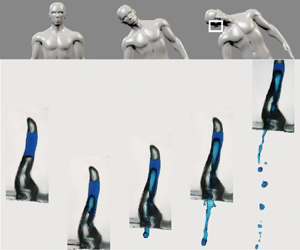
Figure 2(a,b) shows the ejection of water from an artificial human ear depending on the magnitude of acceleration,  $|a|$. Water stably stays in the artificial human ear with low acceleration (figure 2a), whereas the lower part of the water column becomes unstable and flows down with higher acceleration (figure 2b). This implies that a critical acceleration exists as the stable air–water interface breaks in the ear canal. We also characterize the water-dislodging dynamics using a simple geometry, i.e. a one-side closed hydrophobic glass tube. Figure 2(c–e) illustrates the sequential phenomena of water ejection. With low acceleration (figure 2c), a water bulge at the bottom air–water interface is formed during an initial deceleration (just after the collision with the spring). The bottom air–liquid interface does not break, but instead, it is restored back to its original position. As the acceleration increases (figure 2d), a water bulge cannot recoil back to its original position and starts to flow out without any cavitation bubble (Pan et al. Reference Pan, Kiyama, Tagawa, Daily, Thomson, Hurd and Truscott2017). In that case, the acceleration is denoted as the critical acceleration, $a_{cr}$. At even higher acceleration (figure 2e), a water bulge is further stretched, and thus, a much larger amount of water can be ejected.

Figure 2. Temporal evolution of a water drop inside a polydimethylsiloxane (PDMS) ear replica when (a)  $|a|=77\,{\rm m}\,{\rm s}^{-2}$ and when (b) $|a|=242\,{\rm m}\,{\rm s}^{-2}$. Here, the 30 % scaled-down-model of adult's ear canal is used and water is placed 15 and 25 mm above the exit of ear canal. (c–e) Image sequences of the water movement inside a glass tube with an inner diameter of 2.4 mm, where water is placed 5 and 10 mm above the open end of the tube. The acceleration is 108, 129 and 242 m s $^{-2}$ for panels (c–e), respectively. The dashed lines in the second image of panel (e) indicate a difference in the upper interface of the water column. This shows that the volume of air above the upper air–water interface is expanding during the collision. Corresponding movies 2–6 are included in the supplementary material.
5. Expansion of an upper air cavity to resist water ejection
Figure 2(c–e) shows how the upper interface of the water column (i.e. the lower interface of the air cavity) gets lower during the deceleration of the artificial ear. Since the air cavity above the water column is sealed by the closed top, the downwards displacement of the upper interface indicates that the air cavity volume increases during impact. Therefore, the air cavity decreases its internal pressure so that the lowered pressure pulls up the water column and consequently resists the ejection of water. To estimate the magnitude of air expansion, we balance an acceleration force,  $\rho (a+g)L_l({\rm \pi} R^2)$, with the resisting force, $(p_0-p_{min}){\rm \pi} R^2$, where $\rho$ is the water density, $L_l$ is the length of the water column and $R$ is the inner radius of the tube. We assume that the effect of dynamic pressure is negligible since the ratio of acceleration to dynamic forces, $\rho (a+g)L_l/[\rho (L_u/t_i)^2]$, is of the order of $10^3$. Here, $p_0$ represents the initial pressure and $p_{min}$ represents the pressure when the ear canal reaches its lowest position, $p(t=T_i/2)$. By assuming the adiabatic expansion of the air column and $\Delta L_u\ll L_a$ with $\Delta L_u$ being the vertical change of the position of the upper interface and $L_a$ being the initial length of the upper air column, the pressure change, $p_0-p_{min}$, can be approximated as $\varGamma p_0\Delta L_u/L_a$ as the leading order term with $\varGamma$ being the adiabatic constant ( $\varGamma =1.4$ for air). Therefore, the ratio of air cavity length to liquid length becomes
 \begin{equation} \frac{\Delta L_u}{L_a} \propto \frac{1}{\varGamma}\frac{\rho gL_l}{p_0}\left(1+\frac{a}{g}\right). \end{equation}
According to the above equation, the scattered data of the vertical change in the air cavity length in figure 3(c) are collapsed into a single line of (5.1) as shown in figure 3(d). The system mentioned above is the small-scale counterpart of the dynamics of emptying a bottle, where a similar coupling between the air compressibility and the liquid outflow is also observed (Clanet & Searby Reference Clanet and Searby2004).

Figure 3. (a) Acceleration,  $|a|$, versus the vertical length of water, $L_l$, with the tube having an inner diameter of 2.4 mm where the vertical length of the air cavity, $L_a$, is fixed to be 15 mm. (b) Acceleration, $|a|$, versus the vertical length of the air cavity, $L_a$, with the tube having an inner diameter of 4.6 mm where the length of the water, $L_l$, is maintained to be 10 mm. Here, closed and open symbols represent the ejection and the non-ejection of the water drop during the impact. (c) Changes in the vertical position of the upper air–liquid interface, $\Delta L_u$, versus acceleration, $|a|$, where different tube diameters and different lengths of the water column are tested. (d) $\Delta L_u/L_a$ plotted based on (5.1).
6. Rayleigh–Taylor instability
A fluid interface is stable when a fluid with a low density stays above another fluid with a high density. However, our system of interest is reversed (a fluid with high density, i.e. a water drop, placed above a fluid with low density, i.e. air) so that the Rayleigh–Taylor instability (Rayleigh Reference Rayleigh1882; Taylor Reference Taylor1950) would explain the water ejection dynamics. Figure 2 shows that the water ejection begins by forming a bulge at the lower water–air interface. Here, the classical Rayleigh–Taylor instability is modified to predict the critical acceleration with an air cavity behind. The ejection of the water column is driven by an inertial force but resisted by a surface force. The inertial force of the water column can be scaled by  $\rho R^{\prime 3}a$, where $R^\prime$ denotes the radius of the bulge (see the inset of figure 2d). Then, the resisting force can be estimated as $\gamma R^\prime$. Mass conservation shows that the bulge volume balances with the volume change in the air cavity, thereby estimating the radius of bulge curvature as $R^\prime \sim \Delta L_u^{1/3}R^{2/3}$. By balancing the driving and resisting forces together with the above $R^\prime$ relation, we simply get the following relation of critical acceleration for the water removal:
 \begin{equation} a_{cr}\sim\left(\frac{\gamma}{\rho}\right)^{3/5}\left(\frac{\varGamma p_0}{\rho}\right)^{2/5} \left( \frac{1}{L_l L_a R^{2}} \right)^{2/5}. \end{equation}
It is worth noting that we obtain a similar relation by calculating the dispersion relation of a cylindrical interfacial wave (see Appendix B).
Figure 4(a) shows the critical acceleration in terms of the liquid volume. Based on (6.1), we re-scale the  $x$-axis and find that all critical acceleration values are collapsed into a single line, as shown in figure 4(b). Moreover, (6.1) shows that a water column hardly gets removed, especially when a small amount of water is trapped just beneath the ear drum and/or when the radius of the ear canal is small. It implies that the forceful motion of head shaking can be dangerous for infants and children since the critical acceleration value becomes large due to the small size of their ear canal. Once the acceleration exceeds the critical value, water begins to flow out of the ear canal and the ejection volume appears to be proportional to $\Delta L_uD^2$ (see Appendix C).

Figure 4. (a) Experimentally measured critical acceleration,  $|a_{cr}|$, versus the volume of the liquid inside an ear canal, $V_L$, where different liquids and tube radii are tested as listed in the right legend. Circles and rectangles represent experimental results using glass tubes and PDMS replicas of a human ear canal, respectively. (b) $|a_{cr}|$ plotted based on (6.1).
7. Conclusions
In this study, we manufactured artificial ear canals similar to those of younger children and adults and performed ear shaking experiments. Our experiments revealed the dynamics of an artificial ear canal partially filled with water. The critical acceleration for the lodged water to flow out was measured in terms of canal size, acceleration, and location and volume of water. We developed a theory of modified Rayleigh–Taylor instability by considering a resisting pressure arising from the expansion of the upper air cavity and analytically predicted the critical acceleration. We showed that the critical acceleration strongly depends on the size of the ear canal, the volume and location of the trapped water. Our experiments were in good agreement with the theoretical predictions.
More importantly, our study implies that the critical acceleration, especially in young children and infants, could grow to 14 $g$ due to their narrow ear canals. Figure 5 illustrates the typical value of critical linear acceleration for brain injuries (concussion, subconcussive impact and symptomatic impact) for juveniles and adults. Our estimated critical acceleration, 14 $g$, is not small compared to other critical accelerations for brain injuries ( $|a_{cr}|\approx 14g$ for concussion during rugby (King et al. Reference King, Hume, Gissane and Clark2016), $|a_{cr}|\approx 16g$ for heading in soccer with subconcussive impacts (Naunheim et al. Reference Naunheim, Bayly, Standeven, Neubauer, Lewis and Genin2003), $|a_{cr}|\approx 18g$ for subconcussive collision between football players (Rowson et al. Reference Rowson, Brolinson, Goforth, Dietter and Duma2009) and $|a_{cr}|\approx 4g$ for low-speed vehicle collision with brain-pain symptoms McConnell et al. Reference McConnell, Howard, Guzman, Bomar, Raddin, Benedict, Smith and Hatsell1993). Subconcussive impacts, where someone is exposed to several repeated impacts without immediate injury symptoms, can also lead to altered neurophysical impairments (Breedlove et al. Reference Breedlove, Robinson, Talavage, Morigaki, Yoruk, O'Keefe, King, Leverenz, Gilger and Nauman2012; Talavage et al. Reference Talavage, Nauman, Breedlove, Yoruk, Dye, Morigaki, Feuer and Leverenz2014). Therefore, shaking the head aggressively to remove water can have long-term effects on the brain similar to the brain injuries of subconcussive impacts. In conclusion, head-jerking motions must be avoided especially for infants and young children.

Figure 5. Comparison of linear acceleration of the head depending on various situations (McConnell et al. Reference McConnell, Howard, Guzman, Bomar, Raddin, Benedict, Smith and Hatsell1993; Varney & Varney Reference Varney and Varney1995; Naunheim et al. Reference Naunheim, Bayly, Standeven, Neubauer, Lewis and Genin2003; Pellman et al. Reference Pellman, Viano, Tucker and Casson2003; Withnall et al. Reference Withnall, Shewchenko, Gittens and Dvorak2005; Guskiewicz et al. Reference Guskiewicz, Mihalik, Shankar, Marshall, Crowell, Oliaro, Ciocca and Hooker2007; Rowson et al. Reference Rowson, Brolinson, Goforth, Dietter and Duma2009; Mihalik et al. Reference Mihalik, Blackburn, Greenwald, Cantu, Marshall and Guskiewicz2010; Crisco et al. Reference Crisco, Wilcox, Machan, McAllister, Duhaime, Duma, Rowson, Beckwith, Chu and Greenwald2012; Daniel, Rowson & Duma Reference Daniel, Rowson and Duma2012; Hanlon & Bir Reference Hanlon and Bir2012; Daniel, Rowson & Duma Reference Daniel, Rowson and Duma2014; Wilcox et al. Reference Wilcox, Beckwith, Greenwald, Raukar, Chu, McAllister, Flashman, Maerlender, Duhaime and Crisco2015; King et al. Reference King, Hume, Gissane and Clark2016). There are three different types of impact: concussion impact in red circle, sub-concussive impact in yellow square and symptomatic impact in orange diamond. A grey band shows the range of critical acceleration of removing water out of the ear canal from infants to adults.
As alternatives to shaking the head, well-known home remedies include blowing air into the nose (Yale Reference Yale2005; Williamson et al. Reference Williamson, Vennik, Harnden, Voysey, Perera, Kelly, Yao, Raftery, Mant and Little2015) and inserting a few drops of vinegar into the ear (Nuttall & Cole Reference Nuttall and Cole2004; Djalilian Reference Djalilian2013). Here, the first air-blowing method can increase the internal pressure of the middle ear by pressurizing air in the eustachian tube from the nose. Then, the elasticity of the TM allows the membrane to buckle towards the external ear (Gaihede, Liao & Gregersen Reference Gaihede, Liao and Gregersen2007), which could increase the pressure of the air column and finally lower the critical acceleration. The second remedy of using vinegar can reduce the surface tension coefficient of the trapped water since the vinegar is miscible with water and has a low surface tension. Similarly, using a hair dryer into the ear canal also lowers surface tension by increasing the water temperature. Thus, other home remedies help to remove water trapped inside human ear canals, which is well explained by our theory.
Supplementary movies
Supplementary movies are available at https://doi.org/10.1017/jfm.2023.309.
Acknowledgements
The authors thank Ms. K. Averett for her initial contribution to this study.
Funding
This work was partially supported by the National Science Foundation (grant no. CMMI-2042740 and no. CBET-2002714) and by the National Research Foundation of Korea (grant no. 2022R1F1A1076192 and no. 2020R1A5A8018822) via PNU EPIC.
Declaration of interests
The authors report no conflict of interest.
Appendix A. Three-dimensional and CT-scanned structures of ear canal
Figure 6(a) shows a 3-D structure of a human head with the ear canal (grey), and figure 6(b) a zoomed top view of CT-scan image showing the internal structure of the right ear canal. The ear canal gets narrower as it approaches the tympanic membrane. The image source is described in § 3, where the skull image is achieved via overlapping multiple CT-scanned images.

Figure 6. (a) Image showing a 3-D structure of the ear canal with a human skull. (b) CT-scanned right ear canal, where the image is seen from the top of the head.
Appendix B. Dispersion relation of a modified Rayleigh–Taylor instability
We consider the interfacial deformation on the bottom liquid–air surface, which has a solution of the Bessel function in the radial ( $r$) direction and sinusoidal functions in the azimuthal ( $\theta$) direction. The axial velocity profile of the bottom liquid–air interface, $u_z$, can be approximated as
 \begin{equation} u_z=\tilde{u}_z\textrm{e}^{{-}kz+st+{\rm i}m\theta}{\rm J}_m(kr), \end{equation}
where  $z$ and $t$ represent a vertical coordinate and time, respectively. Here, $\tilde {u}_z$, $k$,
$k$,  $s$ and $m$ correspond to the velocity magnitude, wavenumber, growth rate and an integer index ( $m=0,1,2,3,\ldots$), respectively. For the Bessel function of the first kind, ${\rm J}_m(kr)$, we considered the simplest wave mode ( $m=0$) which is consistent with our experimental observations of the interfacial deformation during the ejection of a trapped water drop (see figure 2d). Then, the displaced volume by the expansion of the air column, ${\rm \pi} R^2\Delta L_u$, should be equal to the volume of liquid bulge at the lower liquid–air interface, $\iiint u_z\,{\rm d}t(r\,{\rm d}r)\,{\rm d}\theta$. By plugging (5.1) and (B1) into the volume conservation relation, we get
 \begin{equation} {\rm \pi}R^2\frac{\rho}{\varGamma p_0}L_l L_a|a|=\tilde{u}_z\frac{1}{s}\left. \textrm{e}^{{-}kz+st} \right|^{t^*}_02{\rm \pi}\int_0^R {\rm J}_0(kr)r\,{\rm d}r . \end{equation}
It can be then expressed as
 \begin{equation} sk^2=\frac{\varGamma p_0}{\rho}\frac{c}{R^2L_l L_a|a|}, \end{equation}
where  $c\propto \tilde {u}_z\int _0^RJ_0(kr) \,kr\,d(kr)$.
To obtain the explicit expression of  $s$ in terms of $k$, we first considered the axial displacement of the lower liquid–air interface, $\zeta$, as
 \begin{equation} \zeta=\tilde{\zeta}\textrm{e}^{st}{\rm J}_0(kr). \end{equation}
Then, the linearized Euler equation together with Young–Laplace equation yields the following relation:
 \begin{equation} \rho\partial_tu_z={-}\partial_z(-\gamma\partial_{rr}\zeta+ \rho a\zeta). \end{equation}
Here, we use a small slope approximation ( ${\rm d}\zeta /{\rm d}r\ll 1$). Next, the kinematic boundary condition at the lower liquid–air interface is further considered as
 \begin{equation} u_z=\partial_t\zeta. \end{equation}
Using (B1), (B4), (B5) and (B6), we can obtain the dispersion relation as
 \begin{equation} s^2=ak-\frac{\gamma}{ \rho}k^3 . \end{equation}
This is known as the Rayleigh–Taylor instability. The maximum occurs when  $\partial s^2/\partial k=0$. Then, we get the most unstable wavenumber, $k^*=\sqrt {\rho |a|/(3\gamma )}$, which finally results in the following relation of the most unstable modal number, $s^*$:
 \begin{equation} s^*=\sqrt{\frac{2}{3}|a|k^*}. \end{equation}
By plugging (B8) into (B3), we can finally get the relation of critical acceleration for ejecting a water drop inside the ear canal as
 \begin{equation} a_{cr}^{11/10} \sim \tilde{u}_z^{2/5}\left(\frac{\gamma}{\rho}\right)^{1/2}\left(\frac{\varGamma p_0}{\rho}\right)^{2/5}\left(\frac{1}{L_lL_aR^2}\right)^{2/5}. \end{equation}
One can see a similarity between (B9) and (6.1) despite different derivations. Equation (B9) is from the dispersion relation using a perturbation method, whereas (6.1) is based on the scaling argument. The small differences between the two models originate from integrating the the first kind of Bessel function in (B2).
Appendix C. Ejection volume of dislodging water
Figure 7(a) shows the ejection volume of the dislodging water,  $V_{ejection}$, versus acceleration, where the experimental value of $V_{ejection}$ is obtained via analysing images before and after the first impact. Since the ejection of water occurs at the lower water–air interface, we consider $V_{ejection}$ as
 \begin{equation} V_{ejection}=\int_0^{T_i}u_z\,{\rm d}A. \end{equation}
By considering the continuity,  $u_z$ scales as $\dot {\Delta L_u}$, which leads to the following relation: $V_{ejection}\sim \Delta L_uR^2$. Using (5.1), we can obtain the following relation as
 \begin{equation} V_{ejection}\sim\left(\frac{\rho}{\varGamma p_0}\right) L_lL_aR^2|a|. \end{equation}
Based on (C2), we rescale the  $x$-axis in figure 7(b) and find that the ejection volume follows a single line. Deviations from the diagonal line may originate for the following reasons. First, the scaling model above explains the initial instability, but does not consider long-term behaviours. As shown in the third image in figure 2(e), a thin jet is formed and drags more water out of the tube by inertia. Second, water droplets could stick to the inner wall of the ear canal right after the first impact, as shown in the last image of figure 2(d). Additionally, the water droplets adjacent to the lower water–air interface could be absorbed into the bulk due to surface tension. All of these contribute to the uncertainties of $V_{ejection}$.

Figure 7. (a) Experimentally measured ejection volume of dislodging water,  $V_{ejection}$, versus acceleration, $|a|$, where different liquid lengths and tube radii are tested. (b) $V_{ejection}$ versus (C2).


 Open access