


1. Introduction
Bio-mimicking is an innovative way of designing highly efficient robotic platforms for numerous engineering applications. Hence, understanding physical mechanisms employed by natural aquatic species is important to design next-generation autonomous swimming robots. An oscillating foil presents a generic model for the motion used by fish to propel (Anderson et al. Reference Anderson, Streitlien, Barrett and Triantafyllou1998). Various studies on such dynamic systems were conducted by researchers in the past few decades, addressing different aspects of the associated wake mechanics and hydrodynamic performance of oscillating foils. Triantafyllou, Triantafyllou & Grosenbaugh (Reference Triantafyllou, Triantafyllou and Grosenbaugh1993) argued that the Strouhal number, defined as  $St={f}{A}/{U_{\infty }}$, was one of the governing parameters in fish-like swimming problems. Here, $f$ denotes the oscillation frequency, $A$ is the amplitude of oscillations and $U_{\infty }$ shows the free-stream flow velocity. They showed that, for an oscillating foil, the Strouhal number of highest propulsive efficiency overlapped with that of the natural swimming motion of for many fish, cetaceans and marine mammals.
Fish schooling is defined as a behaviour seen in many fish species that appears as the aggregation of a number of individuals and their collective navigation in the flow. Various reasons were propounded by evolutionary biologists and zoologists to explain this habit. These include, but are not limited to, improved attempts for finding a mate, effective defence strategy by confusing predators and better chances of finding prospection. A fundamental question is raised in the minds of engineers interested in bio-inspiration: ‘Could coordinated swimming enhance the propulsive performance of an individual swimmer?’ One of the pioneer studies, which addressed this question, was presented by Weihs (Reference Weihs1973). They argued, based on a highly idealized, two-dimensional (2-D) and inviscid model, that individuals in schooling formation might enjoy hydrodynamic benefits if the spacing and synchronization between swimmers was adequately adjusted. Hemelrijk et al. (Reference Hemelrijk, Reid, Hildenbrandt and Padding2015) numerically simulated viscous flows over undulating fish for a range of separation distances for four different infinite schools: diamond, side-by-side, in-line and rectangular. It was demonstrated that entire schooling formations, except very dense ones with side-by-side formations, resulted in improved swimming efficiency. Daghooghi & Borazjani (Reference Daghooghi and Borazjani2015) conducted large-eddy simulations of self-propelled synchronized mackerels in a variety of infinite rectangular schooling patterns. They observed that schooling fish enjoyed significant enhancements in swimming speed without more power requirements. They achieve this through exploitation of the channeling effect. Ashraf et al. (Reference Ashraf, Godoy-Diana, Halloy, Collignon and Thiria2016, Reference Ashraf, Bradshaw, Ha, Halloy, Godoy-Diana and Thiria2017) experimentally approached this problem by examining the swimming of two red nose tetra fish in a shallow-water tunnel with controlled velocity. By tracking kinematics of fish using stereoscopic video recordings, it was demonstrated that the possibility that fish locomote in a side-by-side configuration and synchronize their tail beat frequencies was strongly correlated with the increasing speed of the water. This suggests that in-phase or out-of-phase synchronization of the collectively swimming fish in parallel with a proper spacing provides intensified propulsive performance during demanding flow conditions. It is evident from the literature that collective swimmers gain hydrodynamic benefits from multi-body arrangements. However, the physical mechanisms, causing the performance enhancement with applications in underwater propulsor design, fish schools and other similar engineering systems, have not been thoroughly revealed yet.
Latest developments in the field of bio-inspired swimming accelerated the efforts to examine the propulsive performance of individual members in fish schools from different perspectives. Measurements of energy consumed by a pair of fish-like robots developed by Li et al. (Reference Li, Nagy, Graving, Bak-Coleman, Xie and Couzin2020) displayed that follower fish in a staggered configuration gained energy benefits if the phase difference between tail beat frequencies was linearly conformed with their longitudinal distance. They referred to this phenomenon as vortex phase matching. It was further validated through experiments with real fish that the follower utilized this strategy in order to exploit hydrodynamic interactions to reduce the energy cost during swimming. Later, Li et al. (Reference Li, Ravi, Xie and Couzin2021) focused on the swimming of bio-mimetic robots in side-by-side configurations at a range of phase differences and revealed that both swimming speed and efficiency of the pair were enhanced compared with a single swimmer for the entire range, where in-phase and out-of-phase swimming could be employed to maximize efficiency and speed, respectively. A recent study by Yu et al. (Reference Yu, Liu, Wang, Liu, Lu and Huang2022) examined self-organization patterns of self-propelled undulatory swimmers using a deep-reinforcement-learning technique. For two in-line swimmers with very small gap distances between them, side-by-side arrangements spontaneously emerged when the solver was set to optimize the swimming efficiency of both individuals. The same solution strategy was applied to fish schools comprised of three to six bodies. It resulted in the formation of optimal subgroups with two to four individuals. For all schooling configurations, swimmers in schools yield considerably enhanced efficiency compared with a single swimmer. Most recent studies confirm that collective locomotion outperforms a solitary one as long as the swimming conditions are appropriately disposed. Despite extensive studies on hydrodynamic benefits of multi-foil arrangements, there is not a clear understanding of the wake topology and change of vortex dynamics associated with this multi-foil system.
Fish schools are often modelled using multiple oscillating rigid hydrofoils arranged in different configurations due to the simplicity that it offers. Boschitsch, Dewey & Smits (Reference Boschitsch, Dewey and Smits2014) carried out experiments on the propulsive performance and wake structures of two pitching foils in an in-line configuration for a range of separation distances and phase differences. They observed that both the performance and wake structures of the front foil were affected by the presence of the downstream foil only for considerably small separation distances. They distinguished two different wake modes: branched and coherent. In the coherent mode a single vortex street is formed behind the follower foil whose time-averaged wake corresponds to a single high-momentum jet. The branched mode, on the other hand, has two angled high-momentum jets in its time-averaged wake. The peaks in the thrust, power and efficiency coincide with the coherent mode wakes while the branched mode wakes are associated with the troughs. Recently, Lagopoulos, Weymouth & Ganapathisubramani (Reference Lagopoulos, Weymouth and Ganapathisubramani2020) focused more on the wake deflection and production of side force by simultaneously heaving and pitching foils in an in-line configuration. They identified three distinct vortex patterns in the wake and showed that wake deflection introduced by the upstream foil could be eliminated due to the presence of the downstream body. Meng et al. (Reference Meng, Chen, Zhang and Chen2022) took a further step and simulated flows over multiple flapping foils in in-line configurations. For three wings, they demonstrated that thrust of the system was optimized for a separation distance of two chord lengths with the third wing generating the most thrust. Later, they examined the system with four, five, six and seven wings, but observed that a further increase in the number of wings did not translate into any alteration in the average thrust produced by the group.
There is a consensus in the literature that parallel foils exhibit reduced thrust generation and power requirement compared with a single foil for in-phase oscillations (Dewey et al. Reference Dewey, Quinn, Boschitsch and Smits2014; Huera-Huarte Reference Huera-Huarte2018; Gungor & Hemmati Reference Gungor and Hemmati2021; Yucel, Sahin & Unal Reference Yucel, Sahin and Unal2022). However, Dewey et al. (Reference Dewey, Quinn, Boschitsch and Smits2014) and Huera-Huarte (Reference Huera-Huarte2018) estimated improved efficiency for parallel foils, whereas Yucel et al. (Reference Yucel, Sahin and Unal2022) found that the efficiency of a single foil was greater. Gungor & Hemmati (Reference Gungor and Hemmati2021) conducted a comprehensive analysis and revealed that  $St$ and $Re$ had a strong impact on the efficiency of the system. For smaller $St$ and $Re$, single foils tend to show superior performance, whereas parallel foils outperform them for greater values of $St$ and $Re$. For out-of-phase oscillations, previous studies agree that parallel foils produce considerably larger thrust at the cost of enhanced power requirement, which results in the nearly similar efficiency (Dewey et al. Reference Dewey, Quinn, Boschitsch and Smits2014; Huera-Huarte Reference Huera-Huarte2018; Gungor & Hemmati Reference Gungor and Hemmati2021; Yucel et al. Reference Yucel, Sahin and Unal2022).
Dewey et al. (Reference Dewey, Quinn, Boschitsch and Smits2014) qualitatively examined vortex patterns of in-phase, mid-phase and out-of-phase pitching foils in side-by-side configurations for a fixed separation distance and Strouhal number. They then proposed models of wake development for each case. To this end, it was shown that in-phase, out-of-phase and mid-phase pitching foils produced merging symmetric, diverging symmetric and asymmetric wakes, respectively. Likewise, numerical simulations of Huera-Huarte (Reference Huera-Huarte2018) demonstrated that the foils in staggered arrangements produced asymmetric wakes for both in-phase and out-of-phase oscillations. More recently, Gungor & Hemmati (Reference Gungor and Hemmati2020) reported on numerical studies of in-phase and out-of-phase pitching foils in parallel arrangements at different Strouhal numbers that maintain a constant gap between them. They showed that the two foils produced quasi-steady symmetric wakes for both phase differences at low  $St$, whereas asymmetric-to-symmetric and symmetric-to-asymmetric transitions were observed in the wake at high $St$ for in-phase and out-of-phase oscillations, respectively. A similar symmetry breaking phenomenon in the wake of foils, performing out-of-phase oscillations in a parallel configuration, was observed by Bao et al. (Reference Bao, Zhou, Tao, Peng, Zhu, Sun and Tong2017) and Zhang et al. (Reference Zhang, He, Wang and Zhang2018). However, they demonstrated the asymmetric wake at a single time instant without examining the transient formation process of their asymmetry. Ambolkar & Arumuru (Reference Ambolkar and Arumuru2022) numerically studied two parallel foils, which were not equal in size for a range of pitching frequencies and phase differences. They showed that vortex streets shed from the foils were separated from each other as a result of their deflections in opposite directions at higher frequencies, whereas they merged in the near wake at lower frequencies for all phase differences. For intermediate oscillations, on the other hand, the merger of the vortex streets occurred only for smaller phase differences. Nonetheless, vortex patterns presented in these studies mostly rely on qualitative approaches. Hence, a mathematical model that provides quantitative classification to these wake topologies is not yet available. Furthermore, the physical mechanisms that result in the formation of distinct wake patterns are not yet understood.
At low Strouhal numbers, oscillating foils produce the well-known Bénard–von Kármán (BvK) vortex street. The wake transitions to reverse the BvK vortex street with increasing  $St$ (Koochesfahani Reference Koochesfahani1989). A further increase in the value of $St$ triggers the symmetry breaking process in the wake, resulting in the formation of deflected (asymmetric) BvK streets (Jones, Dohring & Platzer Reference Jones, Dohring and Platzer1998). This phenomena has been extensively investigated in the literature for single foils (von Ellenrieder & Pothos Reference von Ellenrieder and Pothos2008; Liang et al. Reference Liang, Ou, Premasuthan, Jameson and Wang2011; Cleaver, Wang & Gursul Reference Cleaver, Wang and Gursul2012). Godoy-Diana, Aider & Wesfreid (Reference Godoy-Diana, Aider and Wesfreid2008) demonstrated that the flow parameters of flapping locomotion in nature coincides with the parameters of oscillating foils that produce deflected wakes. They further conjectured that natural swimmers and fliers could either utilize deflected wakes as their maneuvering strategy or avoid them during forward locomotion. Godoy-Diana et al. (Reference Godoy-Diana, Marais, Aider and Wesfreid2009) argued that even though three-dimensional (3-D) effects influence vortex dynamics of oscillating foils, the wake deflection was a quasi-two-dimensional (Q2D) phenomenon. The wake deflection occurred when self-advection of the first shed dipole was strong enough to divert the main flow and subsequent dipoles away from the wake centreline. Godoy-Diana et al. (Reference Godoy-Diana, Aider and Wesfreid2008) further proposed a model that quantitatively predicted wake deflection, considering the offset between dipolar velocity and advection velocity of the dipoles. Although $St$ has a significant influence on asymmetric characteristics of oscillating foils, the amplitude of the oscillation is observed to considerably affect the attributions of deflected wakes. Symmetry breaking is triggered in the wake of oscillating foils at noticeably high oscillation amplitude for a fixed $St$ (Godoy-Diana et al. Reference Godoy-Diana, Aider and Wesfreid2008). A further increase in the amplitude results in the transition from 2-D wake to 3-D wake, which suggests that transition from reverse BvK to deflected BvK is required for the formation of 3-D instabilities in the wake (Deng, Sun & Shao Reference Deng, Sun and Shao2015). Even though deflected wakes are extensively studied for single oscillating foils, their influence on the wake patterns and performance metrics of multi-foil arrangements still requires comprehensive analysis.
On the other hand, there are some conditions that inhibit the formation of deflected wakes. For instance, Marais et al. (Reference Marais, Thiria, Wesfreid and Godoy-Diana2012) investigated the influence of flexibility on the wake deflection characteristics of oscillating foils. They demonstrated that the formation of an asymmetric vortex street was hindered for flexible foils, although rigid foils produced deflected wakes under the same flow conditions. It is attributed to interactions between the shed vortices and flexible foils. Likewise, Calderon et al. (Reference Calderon, Cleaver, Gursul and Wang2014) showed that 3-D effects in the wake of finite span foils hindered wake deflection, which was observed for the effectively infinite span foils under the same flow conditions. Three dimensionality introduced by the tip vortex, which prevents the vortex coupling, and the symmetric circulation of interconnected vortex loops, which are due to the vortex topology of a finite span foil, are two underlying reasons that were provided for cancellation of the deflection.
Efficient propulsion through effective vorticity control implementation has been an great challenge in the engineering community for decades. Under the inviscid and incompressible flow assumption, trapping a free vortex on the upper surface of a 2-D wing is theoretically capable of increasing lift generation through the introduction of a low pressure region (Huang & Chow Reference Huang and Chow1982). An adequately stabilized spanwise vortex can enhance the coefficient of lift up to 10 times, which can be beneficial for the design of short takeoff and landing aircrafts (Rossow Reference Rossow1978). Saffman & Sheffield (Reference Saffman and Sheffield1977) calculated the exact solution for potential flow over a flat plate with a free line vortex positioned on the upper boundary and estimated highly improved lift generation. Leading edge vortices (LEVs) substantially impact and often dominate the wake of simultaneously heaving and pitching foils, where their development could extensively amplify the propulsive performance of foils depending on their formation and shedding. These all are influenced by the foil kinematics. For instance, amalgamation of an LEV and a trailing edge vortex (TEV), which coincides with high efficiency and improved thrust generation, occurs when vortical structures are controlled using various parameters of foil kinematics, such as the phase angle between heave and pitch,  $St$, the amplitude of the heave motion or the maximum angle of attack (Anderson Reference Anderson1996; Anderson et al. Reference Anderson, Streitlien, Barrett and Triantafyllou1998). Likewise, three distinct vortex patterns are formed behind the foil simultaneously heaving and pitching in the wake of a D-section cylinder (Gopalkrishnan Reference Gopalkrishnan1993; Gopalkrishnan et al. Reference Gopalkrishnan, Triantafyllou, Triantafyllou and Barrett1994; Shao & Pan Reference Shao and Pan2011). Implementation of active vorticity control by dictating the flow kinematics yields a constructive interaction mode, a destructive interaction mode and an expanding wake mode, which correspond to trough, peak and mixed responses in efficiency.
Natural swimmers and flyers are known to exploit physical mechanisms for their best interest to achieve the most efficient way to propel themselves in a fluid medium. Reattachment of LEVs, formed by the flow separation due to dynamic stall, on the upper surface of the wing of hawkmoths or fruit flies during the downstroke of flapping greatly contributes to lift production (Ellington et al. Reference Ellington, Van Den Berg, Willmott and Thomas1996; Birch & Dickinson Reference Birch and Dickinson2001; Bomphrey et al. Reference Bomphrey, Lawson, Harding, Taylor and Thomas2005). Although balancing the body weight with enhanced lift production plays a crucial role in insect flight, it constitutes insignificant adversity for aquatic animals, owing to the presence of strong bouyant forces. The main concern for aquatic swimmers is to overcome the drag exerted by water, which is three orders of magnitude denser than air. Borazjani & Daghooghi (Reference Borazjani and Daghooghi2013) carried out numerical simulations on self-propelled virtual swimmers with three different tail geometries inspired from the mackerel body. They demonstrated that an attached LEV is formed on the body during locomotion settings that resemble natural swimming conditions for most fish. Evolution of the LEV is remarked to consequentially influence the pressure distribution around the tail and the generated force for different tail shapes. In an experimental study, the propulsive force of actively swimming bottlenose dolphins was calculated using digital particle image velocimetry measurements of the vortex generated by the large amplitude fluke stroke of the dolphin (Fish et al. Reference Fish, Legac, Williams and Wei2014). Effect of body shape (mackerel body or lamprey body) and swimming kinematics (anguilliform or carangiform) on the hydrodynamics of self-propelled virtual body/caudal fin swimmers was numerically examined by Borazjani & Sotiropoulos (Reference Borazjani and Sotiropoulos2010) for a range of Reynolds numbers. It is noted that the form and kinematics of swimmers differently impact the swimming efficiency in viscous, transitional and inertial regimes. Liu et al. (Reference Liu, Ren, Dong, Akanyeti, Liao and Lauder2017) simulated a more complex model, which includes both fin–fin and body–fin interactions, by reconstructing body shape and kinematics of steady swimming crevalle jack using high-speed cameras. They demonstrated that posterior body vortices captured by the caudal fin strengthens LEVs around the fin, which produces most of the swimming thrust.
Although there are a few studies that demonstrate the development of vortex structures behind parallel foils, there are none that provide quantitative explanations for the vortex interactions in the wake. Furthermore, studies focusing on explaining vortex patterns in the wake mostly overlooked unsteady interactions and their impact on propulsive performance, which are expected at high  $St$. In this study we examine merged–separated characteristics of the vortex streets in the wake of pitching foils in a side-by-side arrangement at a range of $St$, phase differences, oscillation amplitudes and separation distances, inspired from fish schools. Outcomes of this study aim to strengthen our knowledge of the governing flow physics and control techniques for novel underwater propulsors operating in schooling configurations to attain superior swimming performance. The Reynolds number of the flow ( $Re=U_{\infty }c/\nu$, where $c$ is the chord length of the foil and $\nu$ is the dynamic viscosity of the fluid) is fixed at $4000$ considering wake patterns of oscillating foils reach a plateau after $Re\geq 1000$ (Das, Shukla & Govardhan Reference Das, Shukla and Govardhan2016) and their propulsive performance exhibits negligible alteration after $Re \geqslant 4000$ (Senturk & Smits Reference Senturk and Smits2019). Therefore, this paper aims to illuminate three novel points that are currently missing in the literature: (i) quantification and classification of vortex patterns behind two parallel pitching foils, (ii) the physical mechanisms governing the wake merging phenomenon and (iii) the influence of the merger on the propulsive performance of the system. For this purpose, this paper is structured as follows. A description of the dynamic system, composed of two pitching foils and our numerical set-up, is provided in § 2. Section 3 includes the results on the wakes of parallel foils and discussions concerning the vortex patterns and wake merging phenomena, which is followed by the main conclusions in § 4.
2. Methodology
The flow around two oscillating, rigid teardrop foils in a side-by-side configuration is numerically simulated using OpenFOAM. For this purpose, Navier–Stokes equations are directly solved using the pimpleDyMFOAM solver, which is an incompressible transient flow solver for systems requiring dynamic grids. The solver utilizes the PIMPLE algorithm, which is a hybrid of PISO (pressure-implicit with splitting operators) and SIMPLE (semi implicit method for pressure linked equations). The time-step size is adequately selected to limit the Courant number of the flow below 0.8 throughout the domain. It is achieved by using over 3500 time steps per oscillation cycle. The divergence terms of the Navier–Stokes equations are discretized using the upwind-biased, second-order accurate ‘linear upwind’ technique. A second-order implicit backward time method is employed for temporal terms. The convergence criterion, which is the residual of velocity components and pressure in the momentum equations, is set to  $10^{-5}$.
Both foils, foil 1 (lower foil) and foil 2 (upper foil), have chord lengths of  $c$ and semicircular leading edges with radii of $0.05c$. They perform a pure pitching motion, which is mathematically defined as
 \begin{gather} \theta_1(t)=\theta_0\sin(2{\rm \pi} ft), \end{gather}
 \begin{gather}\theta_2(t)=\theta_0\sin(2{\rm \pi} ft+\phi). \end{gather}
Here,  $\theta _0$ is the pitching amplitude, $t$ is time and $\phi$ is the phase difference between the two foils. The phase difference between the foils is varied from in-phase ( $\phi =0$) to out-of-phase ( $\phi ={\rm \pi}$) with increments of ${\rm \pi} /6$, and the pitching amplitude is fixed at $8^\circ$. However, simulations with $\theta _0$ = $5^\circ$, $11^\circ$ and $14^\circ$ are also performed for selected cases in order to ensure the validity of the analysis over a range of pitching amplitudes. This analysis reveals that classification of the wake topology remains consistent, while the ranges at which each topology is observed may differ with changing amplitude. This, however, would not concern the core analyses in the current study. A schematic representation of the pitching motion is provided in figure 1(a). The grid is morphed by the solver at each time step in order to ensure the pitching motion while maintaining its quality. The separation distance between the foils ( $d$) is varied from $0.5c$ to $2.5c$ with increments of $0.5c$ and is non-dimensionalized by $c$, i.e. $0.5< d^*=d/c<2.5$. Here, $St$ ranges from $0.15$ to $0.5$ for each value of $d^*$. This parametric space ( $d^*$ extend) is selected to provide a systematic variation in parameters, which also follows the experiments of Dewey et al. (Reference Dewey, Quinn, Boschitsch and Smits2014) and includes the range of separation distances between two red nose tetra fish, synchronously swimming in a side-by-side arrangement, during fish tank experiments by Ashraf et al. (Reference Ashraf, Godoy-Diana, Halloy, Collignon and Thiria2016, Reference Ashraf, Bradshaw, Ha, Halloy, Godoy-Diana and Thiria2017). The $St$ space covers the formation of BvK, reverse BvK and deflected BvK regimes in the wake of single oscillating foils (Godoy-Diana et al. Reference Godoy-Diana, Aider and Wesfreid2008) and the natural swimming $St$ of various fish species (Triantafyllou et al. Reference Triantafyllou, Triantafyllou and Grosenbaugh1993). The extent of the parameter space used in the study is summarized in table 1.

Figure 1. Demonstration of the (a) pitching motion, (b) 2-D computational domain with boundary conditions (not to scale).
Table 1. Parametric space of the study.

A computational domain, similar to the one reported in our previous work (Gungor & Hemmati Reference Gungor and Hemmati2021; Gungor, Khalid & Hemmati Reference Gungor, Khalid and Hemmati2021) is employed in this study, which follows the experiments of Dewey et al. (Reference Dewey, Quinn, Boschitsch and Smits2014). It extends  $30c$ in the streamwise ( $x$) direction and $16c$ in the cross-flow ( $y$) direction. Also, the leading edge of the foils are placed $8c$ away from the inlet. The Neumann condition for both pressure and velocity are applied at the outlet boundary, while a uniform velocity ( $u=U_{\infty }, v=0, w=0$) is prescribed to the inlet boundary. Boundary conditions for the upper and lower walls and foil surfaces are selected to be slip and no-slip, respectively.
A non-homogeneous spatial grid, consisting of  $7.87\times 10^5$ hexahedral elements, is generated to simulate the flow. The grid is most refined around the foils with $600$ nodes on the surface of each foil, which is consistent with the numerical set-up of Senturk & Smits (Reference Senturk and Smits2019). The grid size expands towards the boundaries without exceeding the expansion ratio of $1.03$ in the entire computational domain. Sensitivity analyses for grid, time-step, and domain sizes as well as a validation study of our computational methodology are provided in Gungor et al. (Reference Gungor, Khalid and Hemmati2021). More details of the presently utilized grid around the foils are presented in figure 2.

Figure 2. Details of the spatial grid around the (a) leading edge, (b) trailing edge during the upstroke ( $\theta =8^{\circ }$), (c) trailing edge during the downstroke ( $\theta =-8^{\circ }$).
Two-dimensional versus three-dimensional simulations are an important numerical complexity that can have implications on wake dynamics at high  $Re$ flow conditions. To this effect, we carried out 3-D sensitivity studies to confirm that the underlying physics of coherent structures in the flow, including wake deflection, wake merging and vortex interactions, follow a 2-D or Q2D mechanism (Godoy-Diana et al. Reference Godoy-Diana, Aider and Wesfreid2008, Reference Godoy-Diana, Marais, Aider and Wesfreid2009; Dewey et al. Reference Dewey, Quinn, Boschitsch and Smits2014; Shoele & Zhu Reference Shoele and Zhu2015; Lagopoulos et al. Reference Lagopoulos, Weymouth and Ganapathisubramani2020). Deng et al. (Reference Deng, Sun, Teng, Pan and Shao2016) notes that the 2-D to 3-D transition in the wake of pure pitching foils occurs at considerably high $St$, which excludes the parameter space employed here. Contour plots in figure 3 compare coherent structures, and their interactions, along the centre $xy$ plane of the wake of in-phase pitching foils at $Re=4000$, $St=0.3$ and $d^*=1$ with those from 2-D simulations. These results confirm that 2-D and 3-D simulations render very similar results in terms of coherent structures, wake dynamics and interactions related to merging. Moreover, it has been previously established that there are no significant variations observed between 2-D and 3-D cases in studying propulsive performance of pure pitching foils at moderate $St$, e.g. thrust, efficiency and power (Zurman-Nasution, Ganapathisubramani & Weymouth Reference Zurman-Nasution, Ganapathisubramani and Weymouth2020). This range comprises $St$ of the flow examined in the current study. Note that the impact of three dimensionality on wake structures (Deng et al. Reference Deng, Sun, Teng, Pan and Shao2016) and performance (Zurman-Nasution et al. Reference Zurman-Nasution, Ganapathisubramani and Weymouth2020) becomes remarkable at relatively lower $St$ for pure heaving foils.

Figure 3. Comparing contour plots of the spanwise component of vorticity ( $\omega _z$) of in-phase pitching foils between (a) 2-D and (b) 3-D simulations for $Re=4000$ and $St=0.3$ at $t=10P$. Here, ‘ $P$’ is the period of pitching cycle. The 3-D case renders results on the mid $xy$ plane.
The cycle-averaged coefficients of thrust ( $\widetilde {C_T}$) and power ( $\widetilde {C_P}$) together with Froude efficiency ( $\eta$) are calculated to discuss propulsive performance of the foils. These parameters are defined as
 \begin{gather} \widetilde{C_T}=\frac{\widetilde{F_x}}{{\tfrac{1}{2}} \rho U_\infty^2 sc}, \end{gather}
 \begin{gather}\widetilde{C_P}=\frac{\widetilde{M_z}\dot{\theta}}{{\tfrac{1}{2}} \rho U_\infty^3 sc}, \end{gather}
 \begin{gather}\eta=\frac{\widetilde{C_T}}{\widetilde{C_P}}. \end{gather}
Here,  $\widetilde {F_x}$ is the streamwise force applied by the foil to the fluid, $\widetilde {M_z}$ is the moment in the $z$ direction applied to the foil, $\rho$ is fluid density and $s$ is the span of the foil. Besides, $\widetilde {F_x}$ and $\widetilde {M_z}$ are averaged within each oscillation cycle over at least 3500 time steps.
3. Results and discussion
We begin our analysis with examining vortex dynamics and wake interactions of parallel pitching foils. In a previous study (Gungor & Hemmati Reference Gungor and Hemmati2020) we examined transient wake developments of foils, performing in-phase and out-of-phase pitching in side-by-side configurations for  $St=0.25\unicode{x2013}0.5$ and $d^*=1$ at $Re=4000$. It was demonstrated that wake structures at low $St$ showed quasi-steady characteristics and were in perfect agreement with the findings of Dewey et al. (Reference Dewey, Quinn, Boschitsch and Smits2014), i.e. merging symmetric wake for in-phase pitching and diverging symmetric wake for out-of-phase pitching foils. However, wake structures and propulsive performance of both in-phase and out-of-phase pitching foils were observed to be highly transient at high $St$. The wake of in-phase pitching foils initially consisted of two deflected vortex streets parallel to each other. These streets merged after some time and formed a symmetric wake. The merging process coincides with the enhancement in time-averaged thrust and efficiency of the foils. The opposite phenomena was observed in the wake of out-of-phase pitching foils. The foils initially produced diverging symmetric wakes whose symmetry was broken after several oscillation cycles. Here, we expand the parametric space to classify vortex patterns, which elucidate active flow control techniques possibly employed by natural swimmers, to gain a desired hydrodynamic performance. Furthermore, we also present a quantitative explanation for underlying physical mechanisms of the wake merging phenomenon.
3.1. Classification of vortex patterns
We identify three distinct vortex patterns in the wake of parallel pitching foils (side-by-side configuration) for the given parametric space. Merged–separated characteristics of the wakes were taken into consideration when classifying the wake in figure 4. Here, a merged wake corresponds to the vortex topology that involves the vortex streets shed by upper and lower foils merging in mid-wake and forming a single street, which constitutes a new flow configuration. In separated wakes, on the other hand, upper and lower vortex streets do not amalgamate with each other. Separated wakes of in-phase pitching foils consist of two parallel vortex streets whereas a ‘v-shaped’ diverging configuration is observed in the separated wakes of out-of-phase pitching foils (see figure 4b,d). In both merged and separated wakes, vortex patterns are formed within several pitching cycles and their merged–separated features remain unchanged during the next oscillation cycles without altering significantly (compare  $t_1=14P$ and $t_2=20P$ of figures 4(a), 4(b) and 4(d), where P is the period of the pitching cycle). Note that out-of-phase pitching foils at $St=0.5$ (not shown here for brevity) experience symmetric to asymmetric transition (Gungor & Hemmati Reference Gungor and Hemmati2020). However, its wake remains separated throughout the process. Conversely, transitional-merged wakes undergo distinct separation and merging stages, primarily transitioning from the former to the latter configuration. As explained earlier, oscillating foils produce deflected reverse BvK vortex streets at considerably high $St$. In the wake of in-phase pitching parallel foils, interaction between vortex streets shed by each foil results in the constitution of the symmetric wake, in which upper and lower wakes amalgamate around the centreline. (see figure 4c). The pitching cycle, in which the merging takes place, greatly depends on $d^*$ and $St$ (see table 2). For the sake of comparison, the merging process of the wakes occurs around the 22nd cycle for $d^*=1$ and $St=0.5$, whereas more than 75 cycles are needed for this phenomenon to occur for $d^*=2$ and $St=0.5$. These vortex patterns were gathered in a $St{-}d^*$ phase diagram in order to provide a thorough classification of the wakes of in-phase pitching parallel foils in figure 5(a). In this diagram, separated and merged wakes are observed in upper ( $d^*\geqslant 1.5$) and lower ( $d^*\leqslant 1$) regions of the diagram, respectively. On the other hand, transitional-merged wakes fall into the high $St$ region. It is important to note that this type of wake is formed only at sufficiently high $St$ that facilitate the formation of deflected wakes. The relation between the deflection phenomena and wake merging is further explained in the next part of this section. Furthermore, another diagram, explaining the wake topology of parallel foils for varying phase difference and Strouhal number at fixed separation distance of $1c$, is presented in figure 5(b). Vortex patterns display a strong dependence on phase difference. For ${\rm \pi} /3 \leqslant \phi \leqslant 5{\rm \pi} /6$, parallel foils constitute separated wakes for each $St$ examined here, which resemble separated wakes of out-of-phase oscillations, i.e. diverging vortex pattern. On the other hand, merged wakes at $\phi ={\rm \pi} /6$ do not fundamentally differ from those formed by in-phase oscillating foils. Results for an intermediate phase difference are not presented here for brevity, because they yields similar conclusions.

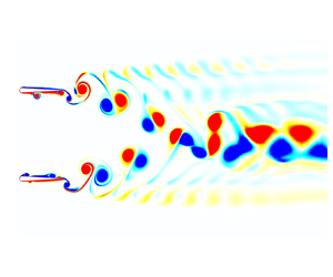
Figure 4. Contour of spanwise vorticity ( $\omega _{z}^{*}$) of parallel foils for (a) $St=0.25$ and $d^*=1$ (merged wake), (b) $St=0.3$ and $d^*=1.5$ (separated wake), (c) $St=0.5$ and $d^*=2$ (transitional-merged wake) and (d) $St=0.4$ and $d^*=1$ (separated wake) at different time instants for in-phase and out-of-phase pitching. Here, vorticity is normalized by $U_{\infty }/c$. (See supplementary movies 1, 2, 3 and 6, available at https://doi.org/10.1017/jfm.2022.785, for the entire wake evolution of (a–d), respectively.)

Figure 5. Classification of the wake patterns of foils in a side-by-side configuration for  $Re=4000$ at (a) a range of separation distances and Strouhal numbers for in-phase pitching, (b) a range of phase differences and Strouhal numbers for $d^*=1$. Dashed lines correspond to the boundary that distinguishes merged and separated wakes.
Table 2. Streamwise location ( $x/c$) and time instant ( $t/P$) in which the wake merging occurs as well as the percent improvement in the cycle-averaged coefficient of thrust ( $\Delta \widetilde {C_T}$) for separated and transitional-merged wake cases at $St=0.4$ and $St=0.5$.

Hereafter, we present quantification of important characteristics of the wakes and propose a model that distinguishes emerging vortex patterns. At this point, it is important to recall the dipole model by Godoy-Diana et al. (Reference Godoy-Diana, Marais, Aider and Wesfreid2009), which presented a quantitative threshold for the wake deflection behind a single oscillating foil. This model also remains valid for the wake of undulating foils (Khalid et al. Reference Khalid, Wang, Dong and Liu2020). The wake of oscillating foils, consisting of a reverse BvK vortex street, is dominated by shedding of a counterclockwise (positive sign) and a clockwise (negative sign) vortex per oscillation cycle. These vortices are located slightly above and below the centreline, respectively (Koochesfahani Reference Koochesfahani1989). The structure formed by these two vortices is called a dipole. Circulations of the vortices in a dipole induce a velocity normal to the line that connects the vortex centres as described by the 2-D Bio-Savart rule (Naguib, Vitek & Koochesfahani Reference Naguib, Vitek and Koochesfahani2011). When the self-advection velocity of the dipole is strong enough, it diverts the dipole from the centreline, which is followed by the consecutive dipoles. Therefore, the model was based on the offset between advection velocity of the propulsive wake, i.e.  $U_{phase}$, and self-induced translation velocity of the dipole, i.e. $U_{dipole}$. They can be mathematically defined as
 \begin{gather} U_{phase}={\rm d}X_i/{\rm d}t, \end{gather}
 \begin{gather}U_{dipole}=\varGamma / 2 {\rm \pi}\xi, \end{gather}
where  $X_i$ is the $x$ coordinate of a vortex core, $\varGamma$ denotes the average of magnitudes of circulation of counter-rotating vortices and $\xi$ represents the distance between the centres of the vortices (see figure 6a). Circulation ( $\varGamma$) is computed either from a line integral of the velocity field or from a surface integral of vorticity over the area bounded by a closed curve. Godoy-Diana et al. (Reference Godoy-Diana, Marais, Aider and Wesfreid2009) used a rectangular frame, whose size was determined by a Gaussian fit, to extract the boundary of each vortex towards calculating $\varGamma$. However, this method has a downside of potential numerical errors due to the possibility that rectangular frames may include counter-rotating vortices, particularly in the case of structures traversing in close proximity of one another. Therefore, we use a non-predefined closed curve to accurately capture each vortex proposed earlier by Khalid et al. (Reference Khalid, Wang, Dong and Liu2020), which eliminates this error in computing $\varGamma$. The boundary of the curve is defined such that it only encompasses the region with a magnitude of vorticity ( $\omega$) greater than $10\,\%$ of its value in the flow field. Then, we determine the circulation of each vortex by calculating the line integral of the velocity field around the curve using the definition
 \begin{equation} \varGamma=\oint \boldsymbol{V}\ {\cdot}\ {\rm d}\boldsymbol{l}, \end{equation}
where  $\boldsymbol{V}$ is the velocity and ${\rm d}\boldsymbol{l}$ is the infinitesimal length. This method ensures that circulation is computed without any penetration by a neighbouring vortex with oppositely signed vorticity. Hence, regions in which circulations of positive and negative vortices are calculated are entirely separated from each other by non-predefined boundaries around these coherent flow structures.

Figure 6. (a) Demonstration of the parameters used in the proposed model. (b) Effective phase velocity of the coupled vortex system with respect to radial displacement of the dipoles.
For the effective phase velocity ( $U^*_{p}$), Godoy-Diana et al. (Reference Godoy-Diana, Marais, Aider and Wesfreid2009) defined it in the following manner that yields positive values for deflected wakes:
 \begin{equation} U^*_{p}=(U_{phase}-U_{\infty}) \cos\alpha - U_{dipole}. \end{equation}
Here  $\alpha$ is the angle between $U_{phase}$ and $U_{dipole}$ as presented in figure 6(a). We present here a model that distinguishes different classes of vortex patterns using $U^*_{p}$. Although the model of Godoy-Diana et al. (Reference Godoy-Diana, Marais, Aider and Wesfreid2009) successfully predicts whether the wake is deflected behind an isolated oscillating foil, it cannot identify the nature of the vortex patterns, i.e. merged or separated, for multiple parallel foils, forming complex wakes in close proximity of one another. In order to construct an effective mathematical model, our current work focuses on differentiating merged and separated wakes and supplying information about the direction of their deflections. To illustrate it further, in-phase pitching of a transitional-merged wake at $St=0.5$ and $d^*=2$ exhibits deflection during each stage of wake development. During the separated stage at $t_1=30P$, both top and bottom wakes are deflected downwards, whereas the wake fully transitions to that of a merged configuration at $t_2=90P$. In the latter stage, the upwards deflected bottom vortex street and downwards deflected top vortex street is observed (see figure 4c). However, the model proposed by Godoy-Diana et al. (Reference Godoy-Diana, Marais, Aider and Wesfreid2009) cannot distinguish the vortex patterns for these configurations since all the cases consist of deflected wakes. Similarly, a separated wake with deflected vortex streets at $St=0.4$ and $d^*=2$ (see figure 7a) and a separated wake with horizontal vortex streets at lower $St$ and $1.5 \leqslant d^* \leqslant ~2.5$ (e.g. figure 4b) are treated disparately by the model, although they are all classified as separated wakes. Thus, we introduce the term $\sin \alpha$ to the formulation to take the direction of deflection into account, because $\sin \alpha$ yields positive values for upwards wakes and negative values for downwards and non-deflected wakes. Moreover, a weight factor term, $W_i$, which yields $-1$ for diverging separated wakes and $1$ for the rest, is incorporated into the equation to distinguish the separated wakes of out-of-phase pitching parallel foils. Hence, the effective phase velocity of the coupled vortex system or $U^*_{p,sys}$ can now be defined as
 \begin{equation} U^*_{p,sys}=\frac{U^*_{p,upper} \sin{\alpha}_{upper}}{U^*_{p,lower} \sin{\alpha}_{lower}} \, W_i. \end{equation}
Here,  $W_i$ is the wake weighting function defined as
 \begin{equation} W_{i} = \begin{cases} 1, & \text{small $\beta$ ($|\beta| < \beta^*/\epsilon$)}\\ \sin(\beta)/|\sin(\beta)|, & \text{large $\beta$ ($|\beta| \geqslant \beta^*/\epsilon$)}, \end{cases} \end{equation}
where  $\beta =\alpha _{lower}-\alpha _{upper}$ and $\beta ^*=|\alpha _{lower}|+|\alpha _{upper}|$. Here, $\epsilon$ denotes a positive number, which helps setting up a threshold for different classes of wakes under a broad range of kinematic parameters. We examine the performance of this weight factor term with $\epsilon = 5$, $7.5$ and $10$, and all these values serve the purpose very well.

Figure 7. Contour of spanwise vorticity ( $\omega _{z}^{*}$) of in-phase pitching parallel foils at $d^*=2$ for (a) $St=0.4$ (separated wake) and (b) $St=0.5$ (transitional-merged wake) at different time instants. Here, vorticity is normalized by $U_{\infty }/c$. (See supplementary movies 3 and 4 for the entire wake evolution of (b,a), respectively.)
Equation (3.5) yields negative  $U^*_{p,sys}$ values for merging wakes, whereas separated wakes produce positive $U^*_{p,sys}$. The model requires $U^*_{p}$ and $\sin {\alpha }$ for the upper and lower vortex dipoles (see figure 7a) that are shed in the same pitching cycle. Although it can be calculated at a certain location, it is preferred to trace these dipoles as they move in the downstream direction. It helps demonstrate that the model is not limited to a specific location but is valid for the whole domain. Figure 6(b) shows variations in $U^*_{p,sys}$ for separated, merged and transitional-merged wakes with respect to the radial displacement given by $r=\sqrt {(X_1-X_0)^2+(Y_1-Y_0)^2}$, where $X_1$ and $Y_1$ define an instantaneous location of a vortex core. Moreover, $X_0$ and $Y_0$ provide the location of the vortex core just after its detachment process from the foils is completed. Note that a geometric mean of the respective quantities for the counter-rotating vortices is used as the location of the dipole. Because the counter-rotating vortices are shed alternatively from each foil, it is also important to mention that each dipole is formed by those two counter-rotating vortices that have a smaller distance between their centres. It is evident from the plot in figure 6(b) that the proposed model successfully differentiates between separated and merged wakes for the given parametric space.
In this model, separated and merged stages of transitional-merged wakes are treated individually and marked with different colours, since these stages are contradictory to one another in terms of their vortex configuration. It is important to note that merged wake cases are tracked for a relatively short radial displacement, i.e.  $r/c\leqslant 3$. This is because their upper and lower vortex streets merge at mid-wake, which inhibits further tracking. However, dipoles of the separated wakes are traceable until circulation of the vortices shrink to negligible values due to the viscous diffusion around $r/c=5$. To clarify the working mechanism of the model, $U^*_{p}$ of merged wakes (see figures 4(a) or 4(c) at $t_2=90$) yields positive values for both bottom and top vortex streets as they are deflected upwards and downwards, respectively. Furthermore, $\sin {\alpha }$ for top and bottom wakes switch signs ( $\sin {\alpha }<0$ for top and $\sin {\alpha }>0$ for bottom), which results in $U^*_{p,sys}<0$. On the other hand, horizontal vortex streets in the separated wakes (see figure 4b) have $U^*_{p}<0$ and $\sin {\alpha }<0$, thus leading to $U^*_{p,sys}>0$. The separated wake, whose vortex streets are deflected (see figure 7a), or a transitional-merged wake at the separated stage (see figure 4(c) at $t_1=30P$) yield $U^*_{p}>0$ and $\sin {\alpha }<0$, which translates to $U^*_{p,sys}>0$. Finally, diverging separated wakes whose vortex streets are deflected in opposite directions yield positive values for $U^*_{p}$ and opposite signs for $\sin {\alpha }$ ( $\sin {\alpha }>0$ for top and $\sin {\alpha }<0$ for bottom). However, it gets $-1$ from the weight factor since $\beta =\alpha _{lower}-\alpha _{top}<0$, which translates into $U^*_{p,sys}>0$.
The classification and mathematical modelling of the vortex patterns presented here is developed for  $Re=4000$. However, it relies on kinematic quantities of coherent structures in the wake, such as the angle between vortex cores, the circulation of vortices and the phase velocity of dipoles. Therefore, it is expected to work well for low and medium $Re$ ranges considering all the flow topologies, i.e. von Kármán street, reverse von Kármán street and deflected von Kármán street, observed for $10 \leqslant Re \leqslant 2000$ (Das et al. Reference Das, Shukla and Govardhan2016), already covered in the analysis. It is noteworthy to state that the coherent structures remain the same even though the wake transitions to 3-D at $Re=8000$ (Verma & Hemmati Reference Verma and Hemmati2021). A similar argument can be made for the range of oscillation amplitudes. Patterns of the coherent structures behind oscillating foils for a range of oscillation amplitudes (Godoy-Diana et al. Reference Godoy-Diana, Aider and Wesfreid2008; Das et al. Reference Das, Shukla and Govardhan2016) do not fundamentally differ from those considered in the current study. This suggests that wakes of oscillating foils at different oscillating amplitudes can be classified and mathematically modelled using the presently proposed procedure. In an effort to test this, we also simulate cases for $\theta _0=5^{\circ }, 11^{\circ }$ and $14^{\circ }$ at a range of $St$ for $d^*=1.5c$. Their wakes display characteristics of one of the three vortex patterns examined above: separated wake, merged wake or transitional-merged wake. Furthermore, (3.5) performs excellently in distinguishing different topologies of the wake. Nevertheless, these results are not shown here for brevity.
3.2. Mechanism of wake merging
After establishing a mathematical model to quantitatively identify and characterize different wake patterns behind pitching foils in a side-by-side (parallel) configuration, we focus our attention to identify and explain the mechanism of wake merging. To this effect, we analyse primary transitions in the wake of in-phase pitching foils by associating it with the production and dynamics of secondary vortex structures. When an oscillating single foil produces a deflected wake, secondary structures appear from the primary vortex street to move away from the direction of deflection (Gungor et al. Reference Gungor, Khalid and Hemmati2021). Such secondary structures were also observed in the experiments of Godoy-Diana et al. (Reference Godoy-Diana, Aider and Wesfreid2008) and Jones et al. (Reference Jones, Dohring and Platzer1998) and numerical simulations of Liang et al. (Reference Liang, Ou, Premasuthan, Jameson and Wang2011). But no further analyses were conducted for this important feature of the wake dynamics. These structures are considerably weaker in their relative strength compared with those in the main street, which is why they have not received adequate attention in the literature. We hypothesize that secondary structures play a key role in the merger of upper and lower vortex streets behind parallel oscillating foils. Figure 7(a) shows a separated wake of the foils for the case of  $St=0.4$ and $d^*=2$ at $t=60P$. Even though secondary structures are present in the wake, structures from the lower wake are convected in the downstream direction before reaching the upper wake. At $St=0.5$ and $d^*=2$, in which wakes are merged, however, these secondary structures from the lower foil deflect upward to interact with the primary street of the upper foil, traversing downward (see figure 7b). These observations hint that this interaction triggers the wake merging process, because constructive or destructive interference of secondary vortices with the bigger coherent structures change their strengths in terms of circulation (Zhu et al. Reference Zhu, Wolfgang, Yue and Triantafyllou2002; Akhtar et al. Reference Akhtar, Mittal, Lauder and Drucker2007; Khalid et al. Reference Khalid, Wang, Akhtar, Dong, Liu and Hemmati2021a,Reference Khalid, Wang, Akhtar, Dong, Liu and Hemmatib). Furthermore, onset of the complete wake merging appears located very close to the point of interaction between secondary structures and the primary street. For instance, secondary structures shed by the lower foil at $St=0.5$ and $d^*=2$ catch the upper main vortex street at $x/c \approx 4$, which coincides with the location for the merging of wakes (see figure 4c). Likewise, both the interactions between secondary structures and the upper wake as well as the merging of upper and lower wakes occur at $x/c \approx 3.6$ for $St=0.5$ and $d^*=2$ (see the supplementary movie 3 and table 2). The alignment of the spatial merging location and that of the vortex interactions strengthens our argument on the role of these smaller structures in initiating and facilitating the wake merging process.
We proceed with providing another quantitative explanation to the impact of secondary structures on the overall wake dynamics. In this manner, the locations and circulation of vortex dipoles are traced in the wake to provide evidence for the impact of secondary structures. Figure 8 exhibits the change of  $\varGamma$ for negative vortices associated with separated ( $St=0.4$ and $d^*=2$) and transitional-merged ( $St=0.5$ and $d^*=2$) wakes, as dipoles move downstream. For the transitional-merged wake (figure 8b), circulation of the negative vortices of the upper and lower wakes overlap in the near wake region. However, proximity in this sense is broken in favour of the upper wake, after which there is constructive interference of secondary structures with negative vorticity at $r/c \approx 3.5$. This observation remains valid at different time instants. Non-dimensional circulation at $t_1=44P$ and $t_2=55P$ is presented in figure 8(b). On the contrary, there exists no significant difference in circulation of the upper and lower wakes for the separated wake (figure 8a), because the secondary structures have no influence on the upper wake. Similarly, wakes at $t_1=40P$ and $t_2=50P$ show that this trend is independent of the wake evolution and time. It is apparent that enhancement of the negative vorticity of the upper wake due to the influence of the secondary structures causes alterations in deflection of the vortex street (see (3.2) and (3.4)). It eventually results in the primary wake transition, i.e. merger of the wakes. We also note that relatively weaker and smaller secondary structures compared with the primary vortices could be the reason for the gradual merging of the vortex streets in transitional-merged wakes. As illustrated in figures 8 and 9, they have a delicate but significant effect on the upper vortex street, which may result in the crawling merging process (see supplementary movie 3 for the entire process). Therefore, the dynamics of secondary structures only account for the merging mechanism and physical process, while the discussion in § 3.1 outlines the mathematical model to effectively categorize the wake patterns. Furthermore, circulation of negative vortices of the upper and lower wakes is computed for other separated wakes and transitional-merged wakes to support this explanation for this mechanism. It is evident from figure 9 that our illustration stays valid for all transitional-merged wake cases investigated in this study.

Figure 8. Magnitude of non-dimensional circulation of negative vorticity of upper and lower vortex streets at  $d^*=2$ for (a) $St=0.4$ (separated wake) and (b) $St=0.5$ (transitional-merged wake before the merger) at different time instants for in-phase pitching.

Figure 9. Magnitude of non-dimensional circulation of negative vorticity of upper and lower vortex streets for transitional-merged wakes before the merger and separated wakes for in-phase pitching.
3.3. Effect of wake merging on the propulsive performance of the system
We now focus on the relationship between propulsive performance of in-phase pitching parallel foils (side-by-side configuration) and primary transitions in the wake by assessing the cycle-averaged performance metrics. Figure 10 shows temporal variations of the coefficients of thrust and power, as well as efficiency at a range of  $St$ and $d^*$ for the system (average of foils 1 and 2) and an isolated foil. The performance parameters of this dynamical system are examined for a large number of oscillation cycles until all cases reach quasi-steady conditions in their propulsion performance. This translates into 40 cycles for isolated cases, 65 cycles for cases with $St=0.4$, 90 cycles for $d^*=1$ and $St=0.5$ and $d^*=1.5$ and $St=0.5$, and 120 cycles for $d^*=2$ and $St=0.5$ and $d^*=2.5$ and $St=0.5$. Figure 10 covers all transitional-merged wakes observed in the current study as well as separated wakes, i.e. $St=0.4$ and $d^*=2$, $St=0.4$ and $d^*=2.5$, $St=0.5$ and $d^*=2.5$, and isolated foils’ wakes. In this section we aim at establishing the impact of unsteady alterations in wake dynamics on the propulsive performance of the system. Thus, parameters for cases with lower $St$, i.e. $St \leqslant 0.3$, are not presented here as they display no significant wake transitions. Previously, it was demonstrated by Gungor & Hemmati (Reference Gungor and Hemmati2020) that parallel foils generated highly quasi-steady performance and wake characteristics for lower $St$ at $d^*=1$. With this background, it is further noted in the present study that the same attributions persist for other separation distances examined here. Power requirements of the system marginally vary in time, which translates into resembling trends for the cycle-averaged coefficient of thrust and efficiency. The percent improvement in thrust ( $\Delta \widetilde {C_T}$) is given in table 2 together with the location and time instant of the wake merging. Here $\Delta \widetilde {C_T}$ is calculated between the fifth cycle and the cycle in which the thrust coefficient reaches quasi-steady conditions, e.g. 90th cycle for $d^*=1$ and $St=0.5$, 120th cycle for $d^*=2$ and $St=0.5$. The first five cycles are disregarded, considering that the performance metrics of steady cases require five cycles to converge (Gungor & Hemmati Reference Gungor and Hemmati2020). It is evident from figure 10(a) that the generated thrust by transitional-merged wakes improves with time and reaches a steady state after the primary transition in the wake is established. This indicates that the wake merging process could be a contributing factor for thrust enhancement. Furthermore, it is important to note that the separated wakes presented here ( $St=0.4$ and $d^*=2$, $St=0.4$ and $d^*=2.5$, and $St=0.5$ and $d^*=2.5$) experience trivial alterations in propulsive performance parameters, which further supports our argument. Thus, we affirm that the merging of these wakes improves the propulsive thrust of the system by increasing thrust generation through amplification of the circulation associated with amalgamated vortices around the mid-wake. This results in the formation of a high-momentum jet on the centreline.

Figure 10. The variation of cycle-averaged (a) thrust and (b) power coefficients, as well as (c) efficiency of the system (averaged using foil 1 and foil 2), and the isolated foil in time at a range of  $St$ and $d^*$ for in-phase pitching.
There are two consequential inferences from figure 10 and table 2, which strengthens our argument. First, the time instance of peaks in thrust variation lags the instant of the wake merging process. For example, thrust generation for the case of  $St=0.5$ and $d^*=1$ has its maximum at $t/P=29$, whereas its wake merging occurs at $t/P=22$. Second, thrust enhancement in the system decreases as the streamwise location of the onset of wake merging moves downtream. This is due to the reduction in circulation of the dipoles as they travel downstream of the wake (see figures 8 and 9). When upper and lower vortex streets merge in closer proximity to the foils, amalgamated vortices have greater circulation. This causes an increased momentum jet that is induced by the vortex street. This is consistent with insignificant improvements in thrust for the case of $St=0.4$ and $d^*=1.5$, whose wake merging occurs farther in the wake, i.e. increased distance from the foils.
Propulsive performance metrics of isolated pitching foils are also presented in figure 10. These data are tracked for  $40$ oscillation cycles, negligible alterations are witnessed after $20$ oscillation cycles. Note that a single foil with $St=0.4$ and 0.5 forms deflected wakes with quasi-steady characteristics although it is not demonstrated here for brevity. This range of $St$ agrees well with the threshold $St$ for wake deflection shown in other studies (Jones et al. Reference Jones, Dohring and Platzer1998; Godoy-Diana et al. Reference Godoy-Diana, Aider and Wesfreid2008; Deng et al. Reference Deng, Sun and Shao2015, Reference Deng, Sun, Teng, Pan and Shao2016; Das et al. Reference Das, Shukla and Govardhan2016). Pitching foils in side-by-side configurations exhibit superior performance compared with a solitary foil. Although parallel foils with all separation distances produce less thrust compared with a foil in isolation, they require substantially less power. This results in improved efficiency for parallel foils. Similar findings are also presented by Huera-Huarte (Reference Huera-Huarte2018) and Dewey et al. (Reference Dewey, Quinn, Boschitsch and Smits2014). It is worth mentioning that efficiency of an isolated foil at $St=0.4$ does not substantially differ from the case with separated wakes ( $d^*=2$ and $d^*=2.5$). Likewise at $St=0.5$, an isolated foil attains similar efficiency with a transitionally merged wake ( $d^*=2$) when it is not merged ( $t/P \leqslant 78$) and a separated wake ( $d^*=2.5$). On the other hand, efficiency of the two parallel foils, in which the primary wake transition occurs, is greater than an isolated foil for the same $St$. These observations imply that interactions of wakes favourably impact the performance of these complex dynamical system.
We now proceed with implementing the finite-core vortex array model to our wake data, following Naguib et al. (Reference Naguib, Vitek and Koochesfahani2011). This model suggests that velocity profiles in the wake can be determined by superimposing a finite amount of vortex cores onto a uniform flow. Streamwise and transverse velocity profiles that are induced by superposition of  $N$ vortices can be determined using
 \begin{gather} \boldsymbol{u}(x,y)=U_{\infty}-\sum_{i=1}^{N}\frac{\varGamma_i (r_i)}{2{\rm \pi}}\frac{(y-y_{ci})}{r_i^2}, \end{gather}
 \begin{gather} \boldsymbol{v}(x,y)=\sum_{i=1}^{N}\frac{\varGamma_i (r_i)}{2{\rm \pi}}\frac{(x-x_{ci})}{r_i^2}, \end{gather}
where  $r_i$ is the radial distance from the $i$th vortex centre to the point of calculation, and $x_{ci}$ and $y_{ci}$ are the streamwise and transverse location of the centre of the $i$th vortex, respectively. The model requires that the number of vortices be greater than or equal to 10 in order to converge (Naguib et al. Reference Naguib, Vitek and Koochesfahani2011). To this end, locations and circulations of vortices within the range of $3 \leqslant x/c \leqslant 7$ are measured for $St=0.5$ and $d^*=1$ at $t_1=13P$ (separated stage) and at $t_2=50P$ (merged stage). The $St$ and $d^*$ of the flow are selected, considering it yields the highest percent improvement in thrust production (see figure 10 and table 2). Moreover, the range of execution is determined considering that the wake merging occurs following $x/c=2.5$ and that the circulation of the dipoles diminishes after $x/c \geqslant 7$. Mean streamwise velocity profiles calculated using the vortex array model are plotted for $x/c=4$ and $x/c=6$ in figure 11. High-momentum-surfeit regions are observed around the centreline ( $y/c=0$) for the merged wake ( $t_1=50P$), whereas two distinct peaks associated with the jets created by the upper and lower vortex streets are visible in the separated wake ( $t_1=13P$). The excessive momentum at the outlet profiles ( $x/c=4$ and $x/c=6$) created by the single velocity peak is greater than the combination of the two peaks. It clearly shows impact of the wake merging on the formation of high-momentum jets, which results in improving thrust production. Furthermore, we compare velocity profiles obtained from the vortex array model with contours of mean horizontal velocity from figure 12. The model accurately captures the general trend and locations of the velocity peaks. However, it underestimates the magnitude of the peaks in velocity profiles. This limitation may be due to the sampling space given we only consider the region after wake merging in our calculations for the model. This focus on a particular region is driven by our emphasis on the influence of wake merging. A finite-core vortex array model was also developed and utilized by Dewey et al. (Reference Dewey, Quinn, Boschitsch and Smits2014) to reproduce wake structures and time-averaged velocity fields around parallel foils for in-phase ( $\phi =0$), out-of-phase ( $\phi ={\rm \pi}$) and mid-phase ( $\phi ={\rm \pi} /2$) oscillations. Even though they successfully demonstrated merging of wakes for in-phase pitching foils, they were not able to observe transitional characteristics during evolution of the wake, because the Strouhal number of their study was limited to $St = 0.25$.

Figure 11. Cycle-averaged streamwise velocity ( $u$) profiles of in-phase pitching foils, normalized by $U_{\infty }$, obtained from the finite-core vortex array model for $St=0.5$ and $d^*=1$ at different time instants ( $t_1=13P$ and $t_2=50P$) and streamwise locations ( $x/c=4$ and $x/c=6$).

Figure 12. Cycle-averaged streamwise velocity ( $u$) contours normalized by $U_{\infty }$ of in-phase pitching parallel foils for $St=0.5$ and $d^*=1$ at (a) $t_1=13P$ and (b) $t_2=50P$.
The formation, growth and interaction of LEVs can be an important mechanism that impacts the propulsive performance of oscillating foils (Anderson et al. Reference Anderson, Streitlien, Barrett and Triantafyllou1998; Pan et al. Reference Pan, Dong, Zhu and Yue2012), while also impacting the wake development (Hemmati, Van Buren & Smits Reference Hemmati, Van Buren and Smits2019). To this effect, we now look at how alterations in the formation and growth of LEVs around the foils influence their propulsive performance during a separated-to-merged wake transition. The LEVs are formed when the angle of attack is high enough that a separation bubble is formed on the foils. Their presence and evolvement on the surface of a fin or wing is responsible for a large part of thrust and lift generation in aquatic locomotion (Borazjani & Daghooghi Reference Borazjani and Daghooghi2013; Bottom Ii et al. Reference Bottom Ii, Borazjani, Blevins and Lauder2016; Liu et al. Reference Liu, Ren, Dong, Akanyeti, Liao and Lauder2017; Xiong & Liu Reference Xiong and Liu2019) and insect flight (Ellington et al. Reference Ellington, Van Den Berg, Willmott and Thomas1996; Birch & Dickinson Reference Birch and Dickinson2001; Bomphrey et al. Reference Bomphrey, Lawson, Harding, Taylor and Thomas2005), respectively. Unsteady thrust variations of the foils in the transitional-merged wake ( $St=0.5$ and $d^*=1$) throughout the separated and merged time ranges is presented in figure 13, which clearly demonstrates that higher peaks and lower troughs are achieved after the wake merging. Contours of vorticity focusing on surfaces of the foils at time instants that correspond to the highest ( $\theta =8^{\circ }$) and the lowest ( $\theta =0^{\circ }$) angles of attack are shown in figure 14. This enables for the comparison of this process to the evolution of LEVs around the foils. Note that these instants roughly overlap with the times at which the foils yield their highest and lowest thrust generation, as marked in figure 13. Negative (clockwise rotating) and positive (counterclockwise rotating) LEVs are formed on the upper and lower surface of the foils at the separated stage of the wake evolution, respectively. On the other hand, constituting positive LEVs on the lower surface of foil 1 and negative LEVs on the upper surface of foil 2 is significantly suppressed when the wake is fully merged. Furthermore, it is evident from contour plots in figure 14 that stronger LEVs are formed after the wake merging, which hints at a potential factor for thrust enhancement. These observations are valid for the other transitional-merged wake cases with recognizable thrust enhancement as well, although they are not shown here for brevity. Note that profiles of unsteady thrust have two peaks and two troughs per oscillation cycle. The impact of LEVs on thrust generation can be explained through the low pressure region (suction) formed by vortices. The LEVs attached close to the anterior part of the foil favourably affect thrust by dropping the pressure in this region, whereas their influence is adverse if located around the posterior part of the foil. For example, foil 1 at $t_7=50.25P$ has an enhanced LEV around the front edge compared with foil 1 at $t_3=13.25P$. However, the distribution of LEVs on the rear surfaces of the foils are matching, which translates to thrust enhancements for foil 1. Likewise, the thrust of foil 2 at $t_5=49.75P$ is considerably larger than that of foil 1. This is due to stronger LEVs formed close to the forehead of foil 2, while a LEV with large negative vorticity is present on the rear part of the foil 1.

Figure 13. Variations in the unsteady thrust coefficient of foil 1 and foil 2 for  $St=0.5$ and $d^*=1$ (transitional-merged wake) for in-phase pitching. The separated stage ( $12 \leqslant t/P \leqslant 14$) of the wake evolution is illustrated in black and the merged stage ( $49 \leqslant t/P \leqslant 51$) of the wake evolution is illustrated in red.

Figure 14. Contour of spanwise vorticity ( $\omega _{z}^{*}$) around in-phase pitching parallel foils for $St=0.5$ and $d^*=1$ (transitional-merged wake) at various time instants during the separated stage: (a) $t_1=12.5P$, (b) $t_2=13P$, and merged stage: (c) $t_3=49.5P$, (d) $t_4=50P$. Here, vorticity is normalized by $U_{\infty }/c$. (See supplementary movie 5 for the entire wake evolution).
It was previously demonstrated by Gungor & Hemmati (Reference Gungor and Hemmati2020) that merging of vortex streets was accompanied by the restoration of wake symmetry for parallel foils. Both performance and wake characteristics exhibit symmetric behaviour with a delay of a half-pitching period. This lag between the foils is due to the formation process of vortex dipoles. Although TEV $_1$ and TEV $_2$ are shed at the same time (e.g. $t_5=49.75P$), TEV $_2$ establishes a dipole with TEV $_0$ that has been shed half a period prior to these TEVs, whereas the coupling of TEV $_1$ and TEV $_3$ are delayed by half a cycle. Therefore, the distribution of LEVs around foil 1 and foil 2 at $t_5=49.75$ in figure 14(e) is a mirror image symmetric with switched signs of vorticity with that around foil 2 and foil 1 at $t_7=50.25P$ in figure 14(g), respectively. Besides, shifting $C_T$ values for foil 1 by a half-period in either direction results in a perfect overlap with those for foil 2 during the merged stage of the wake evolution, or vice versa (see figure 13). Contrarily, there is neither a coherent similarity of the arrangement of LEVs around the foils between different time steps nor a half-period lag between performance parameters of foil 1 and foil 2 during the separated stage of wake evolution.
4. Conclusions
Numerical simulations on the flow around two pitching foils in a side-by-side configuration are examined at a range of Strouhal numbers,  $0.15< St<0.5$, phase differences, $0<\phi <{\rm \pi}$, pitching amplitudes, $5^\circ <\theta _0<14^\circ$, and, separation distances, $0.5< d^*<2.5$, at a Reynolds number of 4000. First, we classify the vortex patterns in the wake. In the Strohual number–separation distance phase map of in-phase pitching foils, separated and merged wakes, which exhibit quasi-steady performance and wake characteristics, are observed at lower Strouhal numbers. Small spacing between the foils yields the constitution of merged wakes, while separated wakes are seen at higher separation distances. On the other hand, transitional-merged wakes, which are often observed at high Strouhal numbers, exhibit wake evolution in time. Two distinct and deflected vortex streets shed by each foil are observed at early stages of the oscillations. Upper and lower vortex streets approach each other in time, which eventually results in merging of the wakes. A novel mathematical model is proposed, which quantitatively establishes the threshold for the two set vortex patterns. This model utilizes the locations and circulations of individual vortices in a dipole. It is further tested using the current parameter space and performs perfectly in determining if the wake is separated or merged.
Then, we proceed with evaluating and explaining the physical mechanism associated with the primary wake transition, observed in in-phase pitching foils. This analysis reveals a novel process in which secondary structures in the wake are responsible in part for the wake merging. The wake merging occurs when secondary structures from the lower vortex street are strong enough to form a constructive interaction with the main vortex street of the upper wake. This interaction triggers the merging of wakes by increasing the circulation of negative vortex in the upper vortex street. In turn, this impacts the resultant induced velocity (flow) by the two vortex streets, which now do not match, leading to further deflection of wakes and their subsequent merger. Finally, it is observed that merging of the wakes enhances propulsive performance of the foils by combining circulations of amalgamated vortices. This process induces a high-momentum jet around the centreline. Evolution of LEVs plays a major role in the performance enhancement. Alterations in the distribution of leading edge structures and the amplification in their strength, which occurs after the wake merging, is a contributing factor for the improvements in thrust generation.
Supplementary movies
Supplementary movies are available at https://doi.org/10.1017/jfm.2022.785.
Funding
This research has received support from the Natural Sciences & Engineering Research Council (NSERC). The computational analysis was completed using Compute Canada clusters.
Declaration of interests
The authors report no conflict of interests.


 Open access