


1 Introduction
Ultra-intense, ultrafast lasers[ Reference Danson, Haefner and Bromage 1 ] are widely used in strong field physics, such as laser wakefield acceleration[ Reference Tajima and Dawson 2 , Reference Wang, Li and Liu 3 ], high harmonic generation[ Reference Corkum 4 , Reference Ghimire and Reis 5 ] and terahertz radiation[ Reference Tokita, Sakabe, Nagashima, Hashida and Inoue 6 ]. These lasers are currently generated from a Ti:sapphire-based chirped pulse amplification (CPA) system[ Reference Strickland and Mourou 7 – Reference Mourou 9 ] or nonlinear crystal-based optical parametric chirped pulse amplification (OPCPA) system[ Reference Dubietis, Jonušauskas and Piskarskas 10 – Reference Zeng, Zhou and Zuo 12 ]. Due to the short storage time, Ti:sapphire is typically pumped by frequency-doubled Nd:YAG or Nd:glass solid-state lasers, which results in a bulky and complicated system with high cost. Compared with conventional CPA laser systems, the OPCPA system can obtain a shorter pulse duration and a higher peak power. Its pump laser needs a short pulse duration, a low time jitter, and smooth temporal and spatial distributions because of the intrinsic instantaneous process. Thus, the OPCPA system is more complicated and expensive.
Ytterbium (Yb)-doped solid-state lasers have attracted attention in the last two decades. The Yb-ion has a long storage time, which is suitable for adopting a diode laser as a pump. Ytterbium-doped lasers have been developed to exhibit high pulse energy and power[ Reference Hornung, Liebetrau and Seidel 13 – Reference Buenting, Sayinc, Wandt, Morgner and Kracht 26 ]. This kind of laser system can be used for table-top X-ray generation[ Reference Calendron, Meier and Hemmer 27 ].
The Petawatt Optical Laser Amplifier for Radiation Intensive Experiments (POLARIS) project based on the Yb:glass amplifier, which aimed to achieve a petawatt peak power output with a sub-hertz repetition rate, was started in 1999, and has demonstrated 54 J pulse energy[ Reference Hornung, Liebetrau and Seidel 13 – Reference Tamer, Keppler and Körner 15 ]. Meanwhile, the Petawatt Energy Efficient Laser for Optical Plasma Experiments (PENELOPE) project with designed parameters of 150 J/150 fs/1 PW/1 Hz based on the Yb:CaF2 crystal amplifier is under development[ Reference Albach, Loeser, Siebold and Schramm 16 ]. Based on the Yb:YAG crystal, 1 J pulses with a pulse duration of 5 ps at 0.5 kHz were realized using a cryogenic Yb:YAG active mirror amplifier[ Reference Reagan, Baumgarten and Jankowska 17 ]. Moreover, 200 mJ 1.1 ps 5 kHz pulses were obtained using thin-disk laser technology[ Reference Nubbemeyer, Kaumanns and Ueffing 18 ]. Using Yb:KYW, a pulse energy up to 27 mJ at 100 Hz was realized with a pulse duration of 560 fs[ Reference Papadopoulos, Pellegrina, Ramirez, Georges and Druon 19 ]. A pulse duration down to 182 fs was obtained with an output power of 8.7 W at 500 kHz[ Reference Kim, Yang and Lee 20 ]. Working at 1 kHz, 4.7 mJ pulses were obtained with a sub-picosecond pulse duration[ Reference Calendron, Çankaya and Kärtner 21 ]. Based on the Yb:KGW crystal, a 10 mJ-level pulse energy was achieved at 10 Hz[ Reference João, Wagner and Körner 22 ]. In addition, 21 μJ, 270 fs 60 kHz pulses were realized by a hybrid Yb:KGW regenerative amplifier[ Reference Yan, Liu and Chu 23 ].
Among the various Yb-doped crystals, Yb:KGW has a relatively high thermal conductivity, a broad bandwidth, a high emission cross-section and a large aperture (> 25 mm). Combined with additional nonlinear compression technology, we can further broaden the spectral bandwidth and obtain a shorter pulse duration. We propose a kilohertz ultra-intense, ultra-short Yb:KGW-based CPA system, called the Kilohertz Ultraintense ultrAshort Functional laser Unit (KUAFU). A mode-locked fiber oscillator works as a seed and is injected into a Yb:KGW-based regenerative amplifier after being stretched to a sub-nanosecond pulse duration (Figure 1). A multi-pass main amplifier will further boost the energy to above 40 mJ. We will apply cryogenically cooled Yb:KGW technology to restrain the thermal effect. Two stages of compression will be used after amplification. The first stage involves a common Treacy-type compressor, and could compress the pulse duration to below 300 fs with an efficiency of approximately 70%. The second stage involves a gas-filled multi-pass cell[ Reference Schulte, Sartorius, Weitenberg, Vernaleken and Russbueldt 28 , Reference Kaumanns, Pervak and Kormin 29 ] and would compress the pulse to approximately 25 fs with an efficiency of approximately 90%. As a result, a kilohertz terawatt (25 mJ/25 fs) laser beamline that is simple, compact, stable, with low cost, and with high wall-plug efficiency, can be obtained.
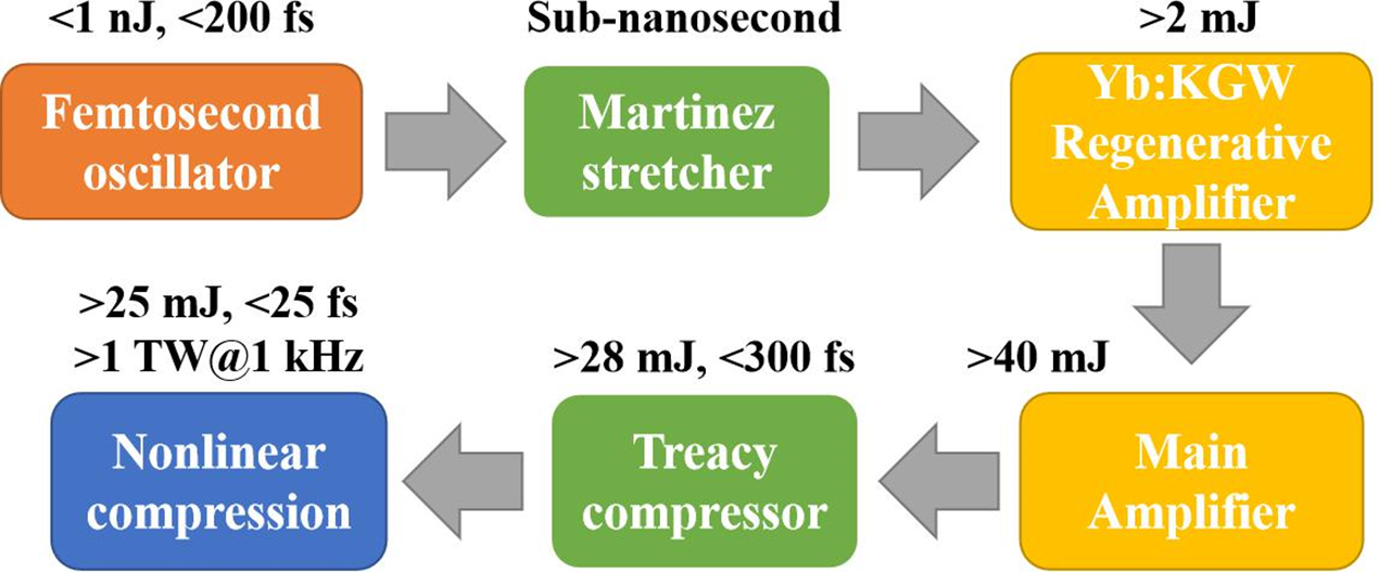
Figure 1 Conceptual design of the kilohertz ultra-intense ultra-short Yb:KGW-based CPA system.
We developed a diode-pumped Yb:KGW regenerative amplifier as the front end of the kilohertz terawatt laser system. Broad bandwidth pulses were obtained by applying dual crystals with different orientations of their optical axes[ Reference Calendron, Çankaya and Kärtner 21 , Reference Kim, Yang and Chizhov 30 ]. The cavity mode diameter was enlarged to 500 μm to achieve a high energy. The cavity parameters are specially designed to compensate the thermal lensing and preserve good beam quality. Finally, we experimentally obtained 1 kHz, 1.2 mJ pulses with a 9 nm bandwidth based on these considerations. A pulse duration of 227 fs was realized with preliminary compression. The laser fluence on the Yb:KGW crystal was no more than 0.8 J/cm2, which was far below the damage threshold. Once the cavity laser energy was over 1.5 mJ, however, the dichroic mirror was damaged because of low performance. We believe that we can further boost the pulse energy to over 2 mJ with new higher-quality dichroic mirrors and by further stretching the chirped pulse duration.
2 System design
Figure 2 illustrates the regenerative laser amplifier, which is composed of a fiber oscillator, a Martinez stretcher, a regenerative amplifier and a compressor. The fiber oscillator delivers 10 mW laser pulses with a repetition rate of 47.1 MHz and a spectral bandwidth of 15 nm. The regenerative amplifier was designed to amplify the seed pulses with a broadband output.

Figure 2 Laser system design. HW: half-wave plate; QW: quarter-wave plate; FR: Faraday rotator; TFP: thin-film polarizer; PC: Pockels cell; M1, M2, M6 and M7: cavity mirrors; M3 and M4: dichroic mirrors.
2.1 Gain-narrowing effect compensation
The Yb:KGW laser system has a quasi-three-level behavior. The net gain of the Yb:KGW crystal was not high: several tens of roundtrips were needed to amplify the nanojoule seed to a millijoule level. Thus, the gain-narrowing effect was inevitable in Yb:KGW regenerative amplifiers.
Several methods have been adopted to solve this problem. An acousto-optical programmable dispersive filter can be utilized to modulate the seed’s spectrum to suppress the gain-narrowing effect[ Reference Raybaut, Balembois, Druon and Georges 31 ], but it would add much more cost to this component. The intra-cavity spectral gain curve could be modulated by inserting an etalon that reduces the actual gain at the wavelength with the maximum gain factor[ Reference Yamakawa and Barty 32 , Reference Ogawa, Akahane and Aoyama 33 ]. Etalon insertion would lead to additional loss, however, time-to-time optimization would introduce the risk of component damage and instability to the system. A nonlinear regenerative amplifier could directly deliver pulses with a duration as low as 97 fs and a spectral bandwidth of 19 nm[ Reference Pouysegur, Delaigue and Zaouter 34 , Reference Neuhaus, Fink and Larionov 35 ], whereas the intra-cavity nonlinearity could result in system instability. One simple and robust method of solving this problem is by adopting a dual-crystal cavity design[ Reference Calendron, Çankaya and Kärtner 21 , Reference Kim, Yang and Chizhov 30 , Reference Kim, Yang and Chizhov 36 ]. This method was based on the fact that the spectral emission cross-section curves differ from each other when laser polarization is paralleled to the different optical axis of Yb-doped double tungstates[ Reference A.Lagatsky, Kuleshov and Mikhailov 37 – Reference Kim, Yang and Sall 40 ]. Thus, we adopted a dual-crystal design to compensate for the gain-narrowing effect.
In our system, two Yb:KGW crystals with different orientations were placed inside the cavity. Both crystals were Ng -cut crystals. One was placed with its Nm -axis parallel with the s-polarized direction. The other was placed with its Np -axis parallel with the s-polarized direction. A comparison was made between a configuration with the crystals placed in the same orientation (Np -axis parallel with the s-polarized direction) and that with crystals placed in the orthogonal orientation to reveal the design’s effect (Figure 3(a)).

Figure 3 (a) Illustration of gain-narrowing effect compensation under the dual-crystal configuration; (b) spectrum of Q-switched laser output under the two crystal placement configurations. The black line denotes the configuration with the crystals placed in the same orientation, while the red line is under the configuration of crystals placed in orthogonal orientation.
Figure 3(b) illustrates the output spectrum working at the Q-switched mode. The bandwidth in the orthogonal orientation was clearly much broader. The calculated Fourier transform limited pulse duration was as short as sub-160 fs. Under the configuration where the two crystals were placed in the same orientation, with the seed input, the amplified pulse bandwidth was only 3 nm with 180 μJ energy when it broke the dichroic mirrors. In contrast, the seed laser can be amplified to over 1 mJ under the orthogonal orientation configuration.
The combined gain is complex and should be measured under different pumping conditions because of the quasi-three-level system behavior of the Yb-doped gain medium. The blueshift, with one peak from 1037 nm under the same crystal placement orientation to 1035 nm under the orthogonal crystal placement orientation, could result from the reabsorption losses at a long wavelength in the crystal where the laser polarization is parallel to its Nm -axis, making the gain at 1035 nm higher than that at 1037 nm under orthogonal orientation.
2.2 Thermal lensing effect compensation
The thermal lensing effect can be estimated as[ Reference Clarkson 41 ]
 $$\begin{align*}{f}_{\mathrm{th}}(r)=\frac{2\mathrm{\pi} {K}_{\mathrm{c}}{r}^2}{P_{\mathrm{heat}}\left(\mathrm{d}n/\mathrm{d}T\right)s(r)},\end{align*}$$
where f th(r) is the focal length of the thermal lens; K c is the thermal conductivity of the laser medium; P heat is the part of the absorbed pump power that converts into heat; dn/dT denotes the thermal-optical coefficient; and s(r) is the fraction of the pump power contained in a beam radius of r.
Previous work showed that the dual-crystal configuration can be used to compensate for the thermal lensing effect[ Reference Eggleston 42 , Reference Calendron, Wentsch and Lederer 43 ], where the pulse energy can be boosted up to 6.5 mJ in a Yb:KYW regenerative amplifier working at 1 kHz[ Reference Calendron, Çankaya and Kärtner 21 ]. The dual-crystal configuration lowers the thermal load on each crystal while maintaining a high gain, and facilitates the compensation of each one’s thermal lensing effect. Therefore, the laser cavity can work with a large stability range over the thermal lensing effect variation.
Figure 4 shows the laser beam radius variation on the crystals versus the focal length of the thermal lens. The beam radius variation is below 13% when increasing the thermal lensing effect with a focal length ranging from 600 mm to 150 mm. The two pump lasers were both operated in the quasi-continuous wave (QCW) mode with 1/3 duty cycle at 1 kHz to reduce the thermal effect. The large stability range permitted a total pump input with peak power ranging from 30 W to 100 W. Thus, this configuration ensures good mode matching between the cavity mode and the pump laser.

Figure 4 Beam radius variation on the two crystals while changing the focal length of the thermal lensing effect.
In our experiment, we tested the cavity behavior under QCW pumping (1/3 duty cycle at 1 kHz) (Figure 5). The quarter-wave plate was optimized to obtain the maximum output power. A pump peak power up to 80 W was used, which corresponded to an average pump power of 26.6 W. A 3.14 W output power was reached with a slope efficiency of 20.9%. Meanwhile, owing to additional losses in the cavity, the output power was reduced to 2.25 W with a slope efficiency of 16.8% when the Pockels cell (PC) was inserted into the cavity.

Figure 5 Output characteristic of the cavity working under QCW pumping (1/3 duty cycle at 1 kHz) with a pump peak power up to 80 W. PC: Pockels cell.
2.3 Dispersion management
We used a transmission grating (TG) as a dispersive component in our stretcher and compressor. A compact configuration was adopted, where the stretcher and the compressor shared one grating similar to that in Ref. [Reference Kim, Yang and Lee20]. Figure 6 shows the ray-tracing model of the stretcher and the compressor.

Figure 6 Ray-tracing model of our stretcher and compressor. TG: transmission grating; P1, P2: periscope; M1: broadband high reflection mirror at 0°; M2–M6: broadband high reflection mirrors at 45°; L1, L2: lenses; S1: translation stage where M2 and M3 were fixed.
The Martinez stretcher stretched the seed pulses to ~250 ps with 1600 grooves/mm grating. The input of the stretcher (incident angle: 52°) and that of the compressor incident at the grating were from the same side; hence, a slight angular tuning of the grating could be made to obtain the best compression result. In the compressor, the input angle on the grating and the distance between the translation stage (S1) and the transmission grating (TG) were designed to compensate for the stretcher dispersion and all dispersion introduced by the materials. Figure 7 shows the calculated dispersion compensation result. The compressed pulse duration is around 185 fs when the duration of input pulses is 150 fs. The discrepancy between them will be significantly reduced with a longer pulse input because uncompensated high-order dispersion matters less for longer pulses. This configuration was used to show the compressibility of our amplified pulses at the preliminary phase of our whole system. In the future we would adopt a grating-pair compressor for fine compensation for high-order dispersion.

Figure 7 Calculated compressed pulse output (blue solid line) with 150 fs pulse input (dark dashed line) by our compact stretcher and compressor.
3 Results and discussion
The seed laser was amplified to 1.5 mJ after traveling 78 roundtrips in the regenerative cavity under a total of 70 W pump peak power (working at the QCW mode with 1/3 duty cycle at 1 kHz). As shown in Figure 8, the laser pulse underwent a unsaturated amplification because the high pulse energy induced damage to the dichroic mirrors. The sub-pulses between the cavity building-up modes are regarded as the pulse leakage of the pre-pulse before the main pulse seeds in, which could result from the low extinction ratio of our electro-optical cavity dumping system. Replacement of the PC for a better one or a fine adjustment of the PC orientation and the applied high voltage is needed to avoid this phenomenon. A fast pulse picker can be used to improve the nanosecond-scale contrast of the output main pulse.

Figure 8 Intra-cavity pulse amplification process monitored by an oscilloscope. The pulse underwent an unsaturated amplification because of the mirror damage limitation.
The two-pump laser could offer up to 120 W power. Approximately 60% of the maximum pump power was applied in our experiment considering the low performance of the dichroic mirrors. Under this dual-crystal configuration, our cavity supports a 100 W pump power input, as discussed in Section 2.2. High-quality dichroic mirrors will be used in the future, and laser pulses will be stretched to a longer pulse duration. Amplified pulses with an energy above 2.5 mJ can be expected by applying a higher pump power to the regenerative amplifier and making it work at the saturation level. The laser fluence of ~1 J/cm2 on the dichroic mirrors is believed to be below the damage threshold of high-quality dielectric-coated mirrors.
Figure 9(a) shows the output laser spectrum. The central wavelength lies at 1032 nm with a bandwidth of 9 nm. In comparison with that of the Q-switched output spectrum, the two peaks at 1030 nm and 1035 nm are located in the regenerative amplifier’s gain spectrum. The broadband seed with a central wavelength of 1038 nm facilitates gain-narrowing compensation. In the future, we will adopt a laser seed with a broader spectral bandwidth and apply an acousto-optical programmable dispersive filter to modulate the seed’s spectrum to make full use of the gain bandwidth of our regenerative amplifier.

Figure 9 (a) Input seed spectrum (black line) and output pulse spectrum (red line) delivered by the regenerative amplifier. (b) Compressed pulse duration (black line) and its Gaussian fit (red line) showing a pulse duration of approximately 227 fs. (c) M 2 factor of the output laser beam (inset: near-field and far-field beam profiles).
Due to the high transparency of our transmission grating, the laser pulses were compressed to 1.2 mJ with a beam diameter of 4 mm corresponding to a total compression efficiency of 80%. Thus, with a further improvement in our regenerative amplifier, 2 mJ compressed pulses can be expected, without damaging any component inside our compressor.
The compressed pulse duration was 227 fs (Figure 9(b)). The wings of the main peak are caused by the uncompensated high-order dispersion. In our system, the stretcher and the compressor share one same grating. Therefore there is little freedom for optimizing the dispersion compensation effect. Sub-200 fs pulses can be expected with a broader bandwidth seed input. Thanks to the dual-crystal configuration, the laser cavity delivers a near diffraction limited laser beam with M 2 around 1.1 (Figure 9(c)). The output laser would not suffer from beam deterioration when more pump power is applied.
4 Conclusions
This paper reports on the Yb:KGW dual-crystal cavity. The regenerative amplifier boosted the seed from sub-0.2 nJ to 1.5 mJ. The laser pulses were compressed to 1.2 mJ with a pulse duration of 227 fs. The output laser beam is near the diffraction limit with M 2 ~1.1, benefiting from the dual-crystal configuration. Moreover, the Q-switched output spectrum of the regenerative amplifier supports a sub-160 fs pulse amplification. Therefore, pulses with energies of up to 2 mJ and duration below 200 fs can be obtained using higher-quality dichroic mirrors and a broader-spectrum laser seed. This regenerative amplifier works as a good pre-amplifier for further laser amplification.
In the future, an investigation on the spectral gain curve of Yb:KGW in the main amplifier will be performed under cryogenic temperature evolution from 77 K to 300 K. The working temperature will be controlled to realize broader gain bandwidth and less shift at the central wavelength of the main amplifier. We plan to boost the pulse energy to above 40 mJ in two-stage multi-pass amplifiers, corresponding to a gain factor of 20. In each amplifier, we will also adopt two cascaded crystals placed under orthogonal orientation to reduce the thermal load on each crystal and compensate for the gain-narrowing effect.
Acknowledgement
This work was supported by the Natural Science Foundation of Top Talent of SZTU (Nos. 2019010801001 and 202024555101039).


 Open access