


1 Introduction
High-intensity ultrafast laser facilities provide laser pulses with ultra-high peak power within a few femtoseconds to picoseconds, which create unique and extreme laboratory conditions that can accelerate and collide intense beams of elementary particles[ Reference Malka, Faure, Gauduel, Lefebvre, Rousse and Phuoc1– Reference Seipt, Del Sorbo, Ridgers and Thomas3], actuate nuclear reactions[ Reference Kemp, Wilks, Hartouni and Grim4– Reference Ditmire, Zweiback, Yanovsky, Cowan, Hays and Wharton6], heat matter at conditions found in stars[ Reference Chen, Latham and Beraun7, Reference Patel, Mackinnon, Key, Cowan, Foord, Allen, Price, Ruhl, Springer and Stephens8] or even create matter out of the empty vacuum[ Reference Ataman9– Reference Bragin, Meuren, Keitel and Piazza11]. The progress of high-intensity ultrafast lasers promotes the development of a wide variety of fields, including high-field laser physics[ Reference Südmeyer, Marchese, Hashimoto, Baer, Gingras, Witzel and Keller12, Reference Kiriyama, Mori, Pirozhkov and Ogura13], laser ignition devices[ Reference Roth, Cowan, Key and Hatchett14, Reference Zang, Li, Zhang, Fu, Chen, Xu and Li15], the generation of hard X-rays[ Reference Yoshida, Fujimoto, Hironaka, Nakamura, Kondo, Ohtani and Tsunemi16, Reference Kmetec17], atomic physics[ Reference Salières, Carré, Le Déroff, Grasbon, Paulus, Walther, Kopold, Becker, Milosevic, Sanpera and Lewenstein18, Reference Ditmire, Springate, Tisch, Shao, Mason, Hay, Marangos and Hutchinson19], particle acceleration[ Reference Malka, Faure, Gauduel, Lefebvre, Rousse and Phuoc1, Reference Joshi, Mori, Katsouleas, Dawson, Kindel and Forslund20], attosecond science[ Reference Corkum and Krausz21, Reference Vincenti and Quéré22] and the generation of intense terahertz sources[ Reference Zeng, Zhou, Song, Lu, Li, Ding, Bai, Xu, Leng and Tian23– Reference Zhang, Ma, Ma, Wu, Ouyang, Kong, Hong, Wang, Yang and Chen25]. Thanks to the development of chirped pulse amplification (CPA) and optical parametric chirped pulse amplification (OPCPA) in recent decades, super-intense ultrashort lasers have been significantly promoted in many laboratories and have aroused the extensive interest of researchers[ Reference Strickland and Mourou26, Reference Piskarskas, Stabinis and Yankauskas27]. Nowadays, using CPA and OPCPA technologies, the peak power of super-intense ultrashort lasers has reached several petawatts (PWs) or even tens of PWs, and thus quite a few technologically powerful countries and laboratories are aiming at 100-PW lasers[ Reference Cartlidge28– Reference Li, Gan, Yu, Wang, Liu, Guo, Xu, Xu, Hang and Xu31].
However, a high-resolution time synchronization system that corrects the timing jitter of different time reference sources at each stage is extremely important to realize the value of these large scientific facilities. Schibli et al. [ Reference Schibli, Kim, Kuzucu, Gopinath, Tandon, Petrich, Kolodziejski, Fujimoto, Ippen and Kaertner32] first demonstrated a balanced optical cross-correlator (BOC) in 2003 to synchronize two mode-locked lasers with measurement accuracy of 300 attoseconds. The BOC method shows the advantages of a simple experimental setup, and the detected error signal is not affected by the amplitude noise of the lasers. Most importantly, the BOC method has excellent attosecond resolution measurement ability, so it is widely used in high-precision timing synchronization systems. Şafak et al. [ Reference Şafak, Xin, Zhang, Chia, Mücke and Kärtner33] introduced a method based on BOC to measure the local and remote timing jitter of two different mode-locked lasers, with root mean square (RMS) values of 2.1 and 8.55 fs, respectively. Casanova et al. [ Reference Casanova, Courjaud, Trophème and Santarelli34] reported a combined method to measure the absolute timing jitter of a mode-locked laser by combining two BOC systems with cross-spectrum technology.

Figure 1 Schematic illustration of the synchronization of the 100-PW laser and XFEL.
The project of the Shanghai X-ray Free Electron Laser (SHINE) was launched in 2018. In the project, a 100-PW laser will be built in the Station of Extreme Light (SEL) to create extreme conditions and new states of matter. In addition, the hard X-ray pulses from an X-ray free electron laser (XFEL) will be used to probe the ultrafast phenomena. As the pulse durations of the optical and X-ray pulses are 15 and 20 fs, respectively, precise synchronization of the two lasers with a synchronization accuracy of sub-20 fs is critical for pump–probe experiments. Therefore, the front end of 100-PW laser synchronization accuracy should be sub-5 fs due to the existence of systematic errors. In this work, we perform the synchronization of the front end of a 100-PW laser to a reference laser that will be synchronized to the timing master laser of the XFEL. The front end system contains a high-contrast optical parametric amplifier (seed) and a 200-TW optical parametric chirped pulse amplifier (preamplifier). By combining the timing jitter measurement with a feedback system, the RMS timing fluctuations of the seed and the preamplifier are controlled within 1.82 and 4.48 fs, respectively. This work lays the foundation for the precise synchronization of the 100-PW laser and XFEL, which will further provide the timing condition for pump–probe experiments.
2 Synchronization of the front end of the 100-PW laser
The synchronization scheme of the 100-PW laser and XFEL is shown in Figure 1. The 100-PW laser consists of a high-contrast laser seed, a 200-TW OPCPA preamplifier, an OPCPA main amplifier and a final optics assembly system. The pulses from the timing master laser of the XFEL are delivered to the control system as the reference signal (RS). The RS is first synchronized to an ultra-low noise commercial femtosecond laser (Menhir, Inc.) by a commercial BOC synchronization module (Cycle, Inc.), and then the oscillator of the high-contrast seed system is synchronized to the commercial femtosecond laser (Menhir, Inc.) also by the commercial BOC synchronization module. This method ensures accurate synchronization of the oscillator and RS, and the synchronization accuracy mainly depends on the BOC module. The subsequent amplifiers are synchronized to the seed by a home-built timing fluctuation measurement and feedback control system. So far, the synchronization of the seed and preamplifier is realized, which will be thoroughly discussed in the following sections.
2.1 Timing fluctuation measurement and correction between the regenerative amplifier and oscillator
For the ultra-intense laser, a seed with high contrast and broadband spectrum is one of the prerequisites. In previous work, a seed laser with 1012 temporal contrast and 200 nm bandwidth has been built[ Reference Shao, Li, Peng, Wang, Qian, Leng and Li35]. The seed laser is driven by a commercial Ti:sapphire laser (Astrella, Coherent, Inc.) with an average power of 7 W, a repetition rate of 1 kHz, a pulse duration of 35 fs and a center wavelength of 800 nm. The oscillator of the Ti:sapphire laser system can be synchronized to an RS from the XFEL. In addition, a part of its output power is injected into the regenerative amplifier and amplified after repeated reciprocation in the regenerative cavity. In this progress, the laser pulses propagate over hundreds of nanoseconds, which is equivalent to a tens of meters optical path. Considering the temperature fluctuation caused by the diode pump and environment, the regenerative amplifier might be a major source of the timing drift in the high-contrast seed system. Therefore, it is necessary to characterize and control the timing fluctuation of the regenerative amplifier.

Figure 2 (a) An overview of the synchronization for the seed and preamplifier. OPA, optic parametric amplification; HCF, hollow core fiber. (b) Timing measurement and feedback control links. MPC, multi-pass cavity; M1–M8, mirrors; CM1, CM2, chirped mirrors; DL, delay line; BOC, balanced optical cross-correlator. (c) Schematic of the noncollinear BOC. M, mirror; BS, beam splitter; GP, glass plate; BBO, beta barium borate crystal; BPD, balanced photodetector.
An overview of the synchronization for the seed and preamplifier is shown in Figure 2(a). In the setup, the timing systems of the oscillator and amplifiers are connected in series to prevent mutual interference. The laser pulses from the amplifier and oscillator are sent into a timing measurement and feedback control link, shown in Figure 2(b). The laser pulses from the oscillator with 2 nJ pulse energy and 72 MHz repetition rate pass through a stable multi-pass cavity (MPC) and chirped mirrors for the compensation of optical distance and dispersion. The MPC consists of two high-reflectivity concave mirrors with 250 mm focal length. The distance between the concave mirrors is set to 810 mm. After 25 round trips in the MPC, the pulses from the oscillator travel a similar distance to the ones from the amplifier, which ensures the measured pulses are from the same pulse in the oscillator and the timing jitter caused by the oscillator is eliminated. Two lenses with 1 m focal length are utilized to optimize the beam divergence of the input and output of the MPC, respectively. In order to ensure the stability of the MPC system, we built it on a separate platform with high thermal stability, good vibration isolation and damping characteristics, and made a box with the same material to isolate the MPC system from the surrounding space, ensuring that the input and output pulses characteristics of the MPC system are constant. The chirped mirrors are used to compensate the dispersion (~880 fs2) introduced by the transmission and reflection.
The amplifier pulses propagate 117 ns (35 m in distance) in the regenerative amplifier and pass through a delay line for timing control. The timing drift between the laser pulses from the oscillator and amplifier is measured by using a BOC, which has been widely used to characterize the timing fluctuation between different optical pulses due to its excellent attosecond timing resolution and robustness to environmental fluctuations[
Reference Schibli, Kim, Kuzucu, Gopinath, Tandon, Petrich, Kolodziejski, Fujimoto, Ippen and Kaertner32,
Reference Schulz, Schmuser, Zemella and Arsov36,
Reference Xin, Şafak and Kärtner37]. The structure of a noncollinear BOC is shown in Figure 2(c). The pulses from the oscillator and amplifier are combined and split by a 50:50 beam splitter (BS). Each half of the combined beam is focused on a 2-mm thick type-I $\left(\theta ={29.2}^{\circ },\varphi ={0}^{\circ}\right)$
beta barium borate (BBO) crystal for sum frequency generation (SFG). A 100-μm thick glass plate is inserted into one arm to introduce an additional optical path difference as the time offset reference for the cross-correlation signal.
$\left(\theta ={29.2}^{\circ },\varphi ={0}^{\circ}\right)$
beta barium borate (BBO) crystal for sum frequency generation (SFG). A 100-μm thick glass plate is inserted into one arm to introduce an additional optical path difference as the time offset reference for the cross-correlation signal.
The intensity of the sum frequency is measured by a balanced detector (PDB450, Thorlabs, Inc.) while generating a baseband voltage signal proportional to the time offset reference. The baseband voltage signal can characterize timing fluctuations and can be used to synchronize two light sources with different wavelengths. The delay line moves according to the baseband voltage signal to compensate for timing fluctuations. The noncollinear SFG configuration enables background-free detection by separating the cross-correlation signal from the fundamental and the second harmonic pulses. To avoid additional time jitter, the timing fluctuation characterization and correction system is built on a temperature-insensitive and vibration-isolated platform.
At the beginning, the oscillator pulses are directly delivered into the BOC without passing through the MPC and chirped mirrors. In this case, the measured oscillator pulses propagate many more times in the resonant cavity than the amplifier pulses. Meanwhile, as the timing reference from the XFEL has not yet been sent into the oscillator, the cavity has not been locked. Thus, the cavity length changes continuously because of the heat accumulation during the operation. Therefore, the timing fluctuation caused by vibration of the oscillator cavity is included in the measurement. From the BOC measurement, a timing-to-voltage conversion ‘S’ shape function is obtained. The slope of the linear region of the ‘S’ curve is 2.5 mV/fs, which represents the measurement accuracy of the BOC. Figure 3(a) shows the measurement result of the in-loop timing drift over 5 hours. Controlled by the time fluctuation measurement and feedback control system, the timing fluctuation between the oscillator and regenerative amplifier is compensated to 2.61 fs RMS. The feedback bandwidth is 5 Hz, limited by the speed of the stepper motor in the delay line. The movement trend of the feedback delay line is also recorded. As shown in Figure 3(b), the delay increases monotonically to about 700 fs over 5 hours, which means the same time increase without feedback. As the cavity of the oscillator is not locked, the timing fluctuation between the oscillator and amplifier is mainly caused by the cavity length drift. The environmental temperature fluctuation during the timing measurement is recorded around the amplifier. There is no obverse correlation between the trend of temperature variation shown in Figure 3(c) and the timing fluctuation shown in Figure 3(b).
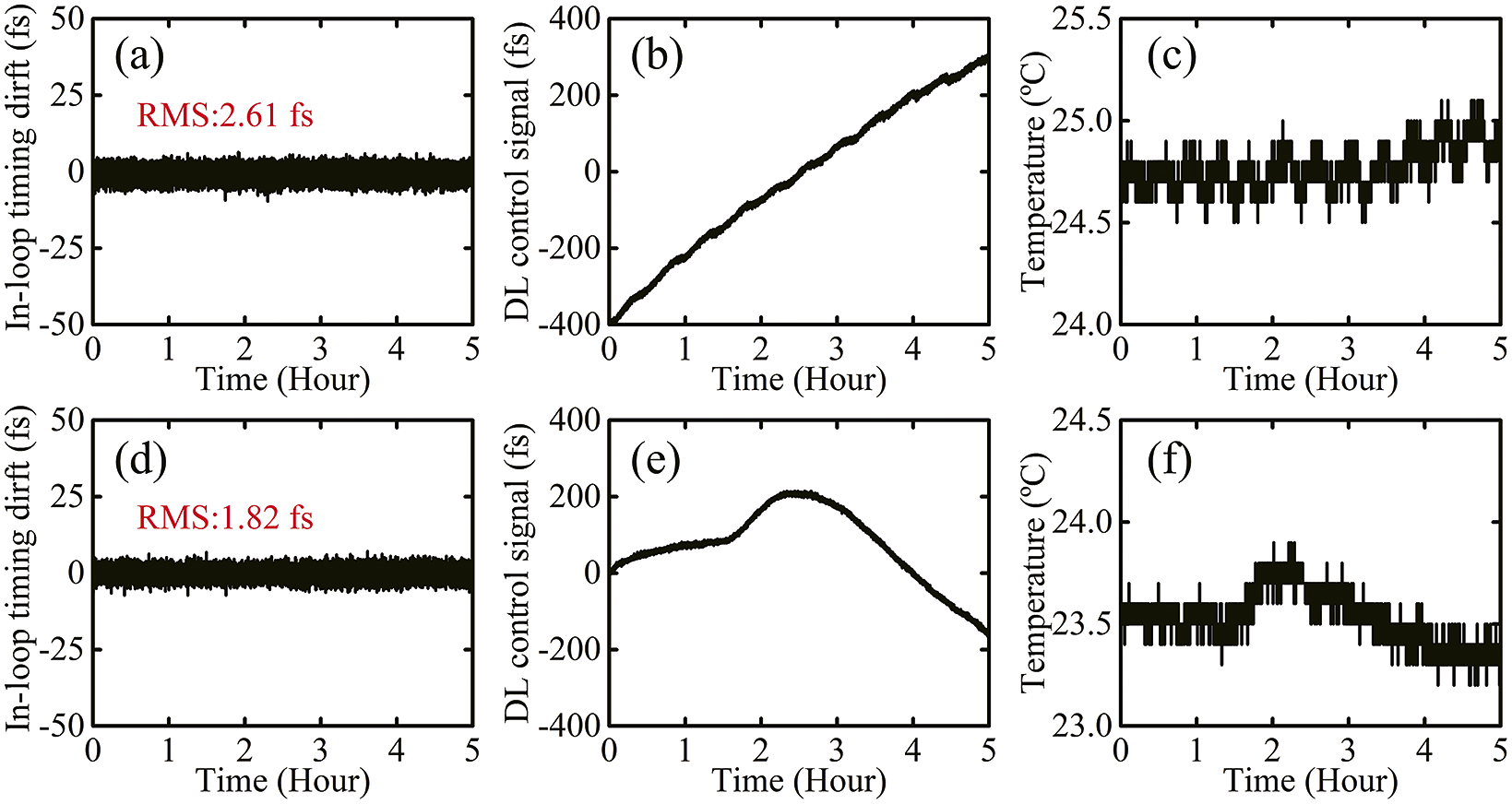
Figure 3 Regenerative amplifier timing drift measurement results without the MPC for more than 5 hours: (a) in-loop timing drift, (b) DL control signal and (c) environment temperature fluctuation. (d)–(f) The measurement results of the in-loop timing drift, DL control signal, and temperature variation over 5 hours with the MPC in the optical path, respectively.
To avoid the influence of the oscillator cavity, the optical path difference between the oscillator and amplifier is compensated, for example, the measured pulses are emitted at the same time from the oscillator cavity. The pulses travel about 117 ns in the regenerative amplifier, corresponding to 35.1 m in length. A stable MPC is used to increase the optical path of the oscillator pulses, ensuring that the pulses participating in the SFG process in the BOC are the same ones from the oscillator cavity. In this condition, the timing fluctuation is controlled to 1.82 fs RMS over 5 hours, shown in Figure 3(d). The changes of the delay line and environment temperature are shown in Figures 3(e) and 3(f), respectively. It is worth noting that the variation trend of the delay line is in good agreement with the temperature variation around the amplifier, which indicates that the timing fluctuation of the regenerative amplifier is caused by temperature variation. The fluctuation can be largely eliminated by a home-built timing synchronization system.
2.2 Timing fluctuation measurement and correction of the 200-TW preamplifier
As shown in Figure 2(a), an optic parametric amplifier is driven by the regenerative amplifier to generate a high-contrast infrared seed for the 100-PW laser. Afterwards, the OPA pulses are injected into a gas-filled hollow core fiber (HCF) and a thin BBO crystal for spectrum broadening and second harmonic generation. Through these processes, high-contrast broadband seed pulses around 910 nm are achieved[ Reference Shao, Li, Peng, Wang, Qian, Leng and Li35]. The seed pulses pass through a 200-TW preamplifier consisting of a double-grating Offner stretcher, three lithium triborate (LBO) crystal-based cascaded OPCPA amplifiers and a pulse compressor sequentially. The three-stage cascaded OPCPA amplifier contains three independent pump sources, namely OPCPA-1 (pulse duration is 4 ns, pulse energy is 100mJ at a repetition rate of 100 Hz), OPCPA-2 (pulse duration is 4.5 ns, pulse energy is 3 J at a repetition rate of 1 Hz) and OPCPA-3 (pulse duration 4.5 ns, pulse energy 25 J at a repetition rate of 0.1 Hz). Finally, a pulse train with pulse energy of 5.26 J, full spectral width of 210 nm at the center wavelength of 925 nm and pulse duration of 13.4 fs, close to the Fourier transform limit, is successfully output, and its peak power is as high as 263 TW[ Reference Wang, Liu, Lu, Chen, Long, Li, Chen, Chen, Bai and Li38].
Additional timing fluctuation is brought in during these stages. Because the repetition rate of the 200-TW preamplifier is 0.1 Hz, this is detrimental to the feedback control system, which requires a high repetition rate. Therefore, laser pulses from the first OPCPA stage with a repetition rate of 100 Hz are used in the experiment. The pulses pass through the following OPCPA stages without amplification but catch the timing information. This method not only ensures that the output pulses of the 200-TW preamplifier contain complete time drift information, but also obtains output pulses with a repetition rate of 100 Hz, which ensures that the feedback control system corrects the time fluctuation more accurately.
A timing link is built to compensate the timing fluctuation of the 200-TW laser pulses, as a timing measurement and feedback control link, shown in Figure 2(a). The experimental setup is similar to that of the preamplifier shown in Figure 2(b). In this setup, the pulses from the regenerative amplifier and the 200-TW preamplifier are injected into a noncollinear BOC through different optical paths. The distance between the two concave mirrors of the MPC is set to 800 mm, and the pulses perform 31 round trips in the MPC, which is equivalent to a 49.6 m optical path to compensate the optical path length caused by the 200-TW preamplifier. In the noncollinear BOC setup for the preamplifier, a 150-μm thick glass plate is used to increase the measurement range. The analysis and control system processes the BOC signal and controls the delay line to correct the timing jitter in real-time.

Figure 4 Timing drift measurement of the 200-TW preamplifier over 120 minutes. (a) In-loop timing drift, (b) DL control signal and (c) environment temperature fluctuation.
The ‘S’ shape BOC curve characterizing the measurement accuracy is first measured, with a fitted timing-to-amplitude conversion slope of 64.44 mV/fs. Figure 4 shows long-term measurement of the in-loop timing drift, DL control signal and environment temperature. As shown in Figure 4(a), by turning on the feedback system with a feedback bandwidth of 100 Hz, the timing fluctuation of the 200-TW preamplifier is corrected to an RMS of 4.48 fs over 120 minutes. According to Figure 4(b), the DL control signal is continuously increased to 1074 fs over 120 minutes, which is much longer than the pulse duration of the 200-TW preamplifier and regenerative amplifier. The results show that the timing drift of the 200-TW preamplifier is severe. Severe timing drift not only affects subsequent experiments but also limits the possibility of integrating the 200-TW preamplifier into a 100-PW laser facility. During the timing drift measurement, the environment temperature variation is recorded beside the 200-TW preamplifier, as shown in Figure 4(c). Comparing Figures 4(b) and 4(c), the change trend of the DL control signal has a strong correlation with the temperature change trend outside the 200-TW preamplifier. Therefore, temperature is the main factor causing timing drift in the long-term stable operation of the laser systems.
As the results above show, the timing fluctuation of the laser pulses becomes much more serious after a complex system. This is because the nonlinear processes in OPA, HCF and OPCPA will bring in timing fluctuation and increase the noise from the seed and environment. The measured pulse energy stabilities of the seed and preamplifier are 0.7% and 4.6% in the RMS, respectively. The standard deviations of the seed pulses and preamplifier pulses with pointing fluctuation in the horizontal direction are 9.99 and 9.45 $\unicode{x3bc} \mathrm{rad}$
, while those in the vertical direction are 8.67 and 10.77
$\unicode{x3bc} \mathrm{rad}$
, while those in the vertical direction are 8.67 and 10.77 $\unicode{x3bc} \mathrm{rad}$
, respectively. Large variations in pulse energy and beam pointing for the seed and 200-TW preamplifier greatly increase the difficulty of timing characterization and control. As these results show, to improve the synchronization accuracy, one efficient means is to improve the speed of data acquisition and the feedback bandwidth to eliminate high-frequency noise. However, the double arm configuration of the BOC can eliminate the fluctuation of the input pulse energy and spectrum to a certain extent because the energy and spectrum of the double arm increase and decrease simultaneously. However, the pointing fluctuation of the BOC input pulses leads to errors in the baseband voltage signal, which greatly affects the BOC measurement accuracy and increases the difficulty of synchronous work. Therefore, the measurement and control accuracies are limited in experiments. Recently, we have stably and flexibly delivered multi-μJ, sub-200-fs pulses in an approximately 10-m-long vacuum antiresonant HCF, which has been successfully used for high-power pulses synchronization and demonstrated its excellent immunity to environmental perturbations[
Reference Yan, Li, Huang, Wang, Liu, Liu, Pan, Luo, Yang, Zheng, Yin, Yu, Leng, Song, Pang and Jiang39].
$\unicode{x3bc} \mathrm{rad}$
, respectively. Large variations in pulse energy and beam pointing for the seed and 200-TW preamplifier greatly increase the difficulty of timing characterization and control. As these results show, to improve the synchronization accuracy, one efficient means is to improve the speed of data acquisition and the feedback bandwidth to eliminate high-frequency noise. However, the double arm configuration of the BOC can eliminate the fluctuation of the input pulse energy and spectrum to a certain extent because the energy and spectrum of the double arm increase and decrease simultaneously. However, the pointing fluctuation of the BOC input pulses leads to errors in the baseband voltage signal, which greatly affects the BOC measurement accuracy and increases the difficulty of synchronous work. Therefore, the measurement and control accuracies are limited in experiments. Recently, we have stably and flexibly delivered multi-μJ, sub-200-fs pulses in an approximately 10-m-long vacuum antiresonant HCF, which has been successfully used for high-power pulses synchronization and demonstrated its excellent immunity to environmental perturbations[
Reference Yan, Li, Huang, Wang, Liu, Liu, Pan, Luo, Yang, Zheng, Yin, Yu, Leng, Song, Pang and Jiang39].
To the best of our knowledge, we have achieved, for the first time, the long-term correction of timing jitter for a 200-TW laser pulse. The timing synchronization system will be applied to the main amplifier and the final optics assembly to synchronize the 100-PW laser facility pulses with XFEL pulses. Given the advantages of antiresonant HCF with a high damage threshold, low dispersion and low delay in data transmission, we have used it to transmit femtosecond laser pulses with high power and obtained preliminary results. The antiresonant HCF can not only improve the pointing jitter of the output pulses, but it can also eliminate the influence of the external environment on the RS, which greatly reduces the system error and will be integrated into the high-precision timing synchronization system for improved synchronization accuracy.
3 Conclusion
To summarize, we propose a high-precision timing synchronization system for long-term correction of timing jitter in the front end of a 100-PW laser facility. An MPC and chirped mirrors are used to compensate the optical path and the dispersion to improve the control accuracy. The timing jitter error signal was obtained by a BOC, and processed and corrected by a home-built analysis and control system. It is demonstrated that the high-contrast seed system of the 100-PW laser is synchronized to the oscillator with a fluctuation of 1.82 fs RMS for over 5 hours, and the 200-TW preamplifier is synchronized to the seed with a fluctuation of 4.48 fs RMS for over 120 minutes, which demonstrates the excellent performance of the synchronization feedback system. To the best of our knowledge, we have achieved, for the first time, timing characterization and control for a 200-TW laser. In the future, the timing synchronization system will be upgraded to control the timing of the main amplifier and the final optics assembly of a 100-PW laser facility. The timing system will provide the basic condition for joint pump–probe experiments of the 100-PW laser and XFEL.
Acknowledgements
This work was supported by the Shanghai High Repetition Rate XFEL and Extreme Light Facility (SHINE) project, the National Natural Science Foundation of China (62105346), the CAS Project for Young Scientists in Basic Research (YSBR-059), the 100 Talents Program of CAS and the Basic Research Project of the Shanghai Science and Technology Innovation Action Plan (20JC1416000). L. S. thanks Mr. Anan Dai and Prof. Bo Liu for valuable discussions.


 Open access