


1 Introduction: Apollon design and status
The Apollon laser, currently under construction at Orme des Merisiers, Saclay, France, will be among the first multi-PW installations in the world devoted to the study of high-intensity laser matter interaction in unprecedented regimes and with peak intensities surpassing  $2\times 10^{22}~\text{W}~\text{cm}^{-2}$. The final goal of the Apollon laser is the generation of 10 PW pulses corresponding to energy of 150 J and pulse duration of 15 fs at a repetition rate of $1~\text{shot}~\text{min}^{-1}$.
The general design characteristics of this unique laser facility have been already extensively presented in previous works[Reference Papadopoulos, Le Blanc, Chériaux, Georges, Mennerat, Zou, Mathieu and Audebert1–Reference Chériaux, Giambruno, Fréneaux, Leconte, Ramirez, Georges, Druon, Papadopoulos, Pellegrina, Le Blanc, Doyen, Legat, Boudenne, Mennerat, Audebert, Mourou, Mathieu and Chambaret3]. Here, we briefly remind the key features of the Apollon laser schematically represented in Figure 1. Apollon is based on a so-called ‘hybrid’ configuration where the optical parametric chirped pulse amplification (OPCPA) technology is optimally combined with Ti:sapphire-based high energy amplification. OPCPA is used in the Front End of the system to guarantee a large spectral bandwidth and high contrast injection pulses to an energy level of about 30 mJ. Main amplification takes place in five successive Ti:sapphire multipass amplifiers, all operating in the saturation regime, providing in total a gain of  $\times 10^{4}$. The final amplifier employs a state-of-the-art Ti:sapphire crystal of 175 mm diameter designed to provide more than 330 J. Pumping of the Ti:sapphire amplifiers is assured by a combination of different commercial laser sources (Thales and Amplitude Technologies) all operating at $1~\text{shot}~\text{min}^{-1}$, providing in total ${>}800~\text{J}$ in the 532–527 nm range. The wavefront of the amplified beam is then actively corrected by a deformable mirror based on the mechanical actuator technology providing high dynamic range $({>}100\unicode[STIX]{x1D706})$, high resolution (52 actuators) and high stability.
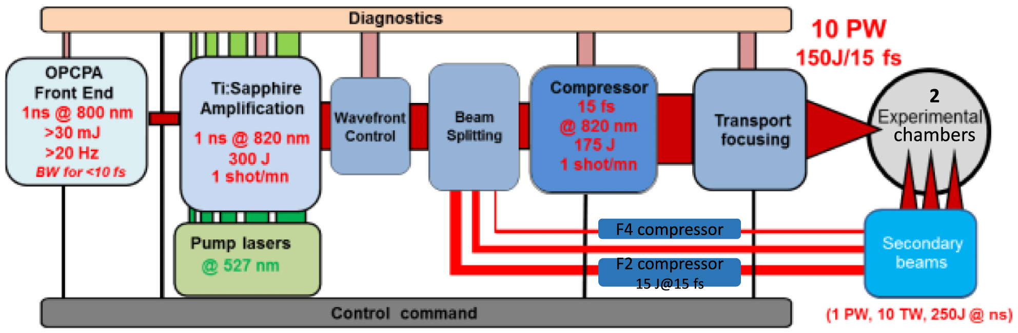
Figure 1. Global schematic of the Apollon 10 PW laser installation.
The beam is then separated into four beams: the main one (F1) to provide up to 150 J, 10 PW pulses after compression, the secondary 1 PW beam (F2) and two more beams: the remaining uncompressed (F3) beam (with variable energy depending on the energy required for F1) and a 10 TW level beam (F4) used as a probe beam. Compression of the F1, F2 and F4 beams is achieved in three separate gold grating-based compressors. Of particular interest is the main 10 PW compressor employing meter size gratings ( $910~\text{mm}\times 455~\text{mm}$) manufactured by Lawrence Livermore National Laboratory (LLNL) to safely manage the temporal compression with a beam size as large as $\unicode[STIX]{x1D6F7}400~\text{mm}$.
All four beams can be independently distributed in two separate, ionizing radiation protected experimental areas. The first one is dedicated for high-intensity laser matter interaction experiments using mostly solid targets and fast focusing parabolas ( $f=1~\text{m}$). The second one is mostly concentrated to electron acceleration experiments and gas targets using long focal distance focusing optics of several meters ( $f>8~\text{m}$).
The building of the Apollon facility has been delivered about one year ago ( $03/2015$). Since then, intense work to construct the laser has been carried out allowing us to set today an ambitious goal of the opening of the facility to the first users during 2018. Currently, most of the optical components ( ${>}90\%$) of the Apollon are either delivered or in the their final reception phase, including the critical ones such as the large gratings, the Ti:sapphire crystals and the $\unicode[STIX]{x1D6F7}400$ main beam transport mirrors to the experimental halls. Regarding the operation of the system, the Front End already operates close to its final operation point, scheduled to be commissioned before the fall of 2016. The amplification section is completed up to the 3.3 J level, while amplification to the 35 J level is scheduled for next July ( $07/2016$). Further amplification will be possible when the pump source is installed in our facility, currently in the final reception phase. For the compression of both F1 and F2 beams all optical components are in place, leaving only final optomechanical rectifications and vacuum tests to be completed before compression can be safely realized.
2 Temporal aspects of the Apollon laser
Several have been the challenges for the design and realization of the Apollon laser. Among them, maybe the most critical ones are those related to the temporal quality of the delivered pulses. Here, we discuss two aspects: the pulse duration and the pulse contrast. Indeed, we are trying to achieve the shortest pulses ever obtained for PW class systems. The typical design goal for the pulse duration for most of the Ti:sapphire-based PW class systems is around 25–30 fs, often limited in reality around 40–50 fs. In our case, very special care has been given to provide all the conditions to achieve, in a realistic and reliable way, 15 fs pulses. Our main motivation is of course the maximization of the intensity, considering the energy limitations due to the current fabrication capacity of large size Ti:sapphire crystals and gratings. The second very critical parameter is the quality of these pulses, often summarized by the so-called contrast ratio (CR). The CR definition is given in different temporal zones of the pulse, where specific upper limiting values of the ratio between the main peak of the pulse and its background are intended. In Table 1 we describe the intended parameters for the Apollon laser either in the few ps range (coherent range) or further away from the main peak in the ns range (incoherent range). These CR criteria are related to the laser matter interaction experiments scheduled for the Apollon facility, especially with solid targets, where any uncontrolled plasma preformation is generally unwanted.
The pulse duration and, even more, the CR are subject to numerous constrains, with the Apollon specifications considered among the most challenging and hard to achieve. An exhaustive list of these limiting factors is practically impossible, and in Table 1 we only mention those which we consider as the most important and which we have been investigating since the very beginning of the project.
Table 1. Temporal duration and contrast intended values and limiting factors considered for the Apollon laser design.

Most of the limiting factors listed above are directly related to the fundamental design considerations of our laser and their nature is more technological than physical. In other words, it is not a physical law that sets a definite upper limit, but, in a general manner, it is the currently available and commercially accessible technology of components and sources that governs the impact of this class of factors. On the contrary, however, a series of effects, which we group under the title of spatiotemporal coupling, presents a particular interest and a qualitatively different challenge. In these cases the limitation is inherent to a physical process resulting in the coupling of the beam parameters in space and time in a way that is often impossible to fully control. The interest in this case is to correctly quantify the impact, understand the nature of the process and ideally limit it to the minimum possible level.
In the following paragraphs we describe first the basic design considerations of our system and eventually how these considerations can guarantee the required performances against the first category of limiting factors. In Section 4 specific spatiotemporal effects are discussed both on the level of MIRO simulations[Reference Morice4], and first few experimental observations.
3 Design considerations of the Apollon laser: impact on the temporal aspects
The most critical point of our design is the Front End of the Apollon laser. Most of the qualities of the output pulses are defined at this stage, while for the rest of the system our design approach is conservative in the sense that, we try to assure that these initial qualities are preserved throughout the entire laser chain.
The Front End of Apollon combines two powerful technologies to provide large bandwidth, high-contrast pulses to the input of the main amplification section. Crossed polarized wave (XPW) generation and OPCPA, operating in the few picosecond regime, guarantee the generation of sub-10 fs pulses with a contrast estimated to be as high as  $10^{14}$[Reference Papadopoulos, Ramirez, Pellegrina, Lebas, Leblanc, Chériaux, Zou, Mennerat, Monot, Mathieu, Audebert, Georges and Druon5]. In Figure 2 a simplified schematic of the pulse characteristics evolution through the different stages of the Front End is shown. More details on the Apollon OPCPA and in particular on the OPCPA-pump challenges are given in Refs. [Reference Ramirez, Papadopoulos, Pellegrina, Georges, Druon, Monot, Ricci, Jullien, Chen, Rousseau and Lopez-Martens6–Reference Friebel, Pellegrina, Papadopoulos, Camy, Doualan, Moncorgé, Georges and Druon13].

Figure 2. Simplified diagram of the pulse characteristics evolution in the Front End of the Apollon laser.
To quantify these characteristics the output of the OPCPA stage of the Front End has been compressed using the Apollon stretcher, near the zero dispersion range, as a compressor for the few picosecond (6 ps) output pulses. In Figure 3 a Wizzler measurement of the compressed pulses is shown (upper part) as well as a high dynamic range third-order autocorrelation trace (lower part). We observe that the pulses can indeed be compressed in the intended range (below 10 fs) with a high amplified spontaneous emission (ASE) contrast limited by the dynamic range of the third-order autocorrelator  $({\sim}10^{12})$ and its spectral acceptance ( ${\sim}50~\text{fs}$).

Figure 3. Wizzler measurement (red line) and FTL pulse (black line) of the compressed ps-OPCPA stage of the Front End (upper graph). Third order autocorrelation of the ps-OPCPA pulses (lower graph). The device used for this measurement is a homemade Sequoia type 3rd order autocorrelator with  $750~\unicode[STIX]{x03BC}\text{J}$ input pulses.
The second design consideration concerns the main amplification section. This sub-system is designed to provide a low ASE noise, bandwidth preserving operation. The goal is to minimize the total ASE contribution below the  $10^{-12}$ level and to maintain a sufficient bandwidth of the amplified pulses to support their compression to the sub-15 fs duration. The ASE minimization is achieved by the combination of 5 amplification stages of low single-pass small signal gain ( ${<}5$). Recently the ASE from the two first Ti:sapphire amplifiers (3 J level) has been measured to be lower than $10^{-13}$. This represents a very promising first result since these two stages provide the highest gain in the chain and therefore are expected to contribute most of the ASE noise. On the other hand, bandwidth preservation is achieved by an optimized distributed spectral filtering strategy to compensate both the gain narrowing and the saturation induced red-shifting. Specially designed mirror coatings, based on an in-house developed optimization code, provide the required filtering function applied in only two points in the system minimizing the total energy losses[Reference Giambruno, Radier, Rey and Chériaux14].
The third critical design consideration is related to the beam transport throughout the complete laser chain up the experimental chambers. Two main aspects have been considered: (1) the imaging strategy and the minimization of chromatic aberrations and (2) the mirrors technology choice.
Relay imaging in the Apollon laser is based on an optimized combination of doublet lense-based telescopes (for beam diameter up to 18 mm), followed by 5 telescopes using  $90^{\circ }$ off-axis parabolic mirrors. The beam diameter is progressively increased up to 400 mm, while an input object plane (carefully chosen in the Front End section) is successively imaged in the middle of the 10 PW compressor. In Figure 4 a schematic of the imaging strategy of Apollon laser is presented. Zemax calculations of the residual optical path difference (OPD) at the extremities of the beam and the full spectral range (720–920 nm) indicate a total time distortion estimated less than 0.1 fs.

Figure 4. Schematic representation of the telescopes configuration in the Apollon chain (upper part). Zemax calculated total OPD for the final 400 mm beam over the full spectral range (720–920 nm) (lower part).
Mirror technology plays a crucial role for the temporal aspects of the Apollon laser. A set of highly challenging aspects is required including the high damage threshold, the low group delay dispersion (GDD), the large bandwidth and the large size. This combination restricts greatly the commercially available options which even until recently could not fully meet our requirements. Today a qualified, extensively tested and already partially delivered solution has been provided for the Apollon laser (Reosc SAFRAN) meeting all the critical requirements[Reference Hervy, Gallais, Cheriaux, Slimane, Freneaux, Bonod, Cotel, Clady and Sentis15]. Two alternative high laser induced damage threshold (LIDT) mirror coatings designs are in our possession.
The simulation of their reflectivity impact on the Apollon pulses is summarized in Figure 5 both in the spectral (upper graph) and the temporal domain (lower graph). For this simulation we simply consider the measured reflectivity of each mirror and perform a Fourier transform to the temporal domain neglecting any other contribution. The first design (D1) presents an LIDT in the range of  $3{-}5~\text{J}~\text{cm}^{-2}$ (for stretched pulses in the 1 ns regime) and very large bandwidth, comfortably supporting the transport of 15 fs pulses with insignificant impact on their contrast (red-line curves). The second design (D2) is a very resistive one with an $\text{LIDT}\;>10~\text{J}~\text{cm}^{-2}$ but with some restrictions on the reflectivity bandwidth (blue line curves). The impact of 4 of these mirrors on the Apollon pulse duration is estimated to be around 1 fs, while the contrast is still under the specifications (gray zone below the dashed line). The potential use of these mirrors is restricted for only 4 critical positions in our system (where the fluence is expected to be in the range of ${\sim}2~\text{J}~\text{cm}^{-2}$) and will be decided only in the case of an experimentally verified risk for the safety of the laser.

Figure 5. Spectral (upper graphs) and temporal (lower graphs) impact of the two alternative high LIDT mirror coatings designs (red and blue line curves) used in the Apollon laser.

Figure 6. Estimated compressed pulse form without any active spectral phase control (blue line curve) in the case of 15 fs Gaussian input pulses (green line curve).
The final key design consideration is related to the management of the spectral phase. Our approach is based on a two-stage minimization of the residual spectral phase. Initially, this is obtained with the precise optimization of the unmatched stretcher–compressor pair. Taking into account the exact type and quantity of material in the chain as well as the GDD of all the mirror coatings, we estimate that we can achieve a minimum pulse duration around 22 fs (assuming an ideal 15 fs Gaussian input pulse, shown in Figure 6). At a second level, this minimized residual phase will be actively compensated with the use of a high resolution and high dynamic range loop employing a Wizzler to measure it and a Dazzler to control it. We estimate that the residual phase to compensate is dominated by the fourth order (FOD) with a value around  $10^{5}~\text{fs}^{4}$ and therefore well in the capacity range of our Dazzler. However, the most challenging point is related to the optimization of the contrast in the sup-ps range. Here, we try to achieve CR values in the range of $10^{5}{-}10^{7}$, while the dynamic range of the Dazzler–Wizzler pair is already limited around $10^{5}{-}10^{6}$[Reference Grabielle, Moulet, Forget, Crozatier, Coudreau, Herzog, Oksenhendler, Cornaggia and Gobert16]. Therefore, we recognize that this optimization is among the most challenging for the Apollon system and its success is directly related to the implementation of accurate diagnostics and rigorous measuring procedures.
4 The impact of the spatiotemporal coupling
Four main spatiotemporal coupling effects have been identified and studied so far in the frame of the Apollon laser: (1) the inhomogeneous amplification in the Ti:sapphire disks due to spatial variations of the gain and the saturation, (2) the impact of the finite gratings size and the diffraction effects inside the 10 PW compressor, (3) the low-order spatial-to-spectral phase coupling in the compressors induced by the flatness imperfections of optics handling spectrally dispersed beams and (4) the high-order spatial-to-spectral phase coupling in the stretcher and the compressors induced by the rugosity of their optics.
4.1 Inhomogeneous amplification
The first effect refers to any kind of input beam spatial variations leading to a spatially varying total accumulated gain and saturation for each sub-section of the output beam. As a first example we studied the effect of a Gaussian input beam profile and its progressive evolution to a super-Gaussian one.

Figure 7. MIRO simulation of the spectrum of the amplified output beam of the Apollon laser as a function of the position in the beam.
In Figure 7, we show the MIRO simulation of the output beam spectral distribution across the beam. In this simulation we assumed a typical experimental input spectrum from the Front End, while for the spectral filtering in the amplification section we considered the existing filters, calculated to optimize the spectral evolution of the central part of the beam. Input and output energies are 10 mJ and 330 J, respectively.
We observe indeed that the broadest spectrum is obtained in the center of the output beam, where the gain narrowing and the red-shifting effect are nominally compensated. However, as we progressively reach the outer parts of the beam the corresponding input fluence is reduced leading to higher gain and less saturation. The result is less red-shifted and narrower spectra as we move from the center to the edge of the output beam. For this specific simulation, taking into account the energy content of each ring of the beam, we estimate that the corresponding average FTL duration is about 16 fs. However, this is only an approximation since the important parameter is the delivered intensity in the far-field of such an inhomogeneous beam. This study is ongoing along with dedicated experiments to further investigate the real impact of the effect. In parallel, an alternative optimization of the spectral filtering is scheduled to better balance the effect and provide a more uniform output beam.
The second impact of this radial dependence of the gain and the saturation dynamics is on the spectral phase due to the inhomogeneous atomic phase shift in the Ti:sapphire amplifiers. In a previous study[Reference Mennerat, Giambruno, Freneaux, Leconte and Cheriaux17] the effect has been already quantified to be on the order of 0.5 rad over the whole beam and the full spectral range and therefore is considered as insignificant (0.1–0.2 fs) compared to the spectral variation impact.
4.2 Finite size compressor gratings
The second effect is related to the limited size gratings used in high-intensity compressors. In the Apollon laser, for the 10 PW main compressor the size of the gratings ( $910~\text{mm}\times 455~\text{mm}$) is chosen to optimize the spectral transmission of the compressor and of course to eliminate the energy losses. However, there is a significant impact on the contrast of the output pulses due to the diffraction at the edge of the second and the third grating of the compressor (where the beam is spectrally dispersed). In fact, in our MIRO simulation we observe two contributions in the far-field of the compressed beam. Apart from the main one, a second highly dispersed structure sweeps across the focus both in space and time, generating a complex space–time coupled pedestal of about $10^{-5}$ in contrast, $\pm 300~\text{fs}$ around the main peak. In Figure 8 we present the integrated (in time) distribution of the beam in the far-field calculated by MIRO. With the red line, in the center of the graph, we represent the main intensity peak, while at earlier or later times we observe a fast moving pedestal going through the focus.

Figure 8. MIRO simulation of the impact in the far-field of the finite size gratings of the 10 PW compressor of the Apollon laser.
The complex character of the effect deserves further investigation and experimental verification to correctly define its real impact before corrective measures are decided. It is however highly challenging to experimentally investigate such an effect since it involves a spatial resolved measurement of the contrast in the coherent range. We are currently developing a test bench configuration where very high quality input pulses will be used as reference to study the relative contribution of the grating size effect in the near, the intermediate and the far-field of the beam.
4.3 Low-order spatial-to-spectral phase coupling
This effect is known since the early steps of CPA systems and it refers to the impact of the quality of the optics inside a stretcher or a compressor at positions where the spectrum is spatially dispersed. By ‘low order’ we refer to low-frequency wavefront aberrations and not the rugosity issues, discussed in the following paragraph. Two problems have been investigated in the frame of the Apollon project: (1) the optimization of the positioning of the 4 gratings for the 10 PW compressor and (2) the correct specification of the optical quality of the retroreflector in the folded 2-grating-based 1 PW compressor.
In the first case, we used MIRO in a parametric study based on the wavefront measurements of all the delivered gratings (data provided by LLNL). The goal was to decide the optimal position of each grating so that the pulse spatiotemporal degradation at the output is minimized. As expected, we found that the highest quality gratings should be placed in the second and third positions where the spatial-to-spectral phase coupling is most critical. Excellent PtV transmitted wavefront errors (TWEs) of  $\unicode[STIX]{x1D706}/6$ and $\unicode[STIX]{x1D706}/8$, respectively from these two gratings, restrict the pulse degradation effect around 15.3 fs with a total spatiotemporal Strehl ratio estimated around 95%. Neglecting the effect could lead to a severe pulses degradation resulting in 19–20 fs effective duration and a considerable intensity loss.
In the second study, our approach has been qualitatively different, since now we used our MIRO simulation to specify the required quality of a critical component such as the retroreflector of the 1 PW compressor. We found that in order to restrict the impact below the 15.2 fs we should specify a TWE of this element lower than  $\unicode[STIX]{x1D706}/4$ (PtV). This is far from trivial given the double mirror configuration of the retroreflector and the gravity effects on their flatness (the retroreflector folds the compressor in the vertical direction). In Figure 9 we present the measured TWE of the finally delivered optic, restricted below $\unicode[STIX]{x1D706}/8$ over the full surface ( $400~\text{mm}\times 177~\text{mm}$). Such an excellent retroreflector has almost no impact on the pulse duration, with MIRO estimating the duration in the range of 15–15.1 fs and the total spatiotemporal Strehl ratio ${>}99\%$.

Figure 9. TWE of the retroreflector of the 1 PW compressor (maximum  $\text{scale}=\unicode[STIX]{x1D706}/8$).
4.4 High-order spatial-to-spectral phase coupling
The qualitative difference of this last effect to the previously described is that now we refer to the rugosity issues of the same optics. The rugosity, as a fast variation in space, couples a fast variation of the spectral phase which in return scatters energy of the pulse in the time domain, before and after the main peak. Therefore, this mechanism is expected to principally affect the contrast rather than the pulse duration. Again, the effect is not new. In a relatively recent study from the OMEGA EP laser group from Rochester[Reference Bromage, Dorrer and Jungquist18] it is exhaustively analyzed and even a simple analytical model is provided to allow accurate predictions on the CR. In the Apollon context we used this model to explain the experimentally observed CR degradation of the Front End output pulses in the 1–30 ps range (Figure 3). The model seems to agree very well to the measured data revealing the strong impact of the convex mirror inside the Offner stretcher. Currently, we are preparing an experimental campaign to verify these preliminary findings based on the precise rugosity characterization of the optics under discussion, combined to a parametric study of the impact of different quality level components to the measured CR.
5 Conclusions
The Apollon 10 PW laser is moving fast to its final construction phase. Currently, we are working on the final alignment and optimization of the third amplification stage and the demonstration of the Apollon laser operation on the 35 J level. Regarding the rest of the system, almost all the critical components of the laser are either already delivered (transport mirrors, amplifier crystals, gratings, etc.) or in the final reception phase (high energy pump sources, deformable mirrors, special beam splitting optics, diagnostics, etc.). Commissioning of a first fully operating version of the Apollon laser on the multi-PW level ( ${>}75~\text{J}$ after compression / ${>}5$ PW pulses on the target) and opening of the facility to the international users’ community is scheduled for 2018. The final upgrade to the nominal 10 PW level will follow right after the first experimental campaigns on the multi-PW level.
In this work we provide a summary of the main considerations of the Apollon laser regarding one of the most critical characteristics of this system, the pulse temporal quality. The very challenging and strict requirements of the Apollon laser are justified and the key design and technological aspects of the system which guarantee their achievement are presented. A more detailed discussion is also included on the impact of the spatiotemporal coupling effects on both the duration and CR of the compressed pulses reaching the experimental target. To the best of our knowledge it is the first time that the impact of a series of effects such as the inhomogeneous amplification, the finite size gratings in PW class compressors, as well as the wavefront and rugosity limitations of critical optical components is discussed in the frame of a large-scale laser facility and the 15 fs second pulse duration regime.
Acknowledgement
The authors gratefully acknowledge financial support from the ILE-APOLLON 07-CPER 017-01 contract.


 Open access